Autopilot on AT91SAM7
1. Introduction
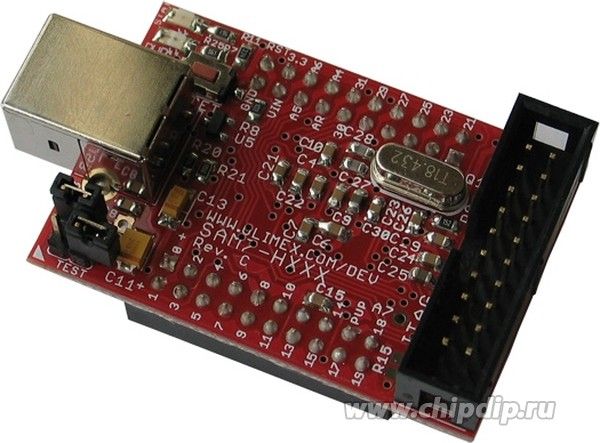
Radio-controlled airplanes I became interested in back in 2002, living in Prague. The first aircraft was with a wingspan of 1.2 m, engine 2-stroke engine. Here is a fragment of the video of those times. Once in 2008, the ADXL202E accelerometer fell into my hands. Having experience in developing devices on the controller of the MCS-51 family (this was the Rubidium frequency standard and data acquisition system), I decided to make an autopilot for the radio-controlled model Mentor. First of all, I connected the accelerometer to the controller. For simplicity, I chose a debug board with an AT91SAM7 controller, for the convenience and ease of working with it. It should be noted that I decided not to learn anything about autopilots on the Internet, but to do everything on my own with a “0” to make it more interesting.
So, by chance in 2008, I happened to fly on an airplane and be able to use a laptop on board and my scarf with an accelerometer. Today, any owner
tablet or smartphone can do this experiment on their own, because
Accelerometers are available in almost all devices. It was here that I made for myself the first "discovery" that the accelerometer can be used to stabilize the pitch (since the plane cannot pick up speed too fast or slow down), but it is not suitable for stabilizing the roll. Since with proper rotation without sliding, lateral accelerations are compensated by the roll of the aircraft, and the accelerometer does not feel them. I remember the movie Yolki-2 , where the roll of the aircraft was tracked by a glass of water, which will cause bewilderment to a real pilot. Why then invent artificial horizon?
So, in these articles I will describe what happened to me from 2008 to 2017, when I was engaged in this project in my free time. In June 2012, the autopilot was actually tested 1 time. Then still without GPS. In 2017, several tests were performed with GPS. One of the successful, in slow motion mode, but with no time to find your position on the GPS can be seen here . Start is to turn off the remote. The takeoff is fully automatic, then an attempt to seize control, when it became clear that the plane was not flying there. It was found that GPS determined the coordinates of 1 km approximately from the present. Another successful flight on the route 10/17/2017 . Shooting unsuccessful, but visible takeoff and landing. Landing in the field due to low battery. However, beautiful. The entire flight is fully automatic. Development began with the elaboration of the autopilot software model using Borland C ++ Builder and the XPlane 6 flight simulator. As a result, the program code was adapted for the controller with almost no changes. Autopilot is focused on simple docking with standard radio control modules. PPM (Pulse Position Modulation) was selected as the most suitable. Not with all modern consoles even PPM can work today: it is required that the sequence of PPM pulses go sequentially and not start at the same time as in some modern consoles, such as FlySky FS-16. Although the control solution from such consoles is also present in the software, but for today it has not been tested and needs to be debugged. The system is tested on Robbie Futaba FC-16 and Art-Tech EFLY-100B consoles. One of the drawbacks is the need to output the PPM signal directly from the interior of the receiver to a decoder - a pulse distributor for steering gears.
2. Software and hardware model
The functional scheme of the autopilot is shown in Fig.1. The heart of the autopilot is the LEVEL1 unit. This module is a high-priority function and runs independently of other events every (15.625 ms tested version) 46.875 ms. His task is to keep the aircraft in the correct flight position
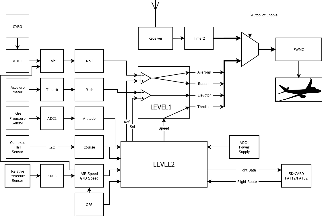
Fig. one
The input to the module is the FSSi structure, which contains the parameters Roll (Roll), Pitch (Pitch), and Air Speed (Air Speed). The correct position is considered when there are no signals Ref Ref = 0 and pitch = 0. This module also controls the controller of the aircraft’s engine and maintains the speed received from the LEVEL2 unit in accordance with the flight task. The Level2 module introduces a perturbation into the LEVEL1 module and thus forces it to retain not the zero roll and pitch values, but calculated in accordance with the flight task. The speed parameter is directly transmitted from the flight task. The output of the module is a data structure that contains the current position of the ailerons (ailerons), elevator (elevator), rudder or rudder (rudder) and throttle (throttle). This structure in the program is named FSSo. The module has the name FltStSys (flight stabilization system). It can be filed with the PWMC (Pulse Wide Modulation Controller) if autopilot mode is activated. Otherwise, the PWMC is supplied with a structure filled with a timer in accordance with the measured values received from the RF receiver. This control mode is traditional for radio-controlled models.
The Level2 module is slower, 1 time per second it forms control actions - it shifts zero points for the Level1 module. Data transmitted in Level1 is marked with the word keep in the program. Those. this is what the Level1 module should hold. This module performs all other functions:
1) the implementation of the take-off mode.
2) Hold height
3) Course retention
4) Calculation of the route and carrying the aircraft along the route specified on the SD card.
5) Record flight parameters to the SD card once per second. (Black box function)
6) When connected to one of the COM ports of the bluetooth module, the output of telemetry information.
The basic idea of building the autopilot LEVEL1 is to build a fully inertial aircraft piloting system that does not use external signals, such as photo sensors for sky and earth color temperature or, for example, NAVSTAR or GLONASS to keep the aircraft in normal flight position. When the GPS signal disappears, the flight is performed on a magnetic compass. The following sensors are used to meet these requirements:
- Roll. The value of the roll is calculated from the angular velocity of the turn of the aircraft and its linear velocity under the assumption that the turn occurs without sliding. The analog signal from the GYRO angular velocity sensor is digitized by the ADC controller (ADC1) embedded in the controller and then the Calc module calculates the roll.
- Pitch The pitch value of the pitch controller is obtained by measuring the pulse duration from the accelerometer sensor with a timer. This is permissible to do, because as a rule, the aircraft do not usually have too rapid changes in speed (except for take-off mode).
- Altitude. An absolute pressure sensor is used to measure altitude. Data is obtained in the form of voltage, which is digitized by one of the channels of the ADC (ADC2) controller.
- Course. To obtain the heading value, either the GPS module is used, or, if it is unavailable or at zero speed (before the start, the heading control), Honeywell's digital compass with Hall sensors. Connecting to the controller via I2C interface.
- Speed. Airspeed sensor on Pitot tube. A relative pressure sensor is used. The voltage from the sensor is measured by one of the ADC channels (ADC3) of the controller. Also for some things, the speed value from the GPS module is used.
- GPS GPS module is connected via com port. Used to obtain route data and speed relative to the ground (GND speed).
- SD card. It is not a sensor, but data on module settings (coefficients for formulas), route data are read from it. Flight data is recorded once per second.
3. Sensors and modules
3.1 Accelerometer
The sensor is designed to measure linear acceleration. The ADXL202E (Analog Devices) device is used as an accelerometer. This is a two-axis accelerometer with an output in the form of pulses, the duration of which is proportional to the acceleration. The pulse duration is measured by a timer. Only one of the axes (X) is used to measure the inclination of the aircraft. The Y axis can be used to calculate lateral acceleration and compensate it by trimming the rudder position. Now it is not implemented. This sensor shows the position of the "ball" in the corresponding sensor of angular velocity and slip of the aircraft (for example, I-18T, EUP-53 ). When turning (pilots turn is understood to mean any change in the aircraft's course), the pilot, in order to reduce the slip, usually steers the pedals and keeps the ball in a central position. The drift of the accelerometer when measuring the slope is shown in Fig. 2. As can be seen when placed in the refrigerator for 15 minutes, the drift was -5 degrees.

Figure 2
3.2 Gyro
The key element of the panel of any aircraft is the artificial horizon device. It is usually built on the basis of a mechanical gyroscope. It shows the roll and pitch of the aircraft in instrument flight mode. In this project, the MEV-50A semiconductor gyroscope is used to measure the aircraft roll. However, unlike the classical gyroscope, semiconductor gyroscopes do not measure the absolute roll, but its derivative — the angular velocity. This is the main reason why you cannot use a semiconductor gyro to measure aircraft roll. The drift of such a measurement system is not determined by anything at small angular velocities. If, for example, in a VR (virtual reality) helmet in which the gyroscope is not made on the basis of a magnetic compass with Hall sensors, but on a semiconductor device, you try to turn your head very slowly, you will find that it doesn’t notice the turning of the head. Therefore, I applied another way to calculate roll. The gyroscope is installed to measure the speed of the turn ω of the aircraft around a vertical axis. Then the aircraft roll can be calculated using the formula Θ = arctan (V ^ 2 / Rg) = arctan (Vω / g). See fig.3.
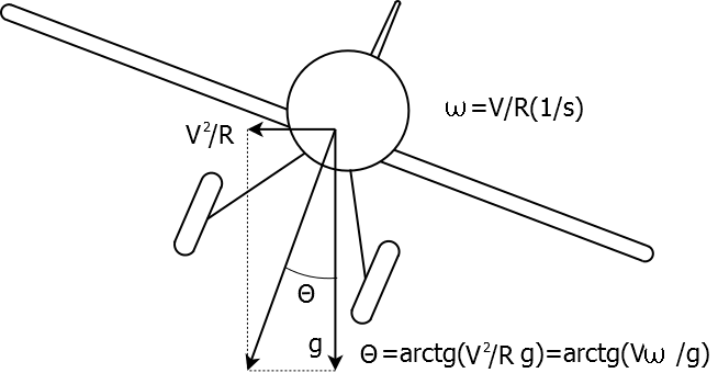
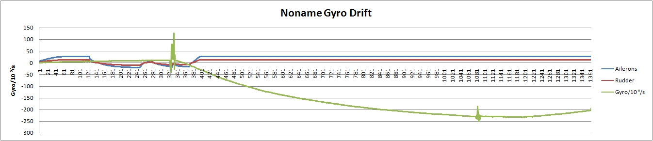
Here R is the turning radius of the aircraft, g is the acceleration of gravity (9.8 m / s2), V is the speed relative to the ground (true air speed), ω is the angular velocity, rad / s. The true speed is given by GPS, or it must be calculated based on the course, speed and direction of the wind. This project uses GPS speed. To exclude multiplication by 0, the minimum speed for the calculation is limited below 10 km / h. To the gyroscope installed in this way, there are very serious requirements for measurement accuracy. So, the first gyro that was tested led to the loss of the aircraft. A video of the flight can be viewed here , the data of the "black box" are also available. The plane would be raised from the console to a height of about 150m and the autopilot was turned on. However, as can be seen from the graphs, from the very beginning the gyroscope gave incorrect data - the Gyr in the picture - and, as soon as the autopilot was turned on for 97 seconds of flight, the plane entered the spin as expected. Unfortunately, it was not possible to bring it out safely due to ergonomic errors: manual control was turned on from the console with the middle position of the toggle switch, which could not be found in time from the excitement :). It was a gyroscope from a simple coaxial helicopter. In general, it was clear to me from the very beginning that this would be so, since the temperature tests in the refrigerator showed a huge drift of this device. Care in 15 minutes was about 15g / s, although the normal operating values of this parameter usually do not exceed several degrees per second in the entire range of rolls (up to 30 grams). And accuracy should be no worse than 0.1o / c.
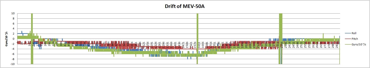
Look at the test data and the measurement process here. A comparison of the characteristics of gyroscopes is presented in Fig. 5. It can be seen that, in general, a normal flight could not be expected from a noname gyroscope if its drift was over 15 minutes. in the freezer was approximately 24 ° / s. Now used gyro MEV-50A . It is seen that its drift in 25 minutes is about 0.6 ° / s.
Pic.5
3.3 Altimeter
An absolute pressure sensor is usually used as an altimeter. The MPXA4115A6U sensor is used in this project. The sensor outputs a voltage that is measured by the controller. Before the flight it is necessary to warm up. Warming up time reaches 10-15 minutes. As the atmospheric pressure changes, the altimeter is automatically calibrated before each flight. The sensor has a significant temperature drift. Figure 6 shows the drift graph of the altimeter. Since the speed sensor is also a pressure gauge, the drift is the same.
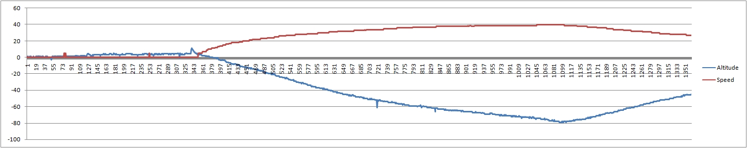
Fig. 6
The most interesting test of the pressure sensor is undoubtedly a trip to the subway. These black box trips are shown in Figure 7. About this schedule, we can say that the autopilot is turned on on the 12th floor, (about 36 m) Next, take the elevator, then I rode the bus, and then the subway. The end point of my journey, when I got off the subway, was really on high ground.

Fig.7
3.4 Airspeed sensor.
Air velocity is usually measured using a Pitot tube. In principle, these things are usually calculated. But it is clear that if you blow the outside into the tube (without touching it with your lips), then the pressure in it will increase. By measuring the pressure in the tube, you can estimate the speed of flight. The tube is usually placed either on the wing or on the fuselage (if there is no pulling screw). For correct measurement, it is necessary that the engine does not force air directly into the tube. Being a pioneer in this matter, I used the MPXV5004GP relative pressure sensor . As with the absolute pressure sensor, the output of this sensor is voltage; it is measured by the controller. When launched, it is also calibrated. But a coarse adjustment with a resistor is not required if the height cannot be zeroed, unlike the absolute pressure sensor. The tube was taken from carbon fiber with a diameter of 3 mm. See fig. eight.

Fig.8
To calibrate the sensor, the handset was installed on the rearview mirror of the car, and a control run was made, the current speed was recorded on the recorder. If you combine audio and log you can calibrate the airspeed sensor. So I "discovered" for myself that the speed is proportional to the square root of pressure. V = k * √p In the following, the accuracy of the speed measurement was confirmed during test flights with GPS. Temperature drift of the airspeed sensor can be seen in Fig. 6. Just made a scientific discovery. During acceleration, the air is pumped out of the passenger compartment, the pressure drops, which corresponds to an increase in height? Is it so? Correlation with height cannot be accidental ...
3.5 Digital compass
The digital compass allows you to determine the direction of flight in the absence of a signal or a GPS receiver. Initially, the system was built as inertial. The flight program was not recorded in the form of GPS coordinates, but was given the direction, speed and time of flight to the next point. As a compass was used 2-axis compass HMC6352 . If then the developer was smarter, he would certainly use the 3-axis compass. But so far done. The compass has an I2C interface. This device can directly issue a course, or levels of magnetic field components. To increase accuracy, it is sometimes necessary, or when changing the external magnetic environment, to calibrate it. For calibration, it is necessary to hold the calibration button when turning on the power of the autopilot, after which the controller enters the calibration mode for 1 minute. Calibration mode is indicated by a special flashing of the operation mode indicator (J9, BLUE-LED, 4 times per second). At this time it is necessary to make several complete turns of the aircraft in the strictly horizontal position of the aircraft. In order to be able to use the sensor, magnetic materials cannot be used for the autopilot body. Unfortunately, the first experiments showed that the measurement accuracy is good only if the device is strictly horizontal. On the plane, this requirement can not be fulfilled. Moreover, the accuracy does not just fall, but it does not exist at all. When tilted even at a small angle, a few degrees we get at the output all + -180 °. Therefore, we had to refuse to receive the course directly from the compass, but to receive the values of the components of the magnetic field, and calculate the course using compensation as much as possible. In the absence of the third Z axis, we had to take the value of this component as a constant. The result of the compass with and without compensation is shown in Fig.9. HDGn - uncompensated compass, HDGc - compensated. As can be seen from the graphs, compensation significantly improves the quality of course measurements, but of course there is no talk about accuracy in tenths of a degree. Also, the work of the compass can be seen on the flight data without GPS 11.09.2012. Here the flight took place in Vokhonovo . It should be noted that in flights in 2009 . there was no compass compensation yet. As you can see in the figure, the start really takes place with a course close to 120 degrees, and ends in a forest with a course of about 300 degrees. As shown by late flights, the plane was rocking strongly (yes, yes! :)) due to poor attachment of the wing to the fuselage and a decrease in flight speed after the engine was turned off.

Fig. 9.
3.6 GPS module
A GPS module with an integrated antenna is used. This is a small veil, located outside the shielded autopilot box. (See Fig.8). Module documentation can be found in the GPS folder. Used module S3126 . The GPS module is connected to the controller through one of the UART. Communication with the module is standard protocol NMEA0183. On test 2017_09_02 before the launch of the aircraft, the GPS did not work correctly, and the plane very beautifully flew in the wrong direction. As it was possible to see from the data of the "black box" TRACK005.LOG GPS "thought" that it is a kilometer away from a given point. This can be viewed in flight data from 2017_09_02 . It should be noted that in this test I still could not control the distance to the next flight point while the console was turned on (i.e. the autopilot was turned off). Therefore, the distance of 134 M in the log file did not indicate that the seat of the aircraft was determined correctly. The distance to the next point was supposed to be about 100 m, the offset was about 0, and the course was 323. However, as you can see, real data appeared only at the time of take-off at 14:10:33. And the course turned out to be 150, a distance of 1012M, an offset of 121M (deviation from the axis along which the aircraft should fly in accordance with the task). After this test, a change was made to the program so that the route data was displayed in telemetry regardless of the mode. It became possible to see before launch whether GPS works correctly. This control is also reflected in the launch map . Autopilot receives the following parameters from the GPS module: time, date (used when recording the log file), readiness, number of visible satellites, coordinates longitude, latitude and speed in knots. GPS readiness is indicated by a green LED flashing when the information is recorded on the map, approximately 1 time per second. It is important to understand that the GPS module can not as accurately as the coordinates determine the height, so the height is not used. When you turn on the autopilot, immediately after warming up and calibrating the sensors, the controller calculates the route using the coordinates of the flight task. This route is not recorded on the map, but is displayed via BT telemetry. From these data, we can estimate the correctness of the flight data. The program is not waiting for the initialization of GPS, but it is easy to change. Here is the telemetry log output:
GPILOT V2.17.0 24 / Jul / 2017
Waiting GPS ...
GPS ready ...
Init from MMC card..Hidden sectors = 57
G0,60.674983,29.173461,0,0,0,0,1
G1,60,675504,29.172667,30M, 50kM / h, 323D, 5s, 2.72M
G2,60.676388,29.171305,30M, 50kM / h, 322D, 8s, 3,123M
G3,60,675641,29.168697,30M, 50kM / h, 239D, 11s, 4,164M
G4,60,672877,29.172249,30M, 50kM / h, 147D, 26s, 5,362M
G5,60.673546,29.174448,30M, 50kM / h, 58D, 10s, 6.140M
G6,60,674767,29.173783,20M, 30kM / h, 345D, 16s, 7.140M
G7,60,675737,29.172313,20M, 0kM / h, 323D, 0s, 0.134M
Compass calibrate skip ...
Sensors calibrate ...
Sensors calibrate complete ...
3.7 Bluetooth Module
For the convenience of monitoring parameters before takeoff and debugging in general, the output through the UART was equipped with a bluetooth Parani-ESD1000 module . To communicate with other devices, a button is installed. The most convenient application for Android devices turned out to be the Bluetooth Graphics application. Available in Google Play.
3.8 SD card
Like any self-respecting plane, my project has a black box on board, played by an SD card. The card is connected via a slow SPI interface, for connecting it, I took the ready code from Rolf Freitag, for which I am grateful. The code provides reading and writing blocks of 512 bytes (Sector). Autopilot settings and flight route are recorded on the map. When working on the card, data is written once per second that the programmer wishes to write. When I started work on the autopilot, I had a 16 MB SD card at my disposal, so first I wrote FAT12 , and only this summer I added FAT32. To use it, you need to replace the file fat.c and fat.h in the project with fat32.c and fat32.h. As the SD card deteriorates, as practice has shown, the number of hidden sectors may increase. This is due to the deterioration of the SD card and the fact that the initial sectors are overwritten more often than others, especially in the FAT12 system. In the FAT32 system, the table is placed in arbitrary places of the map as a fragmented file, therefore wear is slower. Flight data is written to the log file of the type TRACKXXX.LOG automatically. Data for recording is written to the card immediately, without buffering, once per second, and the file table is updated immediately so that you can have flight data up to the last second of the flight. Thanks to GPS, each log file has the current date and time of creation. The GPS module introduced a correction of +3 hours to correctly display the time zone of St. Petersburg.
')
Source: https://habr.com/ru/post/346662/
All Articles