“Non-existent” cryptomachine of “non-existent” agency: NSA (No Such Agency) and KL-7
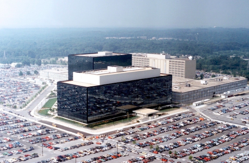
The US National Security Agency (NSA), Fort Meade (Maryland), is considered the largest and most closed US intelligence agency. In the autumn of 1952, a memorandum on the formation of the NSA was signed by President Truman. The establishment of a new body was classified as “secret” and only in 1957 did it appear in the directory of US government agencies. There were even jokes about this, the name “NSA” was decoded as “No Such Agency” (there is no such agency), “Never Say Anything” (never say anything).
Ensuring the national security of the United States and all state communications is the main task of the "non-existent" agency. Interception and cryptanalysis, the creation and application of measures of cryptographic protection, the development of codes and encryption systems, the creation and introduction of special communication equipment are components of the work of a top-secret institution.
Depending on the required (and acceptable) level of security, the NSA has defined various types of encryption. The smaller the number, the higher the level of security. For example: Type 1 products are intended for use by the US government as classified material. Known 1, 2, 3, 4 types of products:
')
1. TOP SECRET
These include algorithms such as AES (256), BATON, FIREFLY, HAVEQUICK and SAVILLE, used in STU-III and in many KG-84, KIV-7, KY-57 and KY-99 military communication devices.
2. National Information Security
Includes products such as CORDOBA, KEA and SKIPJACK used in Cypris cypto equipment and Fortezza (Plus) cryptocards.
3. Unclassified government or commercial information
Approved (unclassified) DES, Tripple DES 1, AES, DSA and SHA algorithms.
4. Commercial cryptographic equipment not for government use.
Here is an incomplete list of devices that were supposedly (partially) developed for / for the NSA:
The KL-7 is an electromechanical rotor cryptomachine developed by the National Security Agency (NSA) in the United States. It was commissioned in 1952, for many years served as the main encryption machine for the United States and NATO. The relatively lightweight (9.3 kg) KL-7 makes it possible to consider it a more advanced version of the German car Enigma. In wartime, she replaced SIGABA (ECM Mark II) in the UK and Canada, as well as CCM and Typex British cars.
SIGABA (ECM Mark II)
Initially, the car was named AFSAM-7, but in the early 1960s it was replaced by TSEC / KL-7. The device, depending on the level of secrecy of the keys, bore the code names ADONIS (high level) and POLLUX (low level). KL-7 was removed from service in 1983.
Unlike the Enigma, the KL-7 had eight rotors, seven of which were placed in one stepping module. Machines were produced in several versions and used by the US Army, Navy and NATO for many years.
Unfortunately, the KL-7 is still a secret device and only a few copies survive to this day. Most of the cars that are on display today were “cleaned” (without electrical wiring).
Despite the secrecy of the KL-7 and its history, over time the information partially becomes available, the NSA releases more and more historical documents, as a result of which researchers manage to figure out the technical details of the machine. In 2011, the crypto-historian Dirk Rymannat from Belgium, thanks to computer modeling (under Windows), managed to recreate the KL-7, and in 2013, the JAVA-simulator KL-7 from MIT (USA) appeared.
KL-7 remained in service until the 1970s. In some countries, for many years, KL-7 machines served as backup devices until they were finally withdrawn from service in 1983. The last message was sent on June 30, 1983 by the Canadian Navy. The KL-7 was replaced by a series of electronic machines known as KW-26, KW-37, KL-51 (RACE) and Aroflex.
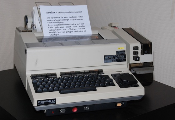
Aroflex
The KL-7 machine consisted of the following basic elements:
KLX-7 . I / O interface for 5-level (teleprinter) data. It consists of two blocks: one is installed between the keyboard and the base unit, the second is behind the rotor basket.
EZ-KL7 . An additional unit developed by the German army (Bundeswehr), allowing two KL-7 machines to work in tandem for error detection. EX-KL7 was installed in front of the keyboard.
KL-7 was an electromechanical rotor cryptomachine, controlled by electronic circuits with gate valves (vacuum valves). The device was powered from an external DC source of 24 V, in fact, as a power supply or battery, for example, a truck. For the synchronous operation of the machine, there was in response a complex mechanical assembly consisting of several rotating parts connected by a common axis. The diagram below shows exactly how this happened. The main engine of 24 V worked with a frequency of rotation of 6600 rpm. He ran the mechanical parts as well as the alternator, which provided 400 V to control the valves / gate valves.
When you press a specific key on the keyboard containing 26 pulse transmission lines (due to a mode switch), a pulse was delivered to the rotors, and then to one of the 26 pulse generator coils. The pulses were fed to the printing device. Since all the rotating parts (dc motor, alternator, pulse generator, printer and stepper module) were connected, everything worked in sync.
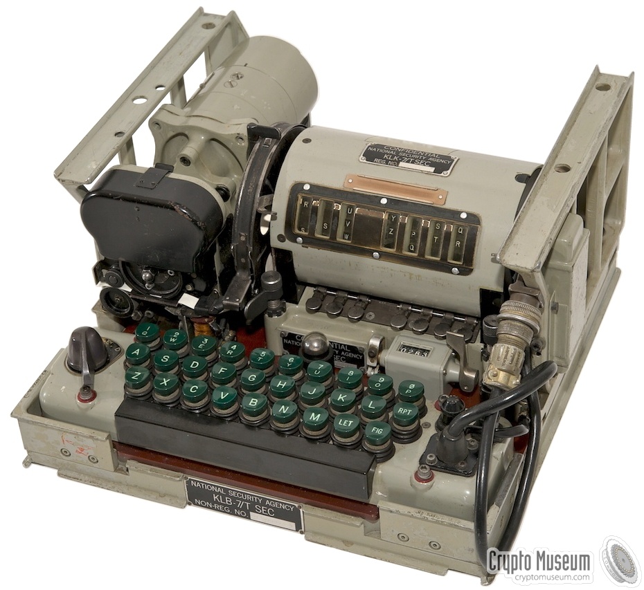
The KLB-7 was actually the undercarriage on which the machine was built, including electronic circuits and a (mechanical) transmission system. The latter consisted of an engine, a synchronization unit, a printer, etc. Please note that the KLB-7 was not (never) a secret element. Apparently, the electromechanical base module was not considered as such, which was able to issue cryptographic secrets.
The rotors of the KL-7 resemble the rotors of the famous German machine Enigma and other cryptomachines on a rotor basis. Each rotor (disk) had electrical contacts on the left and on the right. On the disc there was an adjustable index ring with letters of the alphabet on it and an inner part that connected the contacts on one side with the contacts on the other side. However, there were some significant differences from Enigma.
First of all, the KL-7 rotor had 36 contacts, while the Enigma rotor had 26 contacts. Of the 36 contacts, 26 were used to encrypt 26 letters of the alphabet, and the remaining 10 contacts were used for “looping” when typing (see below). This led to re-encryption of a part of the text (US Patent 2998700, filed by Albert W. Small on September 22, 1944).
Each rotor had an index ring with 36 positions, each of which was divided by a narrow gap. Only 26 positions were identified by letters of the alphabet. The rest are empty. In turn, it looks like this:

Another important difference from Enima is the absence of a reflector (Umkehrwalze). In coding mode, one side of the rotor basket is the entrance and the other side is the output. In the decoding mode - due to the change of contacts - on the contrary. However, the replacement of all contacts is a rather complicated “procedure”; a whole complex of multi-contact switches integrated into the KL-7 keyboard was involved.
The drum with rotors or rotor basket KL-7 was a metal box containing 8 wheels on the spindle (KLK-7). The fourth wheel on the left was fixed in place. It never rotated and, therefore, had no window, and did not show its setting. This wheel was sometimes called the NSA rotor. For each of the other 7 wheels in the drum there was a window. Through this window three consecutive letters of the rotor were visible. The upper letter is the current setting, the position was indicated by a white line, the reading occurred from left to right.
Each KL-7 was shipped with 12 rotors labeled AL in a metal box. The L-rotor was the so-called fixed wheel NSA used in position 4. Of the remaining 11 rotors (AK), 7 were inserted into the rotor drum according to the code book: on a certain day, in a specific order.
The user could remove the rotor drum, freeing two levers on both sides. After removing the right wall of the drum was disconnected and the rotors could be removed from the spindle. The spindle itself remained at the same time inside, since it was attached to the left wall, which, in turn, was attached to the cylindrical drum itself.
Each wheel had 36 contacts on both sides, but only 26 of them were used to encrypt 26 letters of the Latin alphabet. The remaining 10 contacts looped from the right end plate to the left, which caused the recoding. This principle is known as “return” and was coined during World War II by Albert W. Small, during his work in the intelligence service of the US Army (ASIS), when he tried to decode the Japanese crypto machine PURPLE cipher.
US patent 2,984,700 for invention was filed by a scientist on September 22, 1944. Since the invention was considered to belong to the US Army, the patent was classified and was secretly classified until May 16, 1961. In the meantime, inventor Boris Hagelin put forward a similar idea, successfully patented it on October 16, 1953. The existence of an earlier (secret) patent in no way affected the process and Hagelin received a patent 2,802,047 on August 6, 1957. Hagelin intended to use the re-entry principle for his HX encryption machine. To his surprise, the same patent was rejected in Japan. He was simply unaware of the existence of a secret patent.
Although Hagelin argued that this was entirely his idea, it is quite possible (if not likely) that the idea came to him after he had dealt with the KL-7 cryptomachine machine in the early 1950s and discussed its properties with the German main cryptographer Erich Huttenhayn Bonn (1952). The principle of re-entry was used in the Soviet M-125 Violet.
The KL-7 rotors are identical to the rotors used in the UK Singlet BID / 60. It is possible that the encryption wheels were a joint production of the US / UK, or the Americans allowed the British to use rotors from the KL-7 in the British cipher machine. In any case, Singlet rotors were made in the UK.
The British Singlet had 10 rotors (instead of 8), but it was reported that they are compatible with the KL-7, and can use the same eight rotors, two of which will be soothers.
Each KL-7 rotor contained 36 connections, connecting through flat contacts on one side with spring-loaded contacts on the other side, apparently in a random arrangement. The connection of the KL-7 rotors has always been kept secret whether there was any point in this - it remains to be seen.
For safety reasons, it was forbidden to monitor the rotor connection of the KL-7. Even the technical personnel involved in repairing the crypto device did not have the right to track each contact to identify and eliminate the faulty connection. It was only allowed to install spring-loaded contacts on a conductive (metal) surface and check each flat contact. Faulty rotors were never opened; they had to be returned to the NSA for repair.
If you manage to find the KL-7 and trace the rotor connections, the sense of this will be exactly “0”, since the rotor connections for different users were different and often changed for security reasons. Nevertheless, over the years, the Soviet Union successfully read information about the movements of US Navy submarines (encrypted on KL-7).
The rotors were held in position with the help of the locking levers. This spring-loaded levers, located under the rotors. At the end of the lever, there is a small sharp wedge that entered the groove between the desired letters on the rotor circumference. Closer to the front in the lower part of the rotor drum were "shipping" levers. They were set in motion by the main mechanism and blocked in the intervals on the index rotor. Their forward movement rotates the rotor to the next position. With one keystroke, the rotor could take only one step.
Whether the rotor would move when the key was pressed depended on the presence or absence of a notch on the stepping ring on one of the rotors. The stepping ring of each rotor was determined by a switch (3) located in front of the rotor drum.
Interestingly, the switch defined the 10th position of the step ring on the rotor circumference. In other words: when the rotor was at point A (visible in the window on the white line), the switch defined the notch before the letter H (that is, 10 position after A). The switch, in turn, activated the solenoid (L1 - L7), as a result, the rotor rotated.
When setting the daily key, the initial position of the rotors could be changed manually: by pressing the keys, while in plaintext mode (P). When the key was pressed briefly, the rotor moved one step. Holding the key pressed, the rotor made steps continuously.
The control of the rotor movement was a whole complex, and was fixed by internal connection (wiring). Details about the device of the stepper mechanism of the rotors were never published, but in 2011 the Crypto Museum was able to restore the scheme below using the deduction method while the machine was in operation:
Please note that the switches at the top are in the proper order (from 1 to 7), and the order of manual step switches and solenoids are intermixed. This is done in order not to overload the circuit. The step module presented here is implemented in the KL-7 Dirk Rijmenants simulator, the correctness of which is confirmed by former users.
The KL-7 keyboard is part of the KLB-7 base module. It consisted of 29 green keys and a black stripe. There was a standard QWERTY layout, divided into three rows. The numbers were separated by the top line. In the lower right corner were 3 special keys, marked as LET, FIG and RPT.
Each key was actually an electrical switch consisting of a contact and a spring installed under the key. Each time the key was pressed, the contact was grounded (that is, connected to 0V), allowing the pulse generator to give a pulse.
When entering numbers, the user first had to press the FIG key (numbers). It acted as a replacement key on a modern computer. While the car was in the numbers mode, a large neon lamp behind the keyboard was burning. To return to the letter values, you first had to press the LET key.
The coded message KL-7 consisted only of 26 letters of the Latin alphabet. For the source text to contain letters, numbers and spaces, it was necessary to use special techniques. This was done by converting / replacing some letters while clamping SPACE, LET and FIG.
In addition, when switching from encoding to decoding operations (SPACE, LET and FIG) should have been canceled. All this was done using the MODE switch, which was located under the keyboard. The MODE switch was a large board made of electrically insulating laminated pressed material, with contacts on both sides (very much like a printed circuit board, but thicker).
To control the switch, to the left of the keyboard was a knob. The MODE switch had 4 positions: Off (O), paintext (P), encoding (E) and decoding (D).
The mode switch is actually a large slide switch. As the knob was rotated, the large brown getinax board moved from right to left. As mentioned earlier, there were various provisions.
At the heart of the KL-7 is a very compact but complex mechanical module. It consisted of a DC motor and a high voltage alternator, a printing device, a pulse generator, and a synchronization module. All devices were driven by a DC motor, either directly or with 3: 1 gears.
The engine and the generator were installed on the same axis, the rotation speed was 6,600 rpm (revolutions per minute). Thanks to the gear mechanism (3: 1), the pulse generator and printing device were set in motion, and their rotation speed was 2200 rpm. The synchronization module was also set in motion.
Unlike other components, the synchronization module did not rotate continuously. It was also driven by a KLA-7 stepper module (and, therefore, rotors). On each revolution, the rotors could move one position.
The module complex was located in the left half of the KL-7, as shown in the figure. The engine was located behind the module (on the right in the image). Directly in front of the engine is a generator (sometimes called an inverter) with two large bolts at the top.
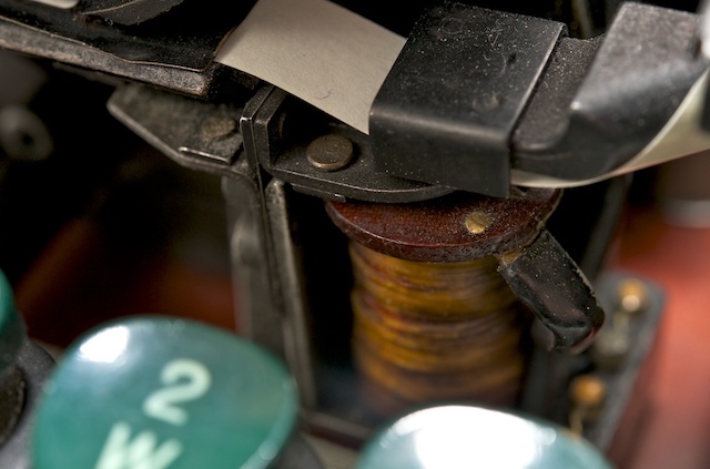
Synchronization with the printer was due to a pulse generator, which was connected to all other rotating parts of the main device module. The pulse generator consisted of 36 coils, divided into two rings, with a rotating magnet in the center. 26 coils were used for 26 letters of the alphabet. The remaining 10 coils are for numbers. Each of them was connected in series with one of the letters, but was mounted on the ring at a slightly different angle. This led to a short delay in the number mode (FIG), which allowed enough time to select the next character on the printing wheel.
The KL-7 was designed with an integrated printer with a continuously rotating print head. The output was printed on a narrow paper strip of 9.5 mm (3/8 "), by analogy as in the American M-209 and the Soviet Violet.
Letters and numbers were placed on the circumference of the print head. When the letter was printed (i.e., the impulse generator gave an impulse), the paper tape moved one position and the squeezing hammer dropped.
Synchronization was guaranteed, since the pulse generator and the print head were controlled by a single axis. A small ribbon was hidden under the black cover; it passed between the print head and the paper ribbon.
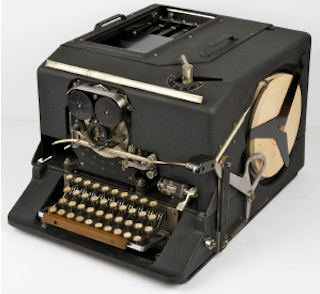
The design of the printer can be said to be identical to the design of the printer in SIGABA, the predecessor of the wartime KL-7. Like the KL-7, it had a rotating print head with two coloring ribbon coils.
The work of the KL-7 is not considered one of the most reliable machines. In fact, her reputation was notorious because of the numerous problems associated with its operation. Many former users recall their “struggle” with KL-7 in order to properly (de) encode messages on it.
The German Bundeswehr even developed an assembly, known as the EZ-KL7, which allowed the two machines to work in tandem (in parallel) to detect errors. The EZ-KL7 unit was installed in front of the keyboard of one of the two KL-7 machines and constantly compared their findings. As soon as a difference was detected, an alarm was raised. Please note that EZ-KL7 is pronounced “Easy KL-7”.
This option required the installation of the KLX-7 I / O interface.
By itself, the KL-7 received input information only through the built-in keyboard, and displayed information in the form of printed text on a 9.5 mm paper tape. To connect the KL-7 directly to the teleprinter, the KLX-7 I / O interface was available. As far as we know, the KLX-7 consisted of two parts, one of which was installed between the keyboard and the base.
All this required the removal of the keyboard, and in its place was installed contact module. Later, the keyboard was made removable, now it could be placed on top of the contact module. In reality, the I / O interface was installed on the back of the machine, behind the drum with the rotors.
Are classified as - drum with rotors (KLK-7 / TSEC), stepping mechanism (KLA-7 / TSEC) and electrical circuit. All other modules of the device are free from the neck "secret". Given the age of KL-7 and the fact that more and more principles of the operation of the crypto machine are becoming clear to researchers, it is assumed that in the near future it will be completely declassified. Recently, the NSA released a document that describes the history of the development of KL-7.
During its lifetime, the KL-7 was at risk several times. It is believed that in the Soviet Union they were able to intercept and decipher KL-7 messages.
The most famous story is the story of John Anthony Walker, born in 1937, who worked in the US Navy and successfully spied on the side of the USSR for almost 17 years. Walker joined the US Navy in 1955 and became a Soviet spy from December 1967, explaining everything with financial difficulties in life. From that moment, right up to his retirement from the Navy (1983), he provided the USSR with keylists and other critical encryption materials KL-47, KW-7 and other cryptomachines.
For the information provided, he received several thousand dollars every month. In 1969, he began to look for help in his espionage business and became friends with Jerry Whitworth, a student who later became a senior fleet officer. In 1973, Anthony was able to enlist his help. In 1984, the circle of his spies was replenished with new members - elder brother Arthur and son Michael. Walker tried to attract his daughter, a newly minted employee in the US Army, but she dropped out of the game, becoming pregnant and abandoning a military career.
In 1976, Walker and his wife Barbara divorced because of beatings and alcohol abuse by Walker. Walker refused to pay alimony (1985) and Barbara turned him in to the FBI, which ultimately led to his arrest. After his arrest, Walker collaborated with the authorities and made a plea bargain to lower the sentence to his son Michael. Suffering from diabetes and throat cancer, John Walker died in prison on August 28, 2014. His son Michael was released on parole in February 2000.
Information transmitted by John Walker and his espionage group allowed the USSR to build an analogue of the KL-7. As a result, at least a million secret messages were decrypted (TOP SECRET). The analogue KL-7 was even equipped with a small device called a rotary reader, which made it easy to trace the internal wiring of each rotor.
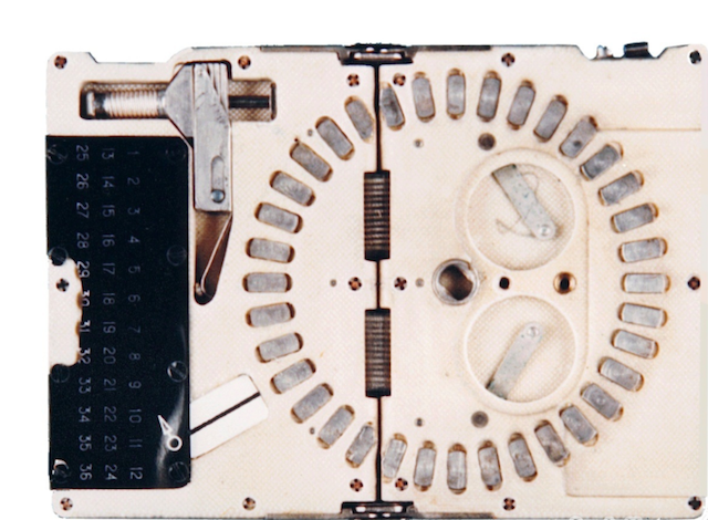
The photo above shows the device itself, although it was confiscated by the FBI. Small enough to carry it unnoticed and easily hidden in a pocket. When folded, its dimensions were 7.5 x 10 cm (such as a pack of cigarettes).
KL-7 was compromised again in its history. Here is how it was. During the Vietnam War (1970), Americans decided to provide the Republic of Vietnam (RVN) with a limited amount of cryptographic equipment: M-209 and KL-7 encryption machines, various One-Time Pad (OTP) systems, voice authentication codes and NESTOR ( KY-8).
After the withdrawal of US troops from Vietnam, the base with cryptographic equipment and the American employees in charge of this equipment, known as Don Vi '600, remained in place. In late 1974 and early 1975, the situation worsened, and the Americans began to withdraw some of the equipment with the intention of sending it back to CONUS or Hawaii.
In January - February, the situation became critical, it was decided to immediately divert equipment from the Don Vi '600 and ship it to CONUS.In three weeks, about 700 pieces of ADONIS and NESTOR equipment were prepared for shipment to CONUS, but unfortunately, none of these devices were sent or destroyed on time. In the end, the equipment fell into the hands of North Vietnam.
It is likely that the North Vietnamese eventually sold some of the machines of the USSR and the Chinese, along with key materials (received over 12 months) and One-Time Pad (OTP) systems.
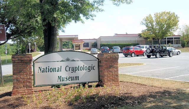
The National Cryptography Museum (created by the NSA) has become home to many exhibits that lift the veil of secrecy and fill in the gaps in the history of cryptography from the days of the War of Independence to the present day.
The source was the amazing work of Cypto Museum .
Thank you for staying with us. Do you like our articles? Want to see more interesting materials?Support us by placing an order or recommending to friends, 30% discount for Habr's users on a unique analogue of the entry-level servers that we invented for you: The whole truth about VPS (KVM) E5-2650 v4 (6 Cores) 10GB DDR4 240GB SSD 1Gbps from $ 20 or how to share the server? (Options are available with RAID1 and RAID10, up to 24 cores and up to 40GB DDR4 RAM).
Dell R730xd 2 times cheaper? Only we have 2 x Intel Dodeca-Core Xeon E5-2650v4 128GB DDR4 6x480GB SSD 1Gbps 100 TV from $ 249 in the Netherlands and the USA! Read about How to build an infrastructure building. class c using servers Dell R730xd E5-2650 v4 worth 9000 euros for a penny?
Ensuring the national security of the United States and all state communications is the main task of the "non-existent" agency. Interception and cryptanalysis, the creation and application of measures of cryptographic protection, the development of codes and encryption systems, the creation and introduction of special communication equipment are components of the work of a top-secret institution.
Depending on the required (and acceptable) level of security, the NSA has defined various types of encryption. The smaller the number, the higher the level of security. For example: Type 1 products are intended for use by the US government as classified material. Known 1, 2, 3, 4 types of products:
')
1. TOP SECRET
These include algorithms such as AES (256), BATON, FIREFLY, HAVEQUICK and SAVILLE, used in STU-III and in many KG-84, KIV-7, KY-57 and KY-99 military communication devices.
2. National Information Security
Includes products such as CORDOBA, KEA and SKIPJACK used in Cypris cypto equipment and Fortezza (Plus) cryptocards.
3. Unclassified government or commercial information
Approved (unclassified) DES, Tripple DES 1, AES, DSA and SHA algorithms.
4. Commercial cryptographic equipment not for government use.
Here is an incomplete list of devices that were supposedly (partially) developed for / for the NSA:
- HY-2 - narrowband voice coder
- STU-I is a first generation digital safe telephone device (STU)
- STU-II - second generation telephone (STU)
- STU-III - the last of a series of digital telephones (STU)
- STE - telephone set providing voice and data protection through ISDN and PSTN telephone lines
- KL-7 - Rotary Encryption Machine
- KW-7 - highly reliable online crypto machine
- KG-13 - universal digital transistor full-duplex key generator
- KW-26 - a large electronic encryption machine
- KG-84 - military digital encoder
- Fortezza - equipment safety module (HSM), which is implemented as a PCMCIA card
- FLYBALL modules - functional electronic circuits
Crypto KL-7
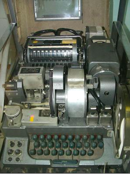
The KL-7 is an electromechanical rotor cryptomachine developed by the National Security Agency (NSA) in the United States. It was commissioned in 1952, for many years served as the main encryption machine for the United States and NATO. The relatively lightweight (9.3 kg) KL-7 makes it possible to consider it a more advanced version of the German car Enigma. In wartime, she replaced SIGABA (ECM Mark II) in the UK and Canada, as well as CCM and Typex British cars.
SIGABA (ECM Mark II)
Initially, the car was named AFSAM-7, but in the early 1960s it was replaced by TSEC / KL-7. The device, depending on the level of secrecy of the keys, bore the code names ADONIS (high level) and POLLUX (low level). KL-7 was removed from service in 1983.
Unlike the Enigma, the KL-7 had eight rotors, seven of which were placed in one stepping module. Machines were produced in several versions and used by the US Army, Navy and NATO for many years.
Unfortunately, the KL-7 is still a secret device and only a few copies survive to this day. Most of the cars that are on display today were “cleaned” (without electrical wiring).
Despite the secrecy of the KL-7 and its history, over time the information partially becomes available, the NSA releases more and more historical documents, as a result of which researchers manage to figure out the technical details of the machine. In 2011, the crypto-historian Dirk Rymannat from Belgium, thanks to computer modeling (under Windows), managed to recreate the KL-7, and in 2013, the JAVA-simulator KL-7 from MIT (USA) appeared.
KL-7 remained in service until the 1970s. In some countries, for many years, KL-7 machines served as backup devices until they were finally withdrawn from service in 1983. The last message was sent on June 30, 1983 by the Canadian Navy. The KL-7 was replaced by a series of electronic machines known as KW-26, KW-37, KL-51 (RACE) and Aroflex.
Aroflex
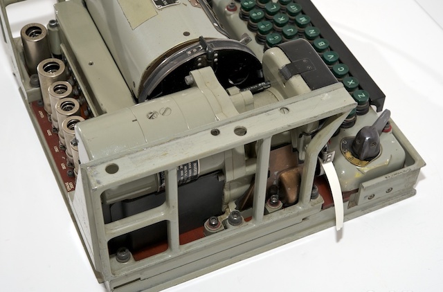
Components of the device
The KL-7 machine consisted of the following basic elements:
- The KLB-7 is a basic module consisting of an engine, a generator and electronics (valves or vacuum tubes).
- KLK-7 - eight KL-7 rotors were placed on the spindle inside the rotor drum (basket). By releasing the two levers, located on both sides of the basket with rotors, it was possible to pull it out of the car.
- OAK-7 - stepping module.
Options
KLX-7 . I / O interface for 5-level (teleprinter) data. It consists of two blocks: one is installed between the keyboard and the base unit, the second is behind the rotor basket.
EZ-KL7 . An additional unit developed by the German army (Bundeswehr), allowing two KL-7 machines to work in tandem for error detection. EX-KL7 was installed in front of the keyboard.
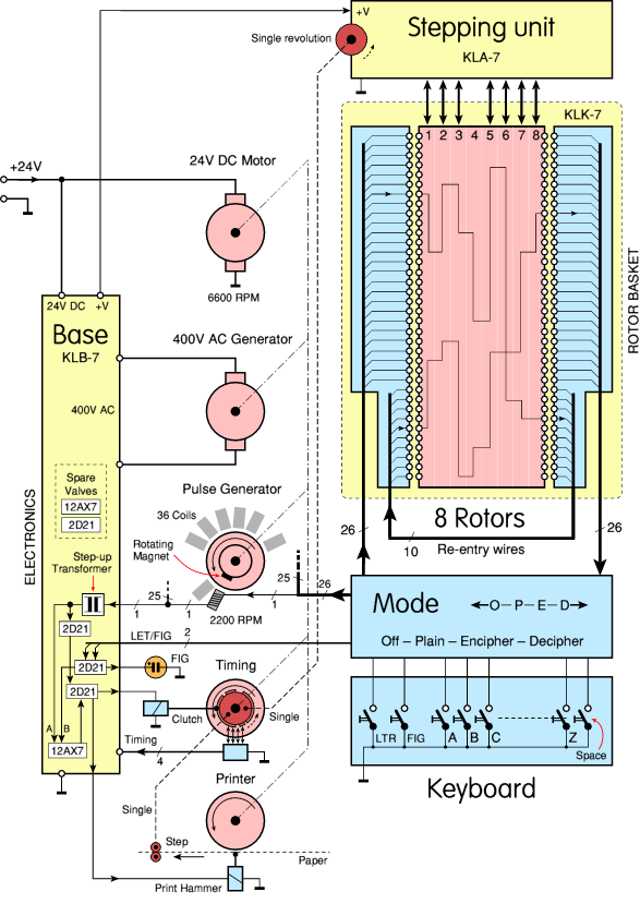
Block diagram
KL-7 was an electromechanical rotor cryptomachine, controlled by electronic circuits with gate valves (vacuum valves). The device was powered from an external DC source of 24 V, in fact, as a power supply or battery, for example, a truck. For the synchronous operation of the machine, there was in response a complex mechanical assembly consisting of several rotating parts connected by a common axis. The diagram below shows exactly how this happened. The main engine of 24 V worked with a frequency of rotation of 6600 rpm. He ran the mechanical parts as well as the alternator, which provided 400 V to control the valves / gate valves.
When you press a specific key on the keyboard containing 26 pulse transmission lines (due to a mode switch), a pulse was delivered to the rotors, and then to one of the 26 pulse generator coils. The pulses were fed to the printing device. Since all the rotating parts (dc motor, alternator, pulse generator, printer and stepper module) were connected, everything worked in sync.
Base module KLB-7
The KLB-7 was actually the undercarriage on which the machine was built, including electronic circuits and a (mechanical) transmission system. The latter consisted of an engine, a synchronization unit, a printer, etc. Please note that the KLB-7 was not (never) a secret element. Apparently, the electromechanical base module was not considered as such, which was able to issue cryptographic secrets.
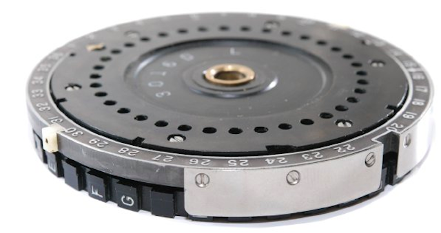
KLK-7 rotors
The rotors of the KL-7 resemble the rotors of the famous German machine Enigma and other cryptomachines on a rotor basis. Each rotor (disk) had electrical contacts on the left and on the right. On the disc there was an adjustable index ring with letters of the alphabet on it and an inner part that connected the contacts on one side with the contacts on the other side. However, there were some significant differences from Enigma.
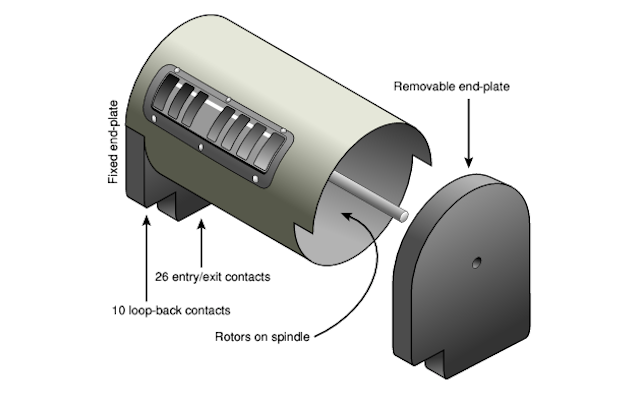
First of all, the KL-7 rotor had 36 contacts, while the Enigma rotor had 26 contacts. Of the 36 contacts, 26 were used to encrypt 26 letters of the alphabet, and the remaining 10 contacts were used for “looping” when typing (see below). This led to re-encryption of a part of the text (US Patent 2998700, filed by Albert W. Small on September 22, 1944).
Each rotor had an index ring with 36 positions, each of which was divided by a narrow gap. Only 26 positions were identified by letters of the alphabet. The rest are empty. In turn, it looks like this:
Another important difference from Enima is the absence of a reflector (Umkehrwalze). In coding mode, one side of the rotor basket is the entrance and the other side is the output. In the decoding mode - due to the change of contacts - on the contrary. However, the replacement of all contacts is a rather complicated “procedure”; a whole complex of multi-contact switches integrated into the KL-7 keyboard was involved.
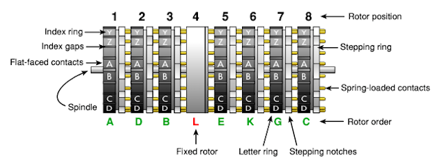
The drum with rotors or rotor basket KL-7 was a metal box containing 8 wheels on the spindle (KLK-7). The fourth wheel on the left was fixed in place. It never rotated and, therefore, had no window, and did not show its setting. This wheel was sometimes called the NSA rotor. For each of the other 7 wheels in the drum there was a window. Through this window three consecutive letters of the rotor were visible. The upper letter is the current setting, the position was indicated by a white line, the reading occurred from left to right.
Each KL-7 was shipped with 12 rotors labeled AL in a metal box. The L-rotor was the so-called fixed wheel NSA used in position 4. Of the remaining 11 rotors (AK), 7 were inserted into the rotor drum according to the code book: on a certain day, in a specific order.
The user could remove the rotor drum, freeing two levers on both sides. After removing the right wall of the drum was disconnected and the rotors could be removed from the spindle. The spindle itself remained at the same time inside, since it was attached to the left wall, which, in turn, was attached to the cylindrical drum itself.
Repeat entry principle
Each wheel had 36 contacts on both sides, but only 26 of them were used to encrypt 26 letters of the Latin alphabet. The remaining 10 contacts looped from the right end plate to the left, which caused the recoding. This principle is known as “return” and was coined during World War II by Albert W. Small, during his work in the intelligence service of the US Army (ASIS), when he tried to decode the Japanese crypto machine PURPLE cipher.
US patent 2,984,700 for invention was filed by a scientist on September 22, 1944. Since the invention was considered to belong to the US Army, the patent was classified and was secretly classified until May 16, 1961. In the meantime, inventor Boris Hagelin put forward a similar idea, successfully patented it on October 16, 1953. The existence of an earlier (secret) patent in no way affected the process and Hagelin received a patent 2,802,047 on August 6, 1957. Hagelin intended to use the re-entry principle for his HX encryption machine. To his surprise, the same patent was rejected in Japan. He was simply unaware of the existence of a secret patent.
Although Hagelin argued that this was entirely his idea, it is quite possible (if not likely) that the idea came to him after he had dealt with the KL-7 cryptomachine machine in the early 1950s and discussed its properties with the German main cryptographer Erich Huttenhayn Bonn (1952). The principle of re-entry was used in the Soviet M-125 Violet.
British Singlet BID / 60
The KL-7 rotors are identical to the rotors used in the UK Singlet BID / 60. It is possible that the encryption wheels were a joint production of the US / UK, or the Americans allowed the British to use rotors from the KL-7 in the British cipher machine. In any case, Singlet rotors were made in the UK.
The British Singlet had 10 rotors (instead of 8), but it was reported that they are compatible with the KL-7, and can use the same eight rotors, two of which will be soothers.
Rotor connection
Each KL-7 rotor contained 36 connections, connecting through flat contacts on one side with spring-loaded contacts on the other side, apparently in a random arrangement. The connection of the KL-7 rotors has always been kept secret whether there was any point in this - it remains to be seen.
For safety reasons, it was forbidden to monitor the rotor connection of the KL-7. Even the technical personnel involved in repairing the crypto device did not have the right to track each contact to identify and eliminate the faulty connection. It was only allowed to install spring-loaded contacts on a conductive (metal) surface and check each flat contact. Faulty rotors were never opened; they had to be returned to the NSA for repair.
If you manage to find the KL-7 and trace the rotor connections, the sense of this will be exactly “0”, since the rotor connections for different users were different and often changed for security reasons. Nevertheless, over the years, the Soviet Union successfully read information about the movements of US Navy submarines (encrypted on KL-7).
Step module
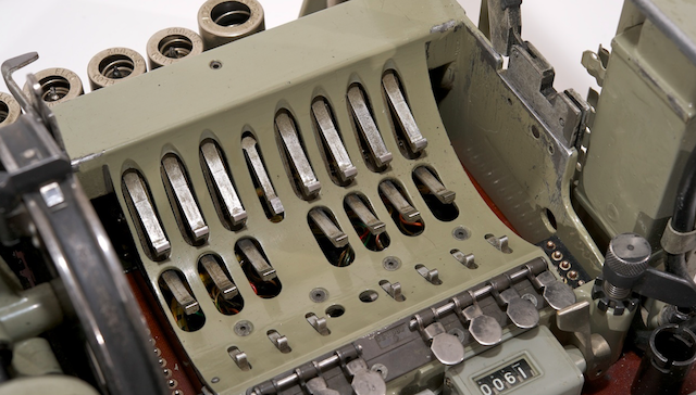
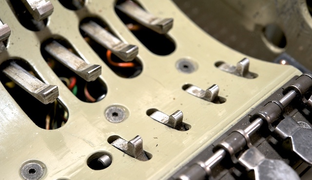
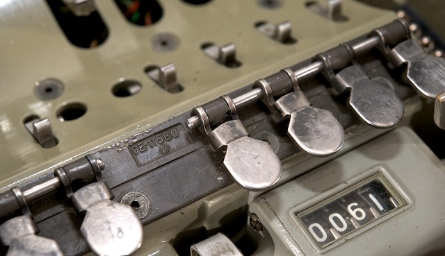
The rotors were held in position with the help of the locking levers. This spring-loaded levers, located under the rotors. At the end of the lever, there is a small sharp wedge that entered the groove between the desired letters on the rotor circumference. Closer to the front in the lower part of the rotor drum were "shipping" levers. They were set in motion by the main mechanism and blocked in the intervals on the index rotor. Their forward movement rotates the rotor to the next position. With one keystroke, the rotor could take only one step.
Whether the rotor would move when the key was pressed depended on the presence or absence of a notch on the stepping ring on one of the rotors. The stepping ring of each rotor was determined by a switch (3) located in front of the rotor drum.
Interestingly, the switch defined the 10th position of the step ring on the rotor circumference. In other words: when the rotor was at point A (visible in the window on the white line), the switch defined the notch before the letter H (that is, 10 position after A). The switch, in turn, activated the solenoid (L1 - L7), as a result, the rotor rotated.
When setting the daily key, the initial position of the rotors could be changed manually: by pressing the keys, while in plaintext mode (P). When the key was pressed briefly, the rotor moved one step. Holding the key pressed, the rotor made steps continuously.
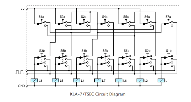
Stepper mechanism of the rotors
The control of the rotor movement was a whole complex, and was fixed by internal connection (wiring). Details about the device of the stepper mechanism of the rotors were never published, but in 2011 the Crypto Museum was able to restore the scheme below using the deduction method while the machine was in operation:
Please note that the switches at the top are in the proper order (from 1 to 7), and the order of manual step switches and solenoids are intermixed. This is done in order not to overload the circuit. The step module presented here is implemented in the KL-7 Dirk Rijmenants simulator, the correctness of which is confirmed by former users.
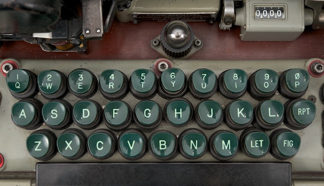
Keyboard
The KL-7 keyboard is part of the KLB-7 base module. It consisted of 29 green keys and a black stripe. There was a standard QWERTY layout, divided into three rows. The numbers were separated by the top line. In the lower right corner were 3 special keys, marked as LET, FIG and RPT.
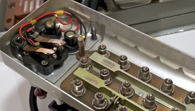
Each key was actually an electrical switch consisting of a contact and a spring installed under the key. Each time the key was pressed, the contact was grounded (that is, connected to 0V), allowing the pulse generator to give a pulse.
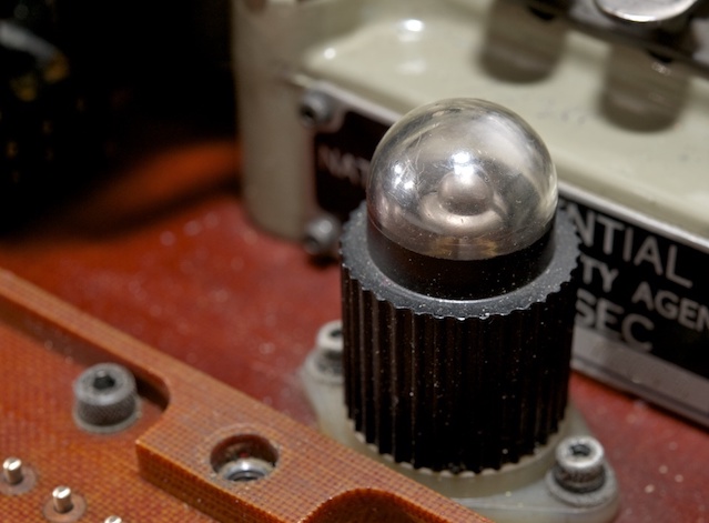
When entering numbers, the user first had to press the FIG key (numbers). It acted as a replacement key on a modern computer. While the car was in the numbers mode, a large neon lamp behind the keyboard was burning. To return to the letter values, you first had to press the LET key.
Mode switch
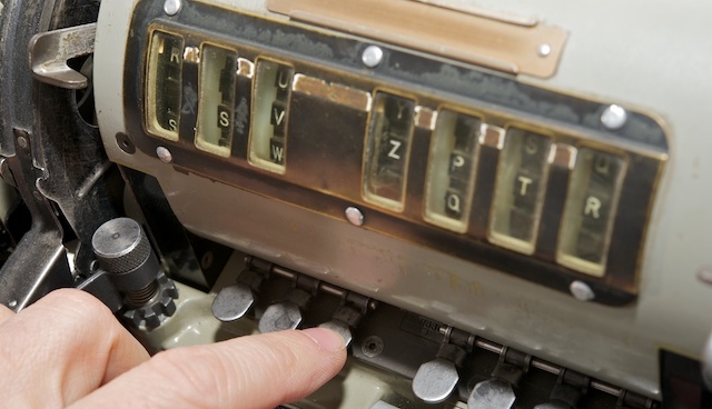
The coded message KL-7 consisted only of 26 letters of the Latin alphabet. For the source text to contain letters, numbers and spaces, it was necessary to use special techniques. This was done by converting / replacing some letters while clamping SPACE, LET and FIG.
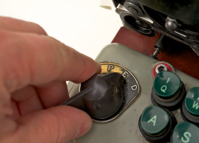
In addition, when switching from encoding to decoding operations (SPACE, LET and FIG) should have been canceled. All this was done using the MODE switch, which was located under the keyboard. The MODE switch was a large board made of electrically insulating laminated pressed material, with contacts on both sides (very much like a printed circuit board, but thicker).
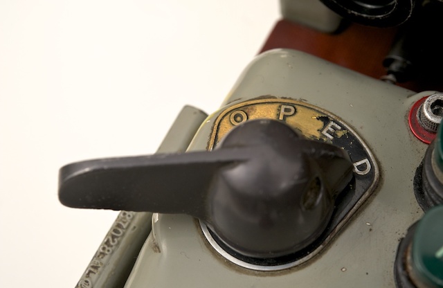
To control the switch, to the left of the keyboard was a knob. The MODE switch had 4 positions: Off (O), paintext (P), encoding (E) and decoding (D).
The mode switch is actually a large slide switch. As the knob was rotated, the large brown getinax board moved from right to left. As mentioned earlier, there were various provisions.
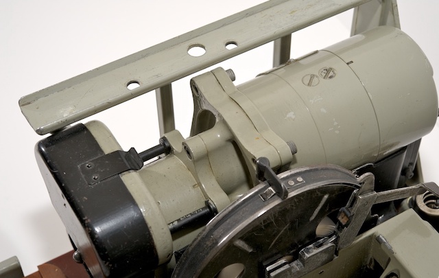
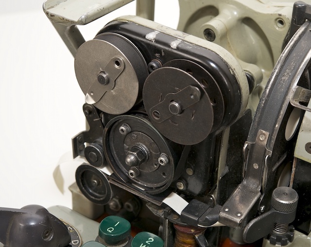
Device module
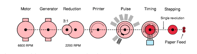
At the heart of the KL-7 is a very compact but complex mechanical module. It consisted of a DC motor and a high voltage alternator, a printing device, a pulse generator, and a synchronization module. All devices were driven by a DC motor, either directly or with 3: 1 gears.
The engine and the generator were installed on the same axis, the rotation speed was 6,600 rpm (revolutions per minute). Thanks to the gear mechanism (3: 1), the pulse generator and printing device were set in motion, and their rotation speed was 2200 rpm. The synchronization module was also set in motion.
Unlike other components, the synchronization module did not rotate continuously. It was also driven by a KLA-7 stepper module (and, therefore, rotors). On each revolution, the rotors could move one position.
The module complex was located in the left half of the KL-7, as shown in the figure. The engine was located behind the module (on the right in the image). Directly in front of the engine is a generator (sometimes called an inverter) with two large bolts at the top.
Pulse generator
Synchronization with the printer was due to a pulse generator, which was connected to all other rotating parts of the main device module. The pulse generator consisted of 36 coils, divided into two rings, with a rotating magnet in the center. 26 coils were used for 26 letters of the alphabet. The remaining 10 coils are for numbers. Each of them was connected in series with one of the letters, but was mounted on the ring at a slightly different angle. This led to a short delay in the number mode (FIG), which allowed enough time to select the next character on the printing wheel.
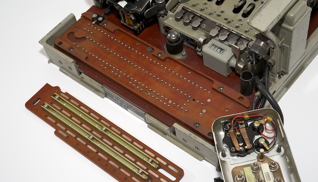
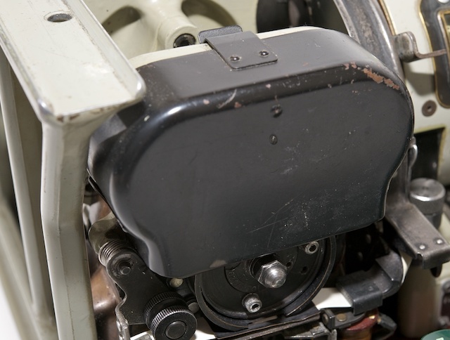
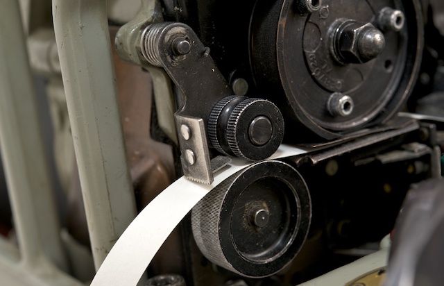
Printing device
The KL-7 was designed with an integrated printer with a continuously rotating print head. The output was printed on a narrow paper strip of 9.5 mm (3/8 "), by analogy as in the American M-209 and the Soviet Violet.
Letters and numbers were placed on the circumference of the print head. When the letter was printed (i.e., the impulse generator gave an impulse), the paper tape moved one position and the squeezing hammer dropped.
Synchronization was guaranteed, since the pulse generator and the print head were controlled by a single axis. A small ribbon was hidden under the black cover; it passed between the print head and the paper ribbon.
The design of the printer can be said to be identical to the design of the printer in SIGABA, the predecessor of the wartime KL-7. Like the KL-7, it had a rotating print head with two coloring ribbon coils.
German tandem version EZ-KL7
The work of the KL-7 is not considered one of the most reliable machines. In fact, her reputation was notorious because of the numerous problems associated with its operation. Many former users recall their “struggle” with KL-7 in order to properly (de) encode messages on it.
The German Bundeswehr even developed an assembly, known as the EZ-KL7, which allowed the two machines to work in tandem (in parallel) to detect errors. The EZ-KL7 unit was installed in front of the keyboard of one of the two KL-7 machines and constantly compared their findings. As soon as a difference was detected, an alarm was raised. Please note that EZ-KL7 is pronounced “Easy KL-7”.
This option required the installation of the KLX-7 I / O interface.
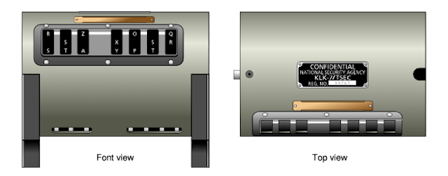
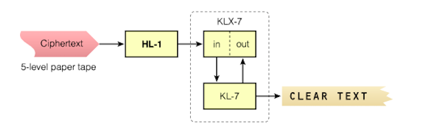
KLX-7 I / O Interface
By itself, the KL-7 received input information only through the built-in keyboard, and displayed information in the form of printed text on a 9.5 mm paper tape. To connect the KL-7 directly to the teleprinter, the KLX-7 I / O interface was available. As far as we know, the KLX-7 consisted of two parts, one of which was installed between the keyboard and the base.
All this required the removal of the keyboard, and in its place was installed contact module. Later, the keyboard was made removable, now it could be placed on top of the contact module. In reality, the I / O interface was installed on the back of the machine, behind the drum with the rotors.
Are classified as - drum with rotors (KLK-7 / TSEC), stepping mechanism (KLA-7 / TSEC) and electrical circuit. All other modules of the device are free from the neck "secret". Given the age of KL-7 and the fact that more and more principles of the operation of the crypto machine are becoming clear to researchers, it is assumed that in the near future it will be completely declassified. Recently, the NSA released a document that describes the history of the development of KL-7.
Incriminating facts
During its lifetime, the KL-7 was at risk several times. It is believed that in the Soviet Union they were able to intercept and decipher KL-7 messages.
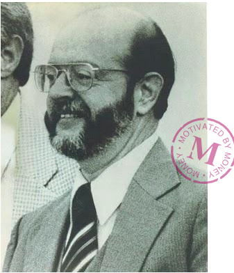
The most famous story is the story of John Anthony Walker, born in 1937, who worked in the US Navy and successfully spied on the side of the USSR for almost 17 years. Walker joined the US Navy in 1955 and became a Soviet spy from December 1967, explaining everything with financial difficulties in life. From that moment, right up to his retirement from the Navy (1983), he provided the USSR with keylists and other critical encryption materials KL-47, KW-7 and other cryptomachines.
For the information provided, he received several thousand dollars every month. In 1969, he began to look for help in his espionage business and became friends with Jerry Whitworth, a student who later became a senior fleet officer. In 1973, Anthony was able to enlist his help. In 1984, the circle of his spies was replenished with new members - elder brother Arthur and son Michael. Walker tried to attract his daughter, a newly minted employee in the US Army, but she dropped out of the game, becoming pregnant and abandoning a military career.
In 1976, Walker and his wife Barbara divorced because of beatings and alcohol abuse by Walker. Walker refused to pay alimony (1985) and Barbara turned him in to the FBI, which ultimately led to his arrest. After his arrest, Walker collaborated with the authorities and made a plea bargain to lower the sentence to his son Michael. Suffering from diabetes and throat cancer, John Walker died in prison on August 28, 2014. His son Michael was released on parole in February 2000.
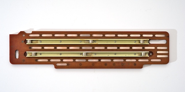
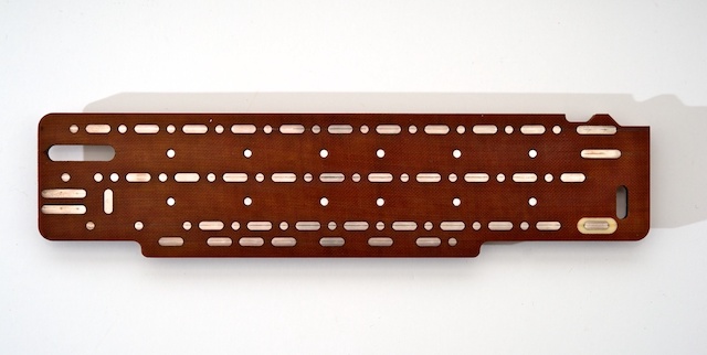
Information transmitted by John Walker and his espionage group allowed the USSR to build an analogue of the KL-7. As a result, at least a million secret messages were decrypted (TOP SECRET). The analogue KL-7 was even equipped with a small device called a rotary reader, which made it easy to trace the internal wiring of each rotor.
The photo above shows the device itself, although it was confiscated by the FBI. Small enough to carry it unnoticed and easily hidden in a pocket. When folded, its dimensions were 7.5 x 10 cm (such as a pack of cigarettes).
Lost in vietnam
KL-7 was compromised again in its history. Here is how it was. During the Vietnam War (1970), Americans decided to provide the Republic of Vietnam (RVN) with a limited amount of cryptographic equipment: M-209 and KL-7 encryption machines, various One-Time Pad (OTP) systems, voice authentication codes and NESTOR ( KY-8).
After the withdrawal of US troops from Vietnam, the base with cryptographic equipment and the American employees in charge of this equipment, known as Don Vi '600, remained in place. In late 1974 and early 1975, the situation worsened, and the Americans began to withdraw some of the equipment with the intention of sending it back to CONUS or Hawaii.
In January - February, the situation became critical, it was decided to immediately divert equipment from the Don Vi '600 and ship it to CONUS.In three weeks, about 700 pieces of ADONIS and NESTOR equipment were prepared for shipment to CONUS, but unfortunately, none of these devices were sent or destroyed on time. In the end, the equipment fell into the hands of North Vietnam.
It is likely that the North Vietnamese eventually sold some of the machines of the USSR and the Chinese, along with key materials (received over 12 months) and One-Time Pad (OTP) systems.
The National Cryptography Museum (created by the NSA) has become home to many exhibits that lift the veil of secrecy and fill in the gaps in the history of cryptography from the days of the War of Independence to the present day.
The source was the amazing work of Cypto Museum .
Thank you for staying with us. Do you like our articles? Want to see more interesting materials?Support us by placing an order or recommending to friends, 30% discount for Habr's users on a unique analogue of the entry-level servers that we invented for you: The whole truth about VPS (KVM) E5-2650 v4 (6 Cores) 10GB DDR4 240GB SSD 1Gbps from $ 20 or how to share the server? (Options are available with RAID1 and RAID10, up to 24 cores and up to 40GB DDR4 RAM).
Dell R730xd 2 times cheaper? Only we have 2 x Intel Dodeca-Core Xeon E5-2650v4 128GB DDR4 6x480GB SSD 1Gbps 100 TV from $ 249 in the Netherlands and the USA! Read about How to build an infrastructure building. class c using servers Dell R730xd E5-2650 v4 worth 9000 euros for a penny?
Source: https://habr.com/ru/post/346546/
All Articles