Developing a cool GUI on esp8266 with the uGFX library
In many projects for esp8266 I use a touchscreen TFT screen. Depending on the project, the interface can be simple, for example, a text console that displays a log of the application or just a graph of the input signal changes. And in some - a complex GUI, with multiple screens, graphic buttons, text input lines, and even a virtual keyboard.
In this article I want to share my experience on how to connect a touchscreen screen to esp8266 and implement a graphical interface in the Arduino environment.
Video teaser:
So let's get started
The first part, the hardware
Select screen model
Now on the market, read on aliexpress, a huge number of TFT screen models are being sold - in various sizes, with different resolutions, with or without a touchscreen.
TFT screens differ in the method of connection - there are screens that are connected via the SPI bus, while others are connected via a parallel bus.
Minimally, only 4 signal outputs (GPIO) are required for connecting via SPI bus, and for connecting via parallel bus - at least 10 (and this is without considering the touchscreen controller). Connecting via a parallel bus gives great speed, because in one clock cycle, 8 bits of information are transmitted at once, while in SPI only 1 bit is transmitted.
However, with SPI connectivity, there is another advantage - fewer involved pins. In esp8266, the number of required pins is decisive: the number of free GPIOs is limited.
I would single out such most popular modules of TFT screens with an SPI interface:
ili9341, 320x240, 2.4 ", with touchscreen controller linkili9225, 176x220, 2.2, without touchscreen linkst7735, 160x128, 1.8 ", without touchscreen link
Connect TFT screen to esp8266.
Most SPI screens have similar hardware interfaces, and therefore, they connect to the processor in the same way, to the accuracy of small variations in the names. In the plate below is a list of findings - and a description of what they mean:
| Conclusion | Alternative names | Connect to esp8266 | Purpose |
|---|---|---|---|
| SCLK | SCK, SCL | GPIO14 | SPI bus clock |
| SDA | MOSI | GPIO13 | Transferring SPI data from the processor to the screen |
| CS | SS | GPIO5 | Chip selection (multiple devices can be connected to the SPI bus) |
| A0 | RS, D / C | GPIO15 | Selection of data / command transfer mode |
| RESET | Rst | VCC | Hardware reset |
| SDO | Miso | - | Data transfer from the screen to the processor (optional) |
| LED + | LED | VCC | Turn on the backlight |
| VSS | VCC | VCC | Screen power + 3.3V |
| GND | GND | Land |
The RESET and LED+ pins can be connected to the +3.3 volt power bus, however, if desired, they can be connected to the GPIO esp8266, and be able to programmatically control the reset and screen backlight.
Conclusions CS and A0 can be connected to any convenient esp8266 GPIO.
The most important part is the SCLK and SDA pins. They are responsible for transferring data over the SPI bus. They need to be connected to the corresponding pins of the SPI esp8266 controller. These are GPIO14 and GPIO13 respectively.
If the screen has a touchscreen controller, it should also be connected to the SPI bus:
| Conclusion | Connect to esp8266 | Purpose |
|---|---|---|
| T_CLK | GPIO14 | SPI bus clock |
| T_DIN | GPIO13 | Transferring SPI data from the processor to the touchscreen controller |
| T_CS | GPIO16 | Chip selection (multiple devices can be connected to the SPI bus) |
| T_DO | GPIO12 | Data transfer from controller to processor |
| T_IRQ | GPIO4 | Sign of clicking on the touchscreen |
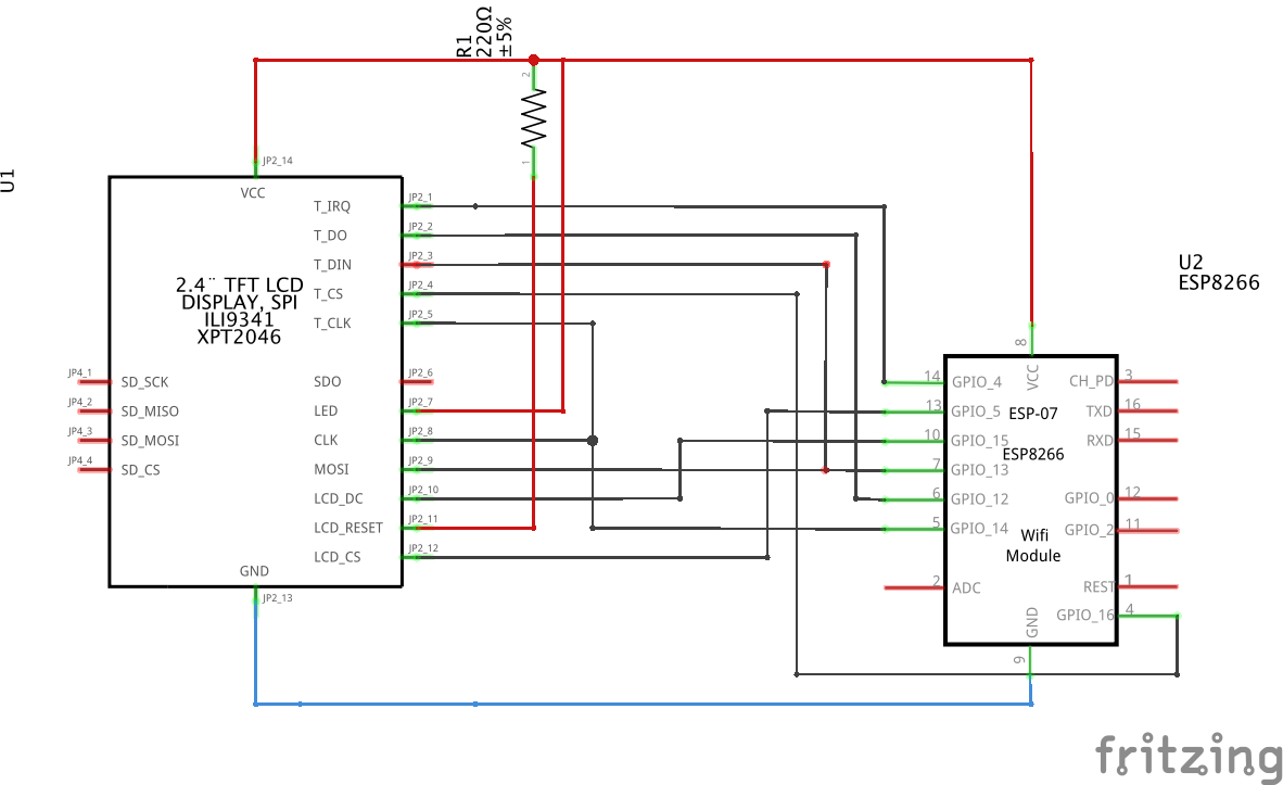
Notice that the esp8266 GPIO14 and GPIO13 connected in parallel to the screen and touchscreen controller. The fact is that several devices can be connected to the SPI bus. The device is selected by setting the logic level 0 on the CS output of the required device.
Screen connection diagram of ili9341 to esp8266
Part two, software
We decided on the screen and the wiring diagram, now it's time to go to the program part. First of all, we will choose the graphic library with which we will implement the GUI.
Having tried several dozen libraries, I chose the uGFX library. In my opinion, this is one of the best graphics libraries for microcontrollers. Rich functionality is combined with modularity and only the required components are included in the project. The library is open source and free for non-commercial use. The library has quality documentation available on the project website.
A big plus of the uGFX library is an advanced font rendering engine, with utf8 support. The kit includes a program for generating fonts from ttf files, including those with Cyrillic.
The library is cross-platform - this means that the GUI part of the application can be assembled for any processor, including esp8266.
Screen and touchscreen drivers are connected by dedicated modules, and if the necessary drivers are not included, you can implement them yourself.
In addition, uGFX studio is included in the uGFX package - WYSWIG interface editor, in which you can visually prepare interface layouts, and uGFX studio will automatically generate code and decompose resources. Unfortunately, now uGFX studio is still in the status of the beta version, and to get a beta, you need to write to the developers on the forum.
And, the final cherry on the cake: the GUI code of the application, you can build under the desktop (Linux / Windows / OSX) and see directly on the computer what the interface will look like.
We connect uGFX to the project
The library uses its build system, which is out of the box not supported by the Arduino build system. But this restriction can be circumvented. I used this article as a reference.
The text below assumes that the Arduino development environment with esp8266 support is already installed and configured. If still not, then about installation and environment setup it is possible to read in this article on geektimes
Now step by step how to connect the library:
- Find the Libraries folder from the Arduino environment. Depending on the platform, it may be located in such places:
OSX-/Users/<username>/Documents/Arduino/libraries/Windows-C:\Users\<username>\My Documents\Arduino\LibrariesLinux-/home/<username>/Documents/Arduino/libraries
Copy or copy uGFX to the Libraries folder. You can download it from here - a version with already built-in Cyrillic fonts
- Make a library "wrapper", which will contain the implementation of input / output for screen drivers and touchscreen, as well as connect to the assembly the uGFX components we need. To do this, in the Libraries folder, you need to create a subfolder uGFXesp, with something like this:
uGFXesp ├── library.properties └── src ├── board_ILI9341.cpp ├── board_ILI9341.h ├── gdisp_lld_config.h ├── gdisp_lld_ili9341.c ├── gfxconf.h ├── gfxlib.c ├── gmouse_lld_ADS7843.c ├── gmouse_lld_ADS7843_board.cpp └── gmouse_lld_ADS7843_board.h - The library.properties file is a library description for the Arduino environment:
name=uGFXesp version=1.0.0 author=Oleg V. Gerasimov <ogerasimov@gmail.com> maintainer=Oleg V. Gerasimov <ogerasimov@gmail.com> sentence=UI features of esp paragraph=This library add support screen and touch panel of esp board<br />Requires uGFX library<br /> category=Display architectures=esp8266 includes=gfx.h url=http://github.com - Files
gdisp_lld_ili9341.c,gmouse_lld_ADS7843.c,gdisp_lld_config.h- connection to the touchscreen controller and screen controller driver assembly. - File
gfxlib.c- connection to the assembly of the library itself - The
gfxconf.hfile is the configuration with which the uGFX library is built - you can enable / disable the required functionality - File board_ILI9341.cpp - implementation of I / O on SPI for the screen driver. I'll take a closer look at it in more detail; this is the most important part of integrating a graphic library with esp8266
#include <Arduino.h> #include <SPI.h> extern "C" { #include "user_interface.h" } // Pin, RS #define ESP_LCD_RS 15 // Pin, CS #define ESP_LCD_CS 5 // SPI : 1/ #define SPILOWSPEED 1000000 // SPI : 32/ #define SPIHIGHSPEED 32000000 static SPISettings spiSettings(SPILOWSPEED, MSBFIRST, SPI_MODE0); // static inline void cmdmode() { digitalWrite(ESP_LCD_RS, 0); } // static inline void datamode() { digitalWrite(ESP_LCD_RS, 1); } // extern "C" void esp_lcd_init_board(void) { SPI.begin(); pinMode(ESP_LCD_CS, OUTPUT); digitalWrite(ESP_LCD_CS, 1); pinMode(ESP_LCD_RS, OUTPUT); datamode(); } // - - SPI extern "C" void esp_lcd_post_init_board(void) { spiSettings = SPISettings(SPIHIGHSPEED, MSBFIRST, SPI_MODE0); } static int aquire_count = 0; // SPI: 0 CS SPI extern "C" void esp_lcd_aquirebus(void) { if (!aquire_count++) { SPI.beginTransaction(spiSettings); digitalWrite(ESP_LCD_CS, 0); } } // SPI: 1 CS SPI extern "C" void esp_lcd_releasebus(void) { if (aquire_count && !--aquire_count) { digitalWrite(ESP_LCD_CS, 1); SPI.endTransaction(); } } // extern "C" void esp_lcd_write_index(uint16_t cmd) { cmdmode(); SPI.write(cmd); datamode(); } // extern "C" void esp_lcd_write_data(uint16_t data) { SPI.write(data); } - File gmouse_lld_ADS7843_board.cpp - implementation of SPI I / O for a screen driver. I will also focus on it in more detail:
#include <Arduino.h> #include <SPI.h> extern "C" { #include "user_interface.h" } // Pin, TC_IRQ #define ESP_TC_IRQ 4 // Pin, CS #define ESP_TC_CS 16 // SPI 2/ #define SPISPEED 2000000 static SPISettings spiSettings(SPISPEED, MSBFIRST, SPI_MODE0); // extern "C" int esp_gmouse_init_board() { pinMode(ESP_TC_CS, OUTPUT); digitalWrite(ESP_TC_CS, 1); pinMode(ESP_TC_IRQ, INPUT); return 1; } // TC_IRQ ( ) extern "C" int esp_getpin_pressed() { // watch dog, esp8266 system_soft_wdt_feed (); // return digitalRead (ESP_TC_IRQ)==0; } static int aquire_count = 0; // SPI: 0 CS SPI extern "C" void esp_aquire_bus() { if (!aquire_count++) { SPI.beginTransaction(spiSettings); digitalWrite(ESP_TC_CS, 0); } } // SPI: 1 CS SPI extern "C" void esp_release_bus() { if (aquire_count && !--aquire_count) { digitalWrite(ESP_TC_CS, 1); SPI.endTransaction(); } } // extern "C" uint16_t esp_read_value(uint16_t port) { SPI.write (port); return SPI.transfer16(0); } Actually, this preparatory work is completed. A set of source files is on the githab
Now the preparation is completed, let's start developing a program or a sketch with a beautiful and convenient GUI.
Developing a sketch with GUI
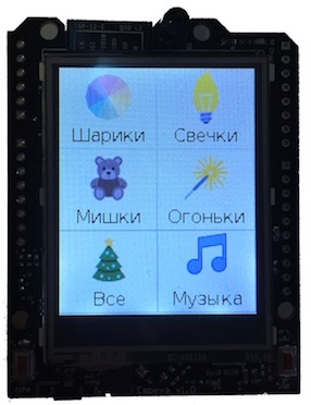
In the last article I wrote about the "smart" extension for the new Christmas tree. The sketch GUI consists of two screens.
- Christmas tree screensaver
- screen with buttons on / off the garlands:

Here are some snippets from the code, as implemented by the GUI in this project:
// GHandle ghContainerMain; // GHandle ghButton1,ghButton2,ghButton3,ghButton4,ghButtonAll,ghButtonVoice,ghButtonTree; // gdispImage ballImg,bearImg,candleImg,microphoneImg,treeImg,bigTreeImg,lightsImg; // GListener glistener; // extern "C" void gwinButtonDraw_ImageText(GWidgetObject *gw, void *param); void guiCreate(void) { gfxInit(); // "" geventListenerInit(&glistener); geventAttachSource(&glistener, ginputGetKeyboard(0), 0); gwinAttachListener(&glistener); // GUI gwinSetDefaultFont(gdispOpenFont("DejaVuSans16")); gwinSetDefaultStyle(&WhiteWidgetStyle, FALSE); gwinSetDefaultColor(HTML2COLOR(0x000000)); gwinSetDefaultBgColor(HTML2COLOR(0xFFFFFF)); // , SPIFFs gdispImageOpenFile(&ballImg, "ball.bmp"); gdispImageOpenFile(&bearImg, "bear.bmp"); gdispImageOpenFile(&candleImg, "candle.bmp"); gdispImageOpenFile(µphoneImg, "music.bmp"); gdispImageOpenFile(&treeImg, "tree.bmp"); gdispImageOpenFile(&lightsImg, "lights.bmp"); gdispImageOpenFile(&bigTreeImg, "bigtree.bmp"); // GUI GWidgetInit wi; gwinWidgetClearInit(&wi); wi.gx = 0; wi.gy = 0; wi.g.width = 176; wi.g.height = 220; wi.g.show = TRUE; ghContainerMain = gwinContainerCreate(0, &wi, 0); wi.g.parent = ghContainerMain; wi.customDraw = gwinButtonDraw_ImageText; wi.customStyle = 0; wi.customParam = &bigTreeImg; wi.gx = 0; wi.gy = 0; wi.text = ""; ghButtonTree = gwinButtonCreate(0, &wi); wi.g.show = FALSE; wi.customParam = &ballImg; wi.g.width = 88; wi.g.height = 73; wi.text = ""; ghButton1 = gwinButtonCreate(0, &wi); wi.customParam = &candleImg; wi.gx = 88; wi.gy = 0; wi.text = ""; ghButton2 = gwinButtonCreate(0, &wi); wi.customParam = &bearImg; wi.gx = 0; wi.gy = 73; wi.text = ""; ghButton3 = gwinButtonCreate(0, &wi); wi.customParam = &lightsImg; wi.gx = 88; wi.gy = 73; wi.text = ""; ghButton4 = gwinButtonCreate(0, &wi); wi.customParam = &treeImg; wi.gx = 0; wi.gy = 146; wi.text = ""; ghButtonAll = gwinButtonCreate(0, &wi); wi.customParam = µphoneImg; wi.gx = 88; wi.gy = 146; wi.text = ""; ghButtonVoice = gwinButtonCreate(0, &wi); } static bool screenSaver = false; // void switchScreen (bool flag) { gwinSetVisible (ghButton1,flag); gwinSetVisible (ghButton2,flag); gwinSetVisible (ghButton3,flag); gwinSetVisible (ghButton4,flag); gwinSetVisible (ghButtonAll,flag); gwinSetVisible (ghButtonVoice,flag); gwinSetVisible (ghButtonTree,!flag); screenSaver = !flag; } static unsigned long timeLastActivity =0; void loop() { unsigned long now = millis(); // GEvent* pe = geventEventWait(&glistener, 2); if (pe && pe->type == GEVENT_GWIN_BUTTON) { GEventGWinButton *we = (GEventGWinButton *)pe; if (we->gwin == ghButton1) {/* */} if (we->gwin == ghButton2) {/* */} if (we->gwin == ghButton3) {/* */} if (we->gwin == ghButton4) {/* */} if (we->gwin == ghButtonAll) {/* */}; if (we->gwin == ghButtonVoice) {/* */}; if (we->gwin == ghButtonTree) {switchScreen (true); startRecognize();} timeLastActivity = now; } // 10 , if (!screenSaver && now - timeLastActivity > 10000) { switchScreen (false); } delay (10); } As a result - a reasonable number of lines of code gives a complete, and for my taste, beautiful GUI. On the githabe full version of the sketch
More usage examples
Simple oscillograph
Sources on githaba: the sketch itself
Tetris
Github sources: tetris
the source of the sketch from the first video
So, in this article, we managed to make a convenient and beautiful GUI solution, using the libraries available in Open Source.
')
Source: https://habr.com/ru/post/346276/
All Articles