Mobile devices from the inside. Memory markup, file structure description and markup memory
1. Introduction
As it turned out, the layout of the physical memory of mobile devices (MU) is a little-described section of knowledge needed by the developer. Since memory exists in all devices created on the basis of microprocessors or microcontrollers, and there are already billions of them, this is also a very, very demanded section of knowledge.
This article focuses on the aspects of markup memory only MU, because it is here that there exists a coil closely tied up by different manufacturers from markup description files with the almost complete absence of theoretical data on the structure of these files themselves.
The markup of the physical memory of the MU is formed on the basis of tables or lists of descriptions of parameters of the memory sections. Almost every manufacturer of the MU has its own form (structure) of these tables. Nevertheless, all descriptions of the parameters of sections have much in common, which allows considering them in a single context.
')
Based on the description tables, memory markup files are then formed, which, as partition images, are stitched directly into the MU memory.
2. What is memory markup?
In more detail, what constitutes the markup of the memory of a ME, and why it is needed, can be found, for example, in [1]. Here is another publication that explains the memory device and its markup in an accessible manner [2].
In short, the memory markup, as a process, performs the distribution of the entire volume of the internal physical memory of the ME into separate partitions, which may have different functional purposes, including different file systems, and different access rights. This allows you to allocate in memory a separate area for data storage and user work, separately for the operation of the operating system, to encrypt or format partitions if necessary and independently of each other, etc.
When performing markup, the developer MU must adhere to some rules, which are called memory markup schemes. The markup scheme describes the placement of all sections of physical memory: their order, offset and name, i.e. label or section name. Other parameters can be specified: its size, type, region, flags, etc.
To perform the markup of memory using two types of files: text and binary (binary RAW-files).
A text file is a list (list) of all sections of memory, each entry of which contains a description of the main parameters of these sections. It is used when performing several operations:
- The flasher fills the sections of the created memory markup of the MU, i.e. flashing images of sections in them;
- when automatically creating binary markup files, i.e. partition markup image.
The binary markup file contains memory markup in a structured form that is understandable for the operation of operating systems (OS). It is placed in the MU firmware and then flashed into the partition directly into the physical memory.
The process of creating a markup of memory can be described by the following algorithm:
- the sequence of allocation of sections of memory is planned;
- creates a text file describing all sections of memory, not forgetting also about the partition itself;
- On the basis of the text file data, binary files are created that represent the images of the described memory sections, including the markup section itself.
Let's look at the memory markup schemes and the structure of the parameter description tables in more detail.
3. Memory layouts
Most commonly, two memory markup schemes are used: Mbr and Gpt .
In any memory markup scheme, the first section in the user region of the ME must always be the partitioning section (Mbr, Gpt, Parameter).
3.1.Mbr Memory Markup Layout
According to the Mbr diagram, the MU memory is represented as a sequence of partitions, supplemented by a master boot record or Mbr (Master Boot Record) containing the partition description table. Mbr is physically located in the first (zero) memory sector MU:
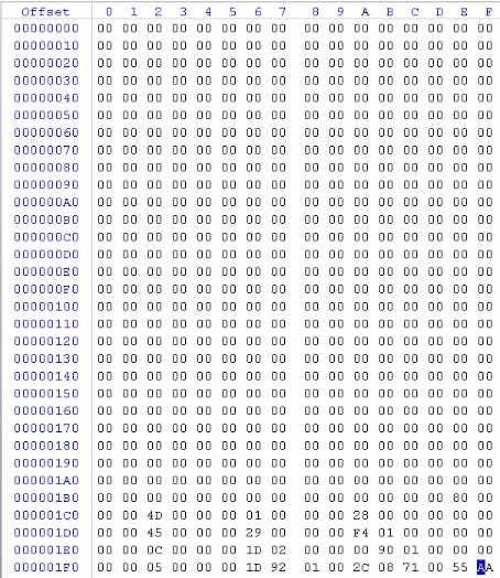
fig.1 . Master boot record
Mbr contains a signature, i.e. a sign of Mbr , and directly the partition description table itself.
The internal structure of Mbr [3] allows placing only 4 records about partitions in it, which is a significant disadvantage in modern conditions. If it is required to split the memory into more partitions, then the additional (extended) boot record Extended Boot Record ( Ebr ) is used. In this case, instead of an entry for one of the sections, an entry for an additional (extended) section containing only Ebr is placed in Mbr .
Ebr itself is designed like Mbr , and it should be used in the same way. That is, if, when filling in the Ebr table, there is again not enough space for the partition entries, then the next Ebr table is created, and so on.
Mbr and all Ebr can be placed in separate image files that are placed and stitched in the corresponding separate sections of memory. In this case, all files containing Ebr , have names numbered sequentially: Ebr1 , Ebr2 , ...
In another embodiment, Ebr is placed in one image file sequentially, then this image, respectively, is placed in one Ebr -memory partition.
3.2. Gpt-layout of memory markup
The GPT partitioning scheme (GUID Partition Table) is part of the EFI (Extensible Firmware Interface) standard, which is used instead of the BIOS for marking up the memory and loading its partitions. Switching to another format for describing partitions allowed us to eliminate the most significant drawback of the Mbr scheme — a small number of sections, since Up to 128 sections can be placed in the Gpt partition description table. The structure of the tables themselves can be found in [4].
According to the Gpt -circuit, the memory of the MU is also a sequence of sections necessary for the operation of the MU, supplemented by a front Gpt- table of the description of the sections, called the main one. In this case, after all partitions, an additional Gpt- table, called a backup, is placed. Such an arrangement of tables, theoretically, increases the reliability of the markup, since in case of failure or damage to the main Gpt-table, the OS can use a backup one to work or restore it.
4. Tables of the description of sections of memory
The descriptions of the sections of the memory MU contain information about all the sections necessary to create a markup of memory. Each row (record) of a table describes one section and contains, as a rule, the following parameters:
- - label (name or name) of the section;
- - offset section.
Since Since these tables are used by manufacturers of MUs when performing directly flashing of partition images into memory using flashers (programmers), the entries may contain additional parameters required for correct setting of partition properties, for example:
- - the name of the file containing the image of the section;
- - section size;
- - region of the section;
- - section flags, for example, “read-only”, “encrypted”, “write enabled while Fastboot is running”.
Physically, the partition description tables are text files in txt or xml format. In my practice, the following types of them were encountered:
- - parameter file . Used by manufacturers of MU based on RK chips, format - txt;
- - rawprogram0-file . Used by manufacturers of MU based on Qualcomm chips, format - xml;
- - ota-file . Universal file, used to describe the markup of the firmware by all manufacturers of MU with automatic update by "air" (OTA-update), format - txt;
- - scatter file . Used by manufacturers of MT based on MTK chips, format - txt.
Let's take a look at their structure in more detail.
4.1. Parameter file
The firmware on the RK chip contains a text file PARAMETER , which is intended to describe the construction (configuration and loading) of physical block-type memory. Moreover, it was used on LINUX OS.
The original view of the contents of the PARAMETER file for the Cube u30gt-M MU is shown below:
FIRMWARE_VER: 4.0.4Fig.2 . RK PARAMETER file
MACHINE_MODEL: U30GT-M
MACHINE_ID: 007
MANUFACTURER: RK30SDK
MAGIC: 0x5041524D
ATAG: 0x60000800
MACHINE: 3066
CHECK_MASK: 0xFF
KERNEL_IMG: 0x60408000
RECOVERY_KEY: 0.4, C, 6.0
COMBINATION_KEY: 0.4, C, 6.0
CMDLINE: console = ttyFIQ0 androidboot.console = ttyFIQ0 init = / init initrd = 0x62000000.0x008000000 mtdparts = rk29xxnand: 0x00002000 @ 0x00002000 (misc), 0x00004000 @ 0x00004000 (0x00002000), 0x00002000 (misc), 0x00004000 @ 0x00002000 (0x00002000) , 0x000C0000 @ 0x00018000 (backup), 0x00040000 @ 0x000D8000 (cache), 0x00200000 @ 0x00118000 (userdata), 0x00002000 @ 0x00318000 (kpanic), 0x00120000 @ 0x0031A000 (system), - @ 0x0043A000 (0x00318000)
4.1.1. Description of the parameters of the file PARAMETER
The PARAMETER file may contain the following parameters:
- the FIRMWARE_VER parameter indicates the version number of the firmware, for example, 4.0.4 or 1.11;
- the MACHINE_MODEL parameter specifies the NAME of the model for which the firmware is intended;
- the MACHINE_ID parameter specifies the model identifier;
- the MANUFACTURER parameter indicates the manufacturer;
- The MAGIC parameter contains the signature of the PARAMETER file, which contains a string of 4 letters: " PARM ".
- ATAG parameter. I don’t know the meaning;
- MACHINE parameter indicates the type of processor used in the MU;
- parameter CHECK_MASK . I don’t know the meaning;
- The KERNEL_IMG parameter contains the offset in bytes of the kernel image in memory during initial boot. For example, 0x6040800;
- the RECOVERY_KEY parameter and COMBINATION_KEY . I do not know their purpose;
- The CMDLINE parameter contains the command line passed to the kernel when the device is started.
Of greatest interest to the developer is the CMDLINE parameter. It contains a set of key values to configure your device.
Consider the structure of the parameter CMDLINE separately.
4.1.2. CMDLINE parameter and its capabilities
Command line format, i.e. CMDLINE , has the following form:
CMDLINE: key1 = value1 [key2 = value2], where
- key1 - key name 1;
- value1 - the value of the key 1.
Here is a list of possible keys:
- console , androidboot.console specifies the type of console device;
- init allows you to specify the process used when initializing the MU;
- initrd allows you to specify the parameters of the initrd used when booting, i.e. the offset and size of this section of memory;
- mtdparts contains a description of the markup memory;
- root allows you to assign a folder to the root user.
In turn, the mtdparts parameter has the following structure:
mtdparts = <mtddef> [; <mtddef>], where
mtddef - description of the memory markup of a block type device (CU). If the MU contains several BUs, it may contain several descriptions, which are arranged sequentially without a gap and are separated by the “semicolon” symbol.
The description of the memory markup of each control unit has the following structure:
mtddef: = <mtd-id>: <partdef> [, <partdef>], where
- mtd-id is the name of the driver (a file with the .ko extension) used to manage the data of the control unit (for example, the NAND memory driver rk29xxnand.ko);
- < partdef > is a sequence of partdef structures containing a description of the parameters of the memory partition (partition) of a given control unit and separated by a comma (",").
Each partdev entry contains a description of one memory section, a unit is taken as a unit whose size is 0x200 (512) bytes, and has the following structure:
part_size @ part_offset (label) [flag]
The parameter part_size describes the size of the section in blocks, expressed in hex number system. If instead of the size the symbol “minus” (“-”) is indicated, it means the maximum possible size, i.e. to the physical end of memory.
The part_offset parameter represents the section offset in blocks, expressed in hex number system. The offset is always aligned to the 0x1000 boundary.
The label (partition name) parameter is a string partition identifier, enclosed in parentheses, for example, (boot).
The flag parameter can take only one value - " ro ", meaning that the section is read only. The absence of a flag means that the section is readable and writable.
Some very important notes:
- the description of the markup of the memory of all CUs contained in one MU is written line by line for each CU and separated by the “semicolon” symbol;
- description of the memory markup of each CU All sections of the CU, written in one line without hyphenation and transitions to another. Section entries are separated by commas;
- sections in memory are located continuously, i.e. there are no "holes" between them.
4.2. Rawprogram0 file
The rawprogram0.xml file is intended to describe the layout of MU memory based on Qualcomm chips and has the following structure:
rawprogram0 file
Fig.3 . View of the rawprogram0.xml file from Lenovo s90a<?xml version="1.0" ?> <data> <!--NOTE: This is an ** Autogenerated file **--> <!--NOTE: Sector size is 512bytes--> <program ... filename="NON-HLOS.bin" label="modem" num_partition_sectors="131072" ... size_in_KB="65536.0" sparse="false" start_byte_hex="0x4000000" start_sector="131072" /> <program ... filename="sbl1.mbn" label="sbl1" num_partition_sectors="1024" ... size_in_KB="512.0" sparse="false" start_byte_hex="0x8000000" start_sector="262144" /> <program ... filename="sbl1.mbn" label="sbl1bak" num_partition_sectors="1024" ... size_in_KB="512.0" sparse="false" start_byte_hex="0x8080000" start_sector="263168" /> <program ... filename="emmc_appsboot.mbn" label="aboot" num_partition_sectors="4096" ... size_in_KB="2048.0" sparse="false" start_byte_hex="0x8100000" start_sector="264192" /> <program ... filename="emmc_appsboot.mbn" label="abootbak" num_partition_sectors="4096" ... size_in_KB="2048.0" sparse="false" start_byte_hex="0x8300000" start_sector="268288" /> ... <program ... filename="boot.img" label="boot" num_partition_sectors="40960" ... size_in_KB="20480.0" sparse="false" start_byte_hex="0xc00c000" start_sector="393312" /> <program ... filename="recovery.img" label="recovery" num_partition_sectors="40960" ... size_in_KB="20480.0" sparse="false" start_byte_hex="0xd40c000" start_sector="434272" /> <program ... filename="splash.img" label="splash" num_partition_sectors="40960" ... size_in_KB="20480.0" sparse="false" start_byte_hex="0xe80c000" start_sector="475232" /> ... <program ... filename="system_1.img" label="system" num_partition_sectors="262160" physical_partition_number="0" start_sector="1179648" /> <program ... filename="system_2.img" label="system" num_partition_sectors="16" physical_partition_number="0" start_sector="1442824" /> <program ... filename="system_3.img" label="system" num_partition_sectors="256992" physical_partition_number="0" start_sector="1446936" /> <program ... filename="system_4.img" label="system" num_partition_sectors="16" physical_partition_number="0" start_sector="1703936" /> <program ... filename="system_5.img" label="system" num_partition_sectors="258024" physical_partition_number="0" start_sector="1708048" /> ... <program ... filename="userdata_12.img" label="userdata" num_partition_sectors="16" physical_partition_number="0" start_sector="8302592" /> <program ... filename="userdata_13.img" label="userdata" num_partition_sectors="16" physical_partition_number="0" start_sector="8564736" /> <program ... filename="userdata_14.img" label="userdata" num_partition_sectors="16" physical_partition_number="0" start_sector="8565256" /> <program ... filename="gpt_main0.bin" label="PrimaryGPT" num_partition_sectors="34" ... size_in_KB="17.0" sparse="false" start_byte_hex="0x0" start_sector="0" /> <program ... filename="gpt_backup0.bin" label="BackupGPT" num_partition_sectors="33" ... size_in_KB="16.5" sparse="false" start_byte_hex="(512*NUM_DISK_SECTORS)-16896." start_sector="NUM_DISK_SECTORS-33." /> </data> It contains a table describing the parameters of sections in the form of xml-elements of type program . All sections are listed strictly in the order of their placement in the memory MU.
Each xml element can contain the following xml attributes:
SECTOR_SIZE_IN_BYTES - ;
file_sector_offset - , ;
filename - , ;
label - ;
num_partition_sectors - ;
physical_partition_number - ;
size_in_kb - , ;
sparse - sparse-;
start_byte_hex - , ;
start_sector - , .
4.3. Ota file
This is the only description file that describes the structure of the firmware file, and not the memory markup.
For example, the ota-update MU file on MTK chip MT6582 is as follows:
ota file
Fig.4 . Ota filePRELOADER 0x0
MBR 0x1400000
EBR1 0x1480000
PRO_INFO 0x1500000
NVRAM 0x1800000
PROTECT_F 0x1d00000
PROTECT_S 0x2700000
SECCFG 0x3100000
UBOOT 0x3120000
BOOTIMG 0x3180000
RECOVERY 0x4580000
SEC_RO 0x5980000
MISC 0x5f80000
LOGO 0x6000000
EXPDB 0x6300000
ANDROID 0x6d00000
CACHE 0x46d00000
USRDATA 0x72900000
It contains a description of those sections whose images are present in the firmware file for the ota-update, each of which has the following structure:
label part_offset,- label - the label of the section to be updated;
- part_offset - offset image of the partition in the ota-update file.
All images in the firmware are placed strictly sequentially without “holes”, so the size of each image of the part_size_n section is calculated using the following formula:
part_size_1 = part_offset_2 - part_offset_14.4. Scatter file
The scatter file contains a description of the markup of memory MU, built on the basis of MTK chips. There are three versions of the structure of this file, which is associated with the historical development of the capabilities of both the memory chips themselves and the chips of MTK processors.
4.4.1. Version 1
The markup description file of the first version contains a list of descriptions of each section of the memory, and has the following form:
scatter file version 1
Fig.5 . Scatter file of the first versionPRELOADER 0x0000000000
{
}
MBR 0x0000600000
{
}
EBR1 0x0000680000
{
}
__NODL_PMT 0x0000700000
{
}
...
ANDROID 0x0005380000
{
}
CACHE 0x002DD80000
{
}
USRDATA 0x0035B80000
{
}
FAT 0x0095B80000
{
}
__NODL_BMTPOOL 0x07FEB00000
{
}
Each section of memory is described by the following structure:
[__NODL_]name offset [length] { flag }, - __NODL_ - “No download” is a sign that the section is not being flashed and will be skipped when processed by the flasher. Accordingly, the flasher will not require an image file of this section;
- name - section label;
- offset - section offset in bytes;
- length - section length in bytes;
- flag - section flag. It may contain the entry “ro”, a sign that the section is read only.
The most commonly used abbreviated form is:
name offset { } Such a description of the memory sections assumes that:
- each section has a length before the next one, without gaps and breaks;
- between the two sections there is no third (hidden).
4.4.2. Version 2
The scatter-file of markup descriptions of memory of the second version contains the title and the table of descriptions of each section of memory itself. It has the following form:
scatter file version 2
Fig.6 . Scatter file of the second version ########################################################## # # General Setting # ########################################################## - general: MTK_PLATFORM_CFG info: - config_version: V1.1.2 platform: MT6592 project: vanzo92_wet_jb9 storage: EMMC boot_channel: MSDC_0 block_size: 0x20000 ########################################################## # # Layout Setting # ########################################################## - partition_index: SYS0 partition_name: PRELOADER file_name: preloader_vanzo92_wet_jb9.bin is_download: true type: SV5_BL_BIN linear_start_addr: 0x0 physical_start_addr: 0x0 partition_size: 0x40000 region: EMMC_BOOT_1 storage: HW_STORAGE_EMMC boundary_check: true is_reserved: false operation_type: BOOTLOADERS reserve: 0x00 - partition_index: SYS1 partition_name: MBR file_name: MBR is_download: true type: NORMAL_ROM linear_start_addr: 0x0 physical_start_addr: 0x0 partition_size: 0x80000 region: EMMC_USER storage: HW_STORAGE_EMMC boundary_check: true is_reserved: false operation_type: UPDATE reserve: 0x00 The header contains the complete firmware parameters and contains the following fields:
- config_version - version of the header. It may be V1.1.1 or V1.1.2;
- platform — hardware platform (chip type), for example, MT6582;
- project - the name of the firmware development project;
- storage - the type of memory device used, for example, EMMC;
- boot_channel - type of boot device;
- block_size - block size in bytes, for example, for EMMC this field has the value 0x20000.
Each section of memory is described by the following set of fields:
partition_index - partition label;
partition_name is the name of the partition;
file_name is the name of the file containing the image for flashing in the section, or NONE if the image is not required;
is_download is a sign of the partition load (something like __NODL_ );
type - type of section. Indicates the contents of a section. It can take the following values:
- EXT4_IMG - the partition contains part of the EXT4 file system;
- NORMAL_ROM - the section contains a saved image or a separate file;
- SV5_BL_BIN - the section contains the “raw code” (Raw Code) of the loader;
physical_start_addr - offset of the section in the memory MU (physical address), bytes;
partition_size - partition size in bytes;
region - the name of the region where the partition is located. It can take the following values:
- EMMC_BOOT_1 - the first region (region) of the loader;
- EMMC_BOOT_2 - second region of the loader;
- EMMC_USER - user region;
boundary_check - sign of the need to align the interface;
is_reserved - a sign of the need for backup;
operation_type is the type of operation. It can take the following values:
- BINREGION - the area of "raw code";
- BOOTLOADERS - bootloader;
- INVISIBLE - invisible section;
- PROTECTED - protected partition;
- RESERVED - reserved;
- UPDATE - updated section;
- reserve - the value I do not know.
When the flasher is working, it selects the parameters from the section description table, the main ones being the Begin Address and Format Length .
For MT6572-MT6577 chips, the value of the linear_start_addr field, reflecting the true offset of the section in memory (representing one continuous region), is used as the Begin Address value of the flasher; Chips do not know how to work with regions, and the memory used had only one region for partitioning. At the same time, the value of the “physical_start_addr” field is always zero.
MT6582 chips already know how to work with regions, but the memory used still has only one region. Therefore, the flasher already uses the value of the physical_start_addr field, reflecting the section offset within the regions created in memory programmatically, and the linear_start_addr field contains the offset values from the beginning of the memory chip.
Due to the fact that, starting with MT6592 chip, MTs from MTK use full-fledged work with memory regions, then for MT6592 chips and higher with a flasher, the value of the physical_start_addr field is used as the Begin Address value.
The value of the Format Length field flasher always gets from the partition_size field.
5. Files markup files.
Memory markup files contain an image of the memory markup section of the ME. Their structure depends on the markup scheme ( Gpt or Mbr ) and on the destination, for example, Pmt or Gpt backup markup files.
The following types of markup files are encountered:
- Mbr file and Ebr file. Used by all manufacturers MU using Mbr -smarking scheme memory;
- Gpt file Used by all manufacturers of MPs using Gpt- memory layout;
- Parameter file. Used by manufacturers of MU based on RK chips;
- Pmt file. Used by manufacturers of MUs based on MTK chips to create a backup memory markup file;
- pit file Used by manufacturers of Samsung based MU chips.
5.1. Mbr file
An Mbr file is an image of a memory markup partition according to an Mbr scheme, having a size of 1 sector, i.e 512 bytes
The MU uses the so-called classical structure of the Mbr file [5]:
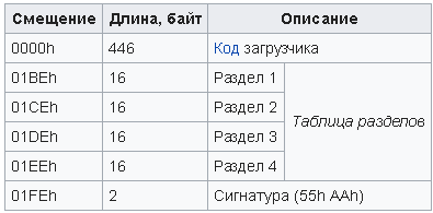
Fig.7 . The classic structure of the Mbr file
Each section parameter entry contains the following fields, the values of which differ from those adopted in the classical structure of Mbr :
============================================================== | № | | , | | | | | | | | | | / | | | hex | | |=====|===========|========|==============|====================| | 1 | IsBoot | 001 | 0x00 | | | 2 | - | 003 | 0x01 | | | 3 | Type | 001 | 0x04 | | | 4 | - | 003 | 0x05 | | | 5 | Offset | 0x04 | 0x08 | | | 6 | Size | 0x04 | 0x0 | | ============================================================== The IsBoot field has a size of 1 byte and is used to indicate the activity of the partition, the most significant bit of which indicates the boot partition:
080 - ; 000 - . The Type field has a size of 1 byte and is used by manufacturers of MUs to designate the type of section being described. The designation of the type of section may differ from manufacturer to manufacturer, but there are some common values:
================================================================ | № | | | | | / | | hex | | |=====|===========|==========|===================================| | 01 | Not | 0x00 | | | 02 | Fat12 | 0x01 | Fat12 | | 03 | Fat16 | 0x04 | Fat16 | | 04 | Extend | 0x05 | (EBR) | | 05 | Fat32 | 0x0B | Fat32 | | 06 | Fat32Lba | 0x0C | Fat32 LBA | | 07 | LinuxSwap | 0x82 | Swap Linux | | 08 | Linux | 0x83 | Linux | | 09 | LinuxEx | 0x85 | Linux | | 10 | Gpt | 0xEE | GUID (GPT) | | 11 | Bbt | 0xFF | Bad block table | ================================================================ The Offset field is 4 bytes in size and contains the value of the offset section, expressed in sectors.
The Size field is 4 bytes in size and contains the size of the partition, also expressed in sectors.
At the address 0x01FE is the signature of the Mbr file, which has the value 0xAA55.
5.2. Ebr file
The Ebr file is an image of an extended partition of memory markup, made according to the Mbr scheme. It has the same structure and size as the Mbr file:
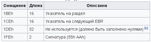
Fig.8 . The classic structure of the Ebr file
The difference lies in the fact that in an Ebr file the activity sign is always set to 0, and these files, if necessary, may already be not one, but 63. Accordingly, to place them, you also need to create up to 63 partitions, which leads to wasteful the expenditure of memory MU.
If there are relatively few memory sections, for example, as in the Star Z2 MU, then separate Ebr1 and Ebr2 files are used , which are located in separate sections. But, if there are a lot of partitions, for example, then all Ebr files can be folded into one and put the common file in one memory section.
5.3. Gpt file
A Gpt file contains a memory markup image using a Gpt scheme. Most often, MUs have a standard Gpt- scheme structure, therefore, in fact, there are two Gpt files in the firmware: the main one, called pgpt ( primary ) or gpt_main , and the secondary (backup) one, called sgpt ( secondary ) or gpt_backup .
The main Gpt- file is located in the memory of the ME, starting from the zero sector, occupies 34 sectors and has the following structure:
- the entire first sector is occupied by Mbr , called protective ( PMBR - protective master boot record);
- the entire second sector occupies the Gpt header, which is also 512 bytes in size;
- from the third to 34 inclusively (32 sectors) is occupied by the Gpt- table of the description of the sections. Each record has a size of 128 bytes, and there can be no more than 128 records in the table, so it takes 128 * 128 = 16384 bytes, i.e. 32 sectors.
The backup Gpt file occupies 33 sectors and is located in the memory of the ME, close to the end of the memory, so that the last sector of the Gpt file is located in the physically last memory sector. It has the following structure:
- The first to 32 sectors (32 sectors) is occupied by a Gpt-table of the description of the sections;
- all 33 sectors occupy the gpt header.
5.4. Parameter file
Parameter file, i.e. the image of the partition containing the markup of memory contains only the text file PARAMETER , and regardless of the size of this section. Here is how the Parameter-file looks, for example, inside the firmware for the RK U30GT-H device [6]:
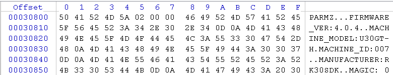
Fig.9 . Parameter file from U30GT-H on RK3066 processor
5.5. Pmt file
A pmt file is an image of the backup partition of the memory markup used by the developers of MTK company MU, and has a size of 4096 bytes.
The PMT partition image consists of two tables describing the sections of memory. At the beginning is the base, and after it is a backup or mirror (mirror) partition description table.
Each table consists of:
- - signatures of the beginning of the section description table. For a base table, this is a string of the following characters "PTv1":
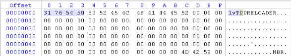
Fig.10. The signature of the base table
And for the backup table, this line has the form "MPT1":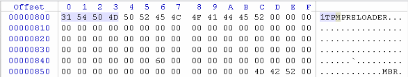
Fig.11. The signature of the backup table - - directly the table itself, containing records describing sections of memory. The end of the table is marked by an “empty” entry, i.e. a record containing the code 0x00 in all its fields;
- - end table signatures. For a base table, this is a string of the following characters "'PTv1' \ x01 \ x01 \ x03 \ x01":

Fig.12. The signature of the end of the base table
For a backup table, this line has the form "'MPT1' \ x01 \ x00 \ x03 \ x01":
Fig.13. Signature of the end of the backup table
The structure of each record has a size of 0x58 (88) bytes consists of 4 fields and has the following form:
======================================================== | № | | , | | | | / | | | hex | | |=====|===========|========|==========|==================| | 1 | Name | 040 | 0x00 | | | 2 | Size | 008 | 0x40 | | | 3 | Offset | 0x08 | 0x48 | | | 4 | mask_flag | 0x08 | 0x50 | | ======================================================== 5.6. Pit file
A Pit file ( Partition Information Table ) is an image of a partition of memory used by Samsung MU developers, and is 4096 bytes in size. Information on the structure of the image is taken from [7, 8].
A pit file consists of a header and a description table for section parameters.
The header is 28 bytes in size and contains the following fields:
====================================================== | № | | , | | | | / | | | hex | | |=====|========|========|==========|===================| | 1 | Magic | 004 | 0x00 | | | 2 | Count | 004 | 0x04 | | | 3 | Name | 018 | 0x08 | | ====================================================== Following is a table of descriptions of the parameters of the sections, consisting of records about the sections. A sign of the end of the table - an empty entry. Each entry contains the following fields:
================================================================ | № | | | | | / | | hex | | |=====|===========|==========|===================================| | 01 | binary | 0x00 | BINARY_TYPE_ | | 02 | device | 0x04 | PARTITION_DEV_TYPE_ | | 03 | id | 0x08 | | | 04 | flags | 0x0C | | | 05 | update | 0x10 | PARTITION_UPDATE_ATTR | | 06 | part_off | 0x14 | | | 07 | part_len | 0x18 | | | 08 | offset | 0x1C | - | | 09 | file_size | 0x20 | - | | 10 | label | 0x24 | | | 11 | file_name | 0x44 | - | | 11 | fota_name | 0x64 | FOTA- | ================================================================ The binary field contains the type of operating system. The following values are valid:
0 - APP ( ); 1 - MODEM ( ). The device field contains the device type. The following values are valid:
0 - unknown; 1 - file/fat; 2 - mmc; The id field contains the sequence number of the section in the firmware.
The flags field contains section flags. May take values:
000 - RO; 001 - R/W; 0x02 - STL. The update field contains section flags when updating. May take values:
0x00 - unknown; 0x01 - FOTA; 0x02 - secure; The part_off field contains the offset of a section in memory, expressed in blocks.
The part_len field contains the size of the section in memory, expressed in blocks.
The offset field contains the offset of the image file in the firmware, expressed in blocks.
The file_size field contains the size of the image file, expressed in blocks.
The label field is 32 bytes long and contains a memory section label, terminated by zero (0x00).
The file_name field contains the name of the image file of the firmware section, terminated by zero (0x00).
The fota_name field contains the name of the image file of the FOTA update firmware section, terminated by zero (0x00).
6. Used information.
1. "What is memory markup?"
2. “Introduction to disk layout”
3. “What is MBR and EBR?”
4. “What is GPT?”
5. "Master boot record"
6. “Stock firmware v1.09 (2012-11-21)”
7. File bootloader.c
8. PIT
Source: https://habr.com/ru/post/346144/
All Articles