Tachometer or speedometer: The flow of thoughts about measuring the frequency in the Arduino
Prehistory
If there is an Arduino at home, a car or a motorcycle in the garage, or even a motorcycle dog, there is a vague idea about programming in the head - there is a desire to measure the speed of movement or engine speed, to count the mileage and hours.
In this article, I want to share my experience in making such handicrafts.
// , , , . // . . A bit of physics
To measure the rotational speed, we need a wheel / shaft / circle / so forth sensor. The sensor is usually placed one. It is possible that it will trigger more than once per revolution. For example, you have a Hall sensor and 4 magnets on a wheel. Thus, to correctly calculate the frequency you need to know:
- the number of sensor activations per revolution K;
- Minimum Frequency Expected Min.
- maximum expected frequency Max.
= () / ; ( < ) = 0 ( < ) = That is, if the frequency is less than the reasonable minimum, then we believe that it is zero, if it is greater than the maximum, we ignore the readings.
The number of operations is understandable, but why else are these mines and maxes? Let's first consider the options for calculating the frequency.
With speed everything is simpler, it is enough to know the number π, the diameter of the wheel, and we already know the rotational speed.
Code pig
Since we are dealing with such gentle values as time and space, it is better to master the interrupts immediately.
const byte fqPin = 2; // ATMega32 2 3. volatile unsigned long counter = 0; // . void ISR() { // counter++; // } void setup() { Serial.begin(115200); // ISR fqPin. attachInterrupt(digitalPinToInterrupt(fqPin), ISR, RISING); } void loop() { // . noInterrupts(); unsigned long cnt = counter; interrupts(); // - . // ... Serial.println(cnt); delay(1000); } Pay attention to the volatile modifier in the counter variable. All variables that will be changed in the interrupt handler (ISR) must be volatile. This word tells the compiler that the variable may change unexpectedly and access to it cannot be optimized.
The ISR () function is called each time a unit appears on the leg of fqPin. We do not call this function, it is done by the controller itself. It does this even when the main program is in a stupor at the delay () function. Consider that ISR () serves an event that is independent of you and is given to you from above as setup () and loop (). The controller interrupts the execution of your program, performs ISR (), and returns back to the same point where it interrupted.
Note that in the loop () function, we disable any interrupts, in general, in order to read the counter variable and store it in the cnt temporary variable. Then, of course, turn it on again. So we can lose one call, of course, but on the other hand, the unsigned long variable has 32 bits, and the ATMega32 processor is 8-bit, it is unlikely that it will copy the data in one clock cycle, and during the copying process an interruption may occur and some data will change . For the same reason, we copy the value of counter locally, since the value of this variable, when used in different places of the program, may be different again because of its change in the interrupt.
The body of the ISR () function should be as short as possible; more precisely, the function itself should be performed as quickly as possible. This is important because it interrupts the execution of your code, which may be sensitive to unexpected delays. Some libraries disable interrupts to perform delay-sensitive operations, such as controlling the WS2812 LED strip.
We consider revolutions per unit of time.
The first thing that comes to mind is to take a time interval and count the number of measurements.
= ( / ) / const byte fqPin = 2; // ATMega32 2 3. const unsigned long interval = 1000000UL; // const int K = 1; unsigned long oldMks = 0; // volatile unsigned long counter = 0; // . void ISR() { // counter++; // } void setup() { Serial.begin(115200); // ISR fqPin. attachInterrupt(digitalPinToInterrupt(fqPin), ISR, RISING); } void loop() { // unsigned long mks=microseconds(); // . noInterrupts(); unsigned long cnt = counter; counter = 0; // interrupts(); // Serial.println( 1000000f * (float)cnt / (float)(mks-oldMks) / (float)K ); // 1000000 // . // mks-oldMks , interval , // , interval -- . // oldMks=mks; // . // delayMicroseconds(interval); } Like many simple solutions, this has unobvious disadvantages. To increase the accuracy of measurements, you need a rather large time interval. The principle is the same as that of quantization noise . At a turn-around time comparable to the counting time, significant changes in the rotational speed will not be noticed. The readings of such a frequency meter will differ up to two times for each count.
To improve accuracy at low speed, you can increase the number of K, as is done, for example, in automotive technology for the ABS sensor. You can increase the counting time. By doing both, we come to the second problem - overflow of the counter. Yes, overflow is easily treated by increasing the number of bits, but the ardume of the Arduino processor does not know how to count 64-bit numbers as quickly as we would like and how it does it with 16-bit ones.
The increase in the calculation time is also not very good, so we need to know the frequency right now, when you press the gas, and not after a couple of seconds. And after a couple of seconds, we get rather a certain average value. During this time, you can do a few times vrummm-vrumm.
There is another method. He is deprived of the above shortcomings, but, as usual, has its own.
We consider the interval between readings.
= 1 / ( * ) We can detect the time of one reading and another, calculate the difference. The inverse of the calculated interval is the frequency. Cool! But there are downsides.
const byte fqPin = 2; // ATMega32 2 3. const int K = 1; volatile unsigned long interval; // . void ISR() { // static unsigned long oldTime; // . unsigned long Time=microseconds(); interval=Time-OldTime(); oldTime=Time; } void setup() { Serial.begin(115200); // ISR fqPin. attachInterrupt(digitalPinToInterrupt(fqPin), ISR, RISING); } void loop() { // . noInterrupts(); unsigned long cnt = interval; interrupts(); // Serial.println( 1000000f / ( (float)K * (float)(cnt) ); // 1000000 // . // // , // -- . delay(250); } What if our wheel spins just barely and the measured interval exceeds reasonable limits? Above, I suggested counting frequencies below a reasonable minimum as zero.
A certain disadvantage of the method is quantization noise at high frequencies, when the integer interval is reduced to several binary bits.
I would also like some statistics calculations to improve the readings, but we take only the latter value.
Through trial and error, I selected the data display interval on the display at 250ms as the best. If more often, the numbers are smeared, if less - infuriates stagnation.
Combined method
You can try to combine the advantages of both methods.
= / / That is, we note the time not only between samples, but the time between data checks and divide by the number of samples during this time. It turns out the average interval between readings, the return value of which is the frequency. Let the compiler optimize the calculations.
const byte fqPin = 2; // ATMega32 2 3. const int K = 1; volatile unsigned long counter; // . volatile unsigned long mks; // . unsigned long oldTime; // . // . void ISR() { // mks=microseconds(); // counter++; // } void setup() { Serial.begin(115200); // ISR fqPin. attachInterrupt(digitalPinToInterrupt(fqPin), ISR, RISING); } void loop() { unsigned long rpm; // . noInterrupts(); unsigned long cnt = counter; counter = 0; unsigned long tmr = mks; interrupts(); // if (cnt > 0) { rpm = 1000000UL / ((tmr - oldTime) / cnt) / K; oldTime = tmr; } else { rpm = 0; } Serial.println( rpm ); delay(250); } Please note that the interval is not considered the time of the survey, as in the first example, but the time from the last sample to the previous last sample in the last survey. This significantly improves the accuracy of the calculation.
Thus, we can get quite reliable data at both low and high frequencies.
If you use cooperative multitasking , you can do the calculation, say 100ms times, and output to the display once every 250ms. A very short polling interval will reduce the sensitivity to low frequencies.
As they say in advertising, "but that's not all."
Bounce errors
To frighten you, suppose we measure the engine speed from an inductive ignition sensor. That is, roughly speaking, a piece of cable is wound on a high-voltage wire and we measure induction in it. This is a fairly common method, isn't it? What is so difficult? The main problem is modern ignition systems, they give not one impulse, but a pack right away.
Like that:
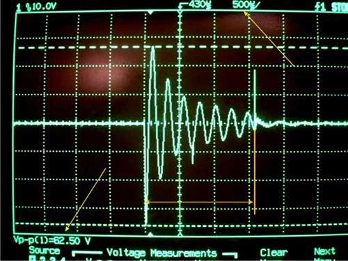
But even the usual ignition system gives transients:
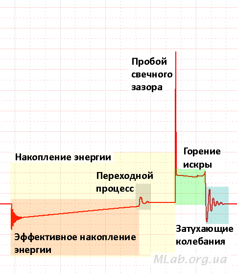
Vintage cam contact generally show great pictures.
How to deal with it? Rotation speed can not grow instantly, will not give inertia. In addition, at the beginning of the article I proposed to limit the frequency from above to a reasonable framework. Counts that occur too often can simply be ignored.
= ( 1 / ( K * ) ) const byte fqPin = 2; // ATMega32 2 3. const int K = 1; const unsigned long maxFq = 20000; // rpm ( ) const unsigned long minInterval = 1000000UL / ( K * maxFq ); // volatile unsigned long counter; // . volatile unsigned long mks; // . unsigned long oldTime; // . // . void ISR() { // static unsigned long oldTmr; // unsigned long tmr=microseconds(); if (tmr - oldTmr > minImterval) { mks=microseconds(); counter++; oldTmr=tmr; } } void setup() { Serial.begin(115200); // ISR fqPin. attachInterrupt(digitalPinToInterrupt(fqPin), ISR, RISING); } void loop() { unsigned long rpm; // . noInterrupts(); unsigned long cnt = counter; counter = 0; unsigned long tmr = mks; interrupts(); // if (cnt > 0) { rpm = K * 1000000UL / ((tmr - oldTime) / cnt); oldTime = tmr; } else { rpm = 0; } Serial.println( rpm ); delay(250); } Another type of interference is the loss of samples. Because of the same inertia, your frequency cannot change twice in one millisecond. It is clear that it depends on what you actually measure. The frequency of the beating of the wings of a mosquito can probably fall to zero within a millisecond.
Statistical processing in this case becomes quite complicated for a small interrupt handling function and I am ready to discuss options in the comments.
Features of measuring the speed of movement and speed of rotation.
When measuring the rotational speed of a gasoline engine, it is necessary to take into account the value of K, which is not at all obvious. For example, you wound a wire on a candle cable and expect that there will be one spark per revolution. It's not like that at all. Firstly, in a 4-stroke engine, a flash occurs once every two turns, in a 2-stroke engine once a revolution of the crankshaft. Secondly, to simplify the ignition system, the switch gives a spark to the currently disabled cylinders, such as on the release. To get the correct K, you need to read the engine documentation or peep the readings of the reference tachometer.
When measuring the speed of movement, the refresh rate of the display does not matter much, especially if you are drawing numbers and not moving the arrow. Even updating the information once a second will not cause rejection. With engine revs all the way around, the indicator should respond much faster to changes in revolutions.
Information output
A typical resentment of a novice developer of automotive and motorcycle electronics "arrows jerk, numbers are unreadable" is treated in a simple way - you must deceive the client. Do you think the car tachometer always shows you the truth? Of course not! Although you like this deception and you want your device to fool your head in the same way.
Arrows
If you turn on the ignition on a new fashionable car or motorcycle, the hands of the instruments will make a beautiful out to the maximum and will slowly fall to zero. Here! This is what we need to do. It is necessary that when the maximum value is shown, the arrow does not dash towards it instantly and does not fall as the scam share to zero.
So, we need to take into account the maximum speed of the arrow to increase and the maximum to decrease readings. It’s quite good to make these speeds non-linear, so that the arrow first moves faster and then slowly approaches the specified value.
Here is an example with non-linear reading:
dispRPM(unsigned int rpm) { static unsigned int lastRpm; if (rpm > lastRpm) { // unsigned int disp = rpm - (lastRpm-rpm)/5; // outputRPM(disp); // lastRpm=disp; } else { // unsigned int disp = rpm - (lastRpm-rpm)/2; // outputRPM(disp); // lastRpm=disp; } } You can play with the coefficients. The same principle is used when outputting the volume of a signal, for example, for any analog indicator: arrows, stripes, brightness, color, size, etc. The above example is the simplest, but not the most beautiful. Offer your options in the comments.
Numbers
With numbers, everything is much more complicated. Rapid changes in readings lead to the fact that several orders merge into a muddy spot. For speed, as I wrote above, you can set the interval once a second and the eye will have time to read three numbers.
In motorcycle technology, analog speed indicators are not in vain, exact figures are not needed, the relative proximity to the speed of the maximum torque, to the maximum in general and idle is important.
I propose to change the frequency of displaying information on the display depending on the degree of change in the magnitude. If the speed changes, say, by 5% from the last calculation, and not the display - you can blunt and show once in 300-500ms. If at 20%, then show once in 100ms.
You can harden the scale and show only two significant digits.
Taking into account motomatics, it is possible to fairly accurately show the idling speed as described just above and harden the output on the revolutions of two idle ones. At high speeds for racers it is more important to make blinkers like “transfer down”, “transfer up” and “you burn the engine”. That is, keep the engine near the maximum torque and prevent it from spinning above the maximum allowed speed. Blinkers are great with SmartDelay when you can inherit your class from this class with a given controller foot and blink rate, there are methods to override and they are called once at a given time.
Ideas for displaying numbers are also welcome in the comments.
Conclusion
If you step on all the rakes, you can become an experienced developer.
')
Source: https://habr.com/ru/post/346126/
All Articles