Testing the synthesizability of the beautiful features of SystemVerilog in practice
Due to the design situation, our team had to study the possibilities of the SystemVerilog language, after which no-no, but there are heated debates about which part of it is synthesized and which part is not. To put an end to speculation, I spent a little testing in practice. During the development of the test project, a number of questions were removed by delving into the literature, but one interesting point surfaced, an explicit description of which was not found. To remedy the situation, I decided to document it.
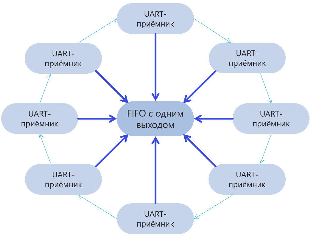
So. We have a project, the most stuffed with all sorts of SytemVerilog-ovsky things. Even if it seems that the use of this or that thing does not give much benefit - this is an erroneous impression, because the main task of the “project” is to study the possibilities of SystemVerilog. And so, we have a set of several modules (specifically, I have UART receivers), the data from which should be “merged” into a single bus, sorting them out using the RoundRobin algorithm (specifically in the case of UART, we merge the accumulated data into a single queue which on the other hand will go to the USB bus).
Here is the declaration of the UART module:
')
This is what its interface looks like, with which I plan to work using the RoundRobin algorithm:
In the merging module, the interfaces are described as an array, so that they can be indexed:
With the modules themselves, they are connected via Generate:
It would seem - beauty! Know yourself to be engaged in switching, like this (I will give an example only for the data line):
 ,
,
But that is waiting. But in reality, we get an error about the impossibility of accessing the rcvBuses object. If the index is a constant or a genvar-variable (actually, also the equivalent of a constant) - no problem, index as much as you want. For example, no one forbids doing "head on":
It will work this way, but the opportunity to change the number of receivers processed through parameterization of the module is lost. And now we are precisely checking how beautiful the solutions in the studied language can be.
Buried in the literature, I made it clear for myself that the interface is unpacked. And, unlike the structure, it cannot be declared as a wrapped entity. In the famous book SystemVerilog for Design 2nd Edition in one of the examples the solution is mentioned (but not described in detail) in passing. You need to get out of the beautiful object-oriented world into the cruel ordinary world, for which you add an array of chains:
To connect the two worlds (object and old) we add the following line:
And in the loop we do this:

The new array is packaged, so the system stops swearing at us, although, in fact, after optimization, it will be just two aliases of the same entity.
Good. What is possible, and what is not - clarified. Now it would be good to make sure with simple examples that all this disgrace will be synthesized correctly. It so happened that I now have at hand only a breadboard with a pair of buttons and a dual-channel oscilloscope. Not a lot, but that is. Let's try to come up with a task that beautifully proves the performance (or inoperability) of the indexing described above in such Spartan conditions.
There are only two buttons. That is, many sources do not imitate. But no one bothers to check everything on the reverse system. Not a lot of tires in one, and one in a lot! Two buttons - two-bit bus. We will distribute it on the FPGA legs:

One button will affect one group of legs and not affect another. When you change the state of the button, the signal will spread along the legs with a delay. The delay will be one measure between each pair. Thus, it will be possible to monitor all things of interest - both the indexing of the elements of the array and the fact that the buses switch correctly.
We make such a project:
From what I have not yet described - PLL. In one of the past articles, I came to the wrong conclusions, working on the high limits of the oscilloscope. To eliminate this, PLL reduces the frequency to one megahertz. The rest is already described. Therefore, let's go over the top of the rack:
The actual legs of the microcircuit are described as two vectors. Not very nice, but then decorate:
For now, we associate them with the array under study:
like this:
Buttons - described as a bus:
And we implement the Round Robin algorithm as follows:
We compile, enjoy how many resources it took (we have 8 legs snapped on, plus 2 bits on the counter - totally less than ten triggers could not physically turn out)

RTL Viewer also does not show anything extra. There is a PLL, there is a counter, there is a decoder, there are triggers combined into two-bit buses. Everything, as we asked:

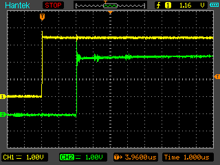
Fill in the crystal, connect to the two adjacent legs, start playing the button. We get a delay of 1 microsecond, which corresponds to a frequency of 1 MHz.
We transfer the second probe to the next leg:
And the following:
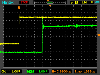
Everything corresponds to the theory. This half does not respond to the other button.
And finally, we will check what the development environment will tell us if we describe the legs not as two groups of contacts, but as a single array, which will allow us to avoid the boring generate block that connects the array with groups. Such code contains absolutely nothing superfluous, only the essence of the research (well, the PLL, transferring the results to a region that is clearly visible on the oscilloscope)
Go to Pin Planner and remember the joke about a mixed feeling:
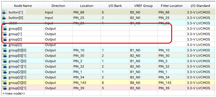
On the one hand, there is some strange group (I circled it in red), which is neither to the village nor to the city. But on the other hand, nothing is assigned to it. And our multidimensional group is also available. And it can assign legs. And the oscilloscope shows that everything is working correctly.
By the way, the picture RTL View has become just beautiful! Though in the textbook on circuitry insert!

Conclusion
The wonderful features provided by SystemVerilog are perfectly synthesized in the Quartus II development environment (I specifically downloaded the most recent version, since the language is young, and in older versions of Quartus everything may not be so rosy). Unfortunately, the language has some inconveniences due to which programming exclusively in the object-oriented world is impossible. But these are features of the language. They are solved by creating ordinary entities, which add clutter to the text, but do not affect the complexity of the resulting code, since they are just pseudonyms of object entities.
The questions about which we argued on this topic in our company are closed. Perhaps something of the above will be interesting and the rest.
So. We have a project, the most stuffed with all sorts of SytemVerilog-ovsky things. Even if it seems that the use of this or that thing does not give much benefit - this is an erroneous impression, because the main task of the “project” is to study the possibilities of SystemVerilog. And so, we have a set of several modules (specifically, I have UART receivers), the data from which should be “merged” into a single bus, sorting them out using the RoundRobin algorithm (specifically in the case of UART, we merge the accumulated data into a single queue which on the other hand will go to the USB bus).
Here is the declaration of the UART module:
module UARTreceiver( RxBus.Slave Bus, input logic [15:0] divider, input logic RxD ); ')
This is what its interface looks like, with which I plan to work using the RoundRobin algorithm:
// FIFO interface RxFifoBus #(parameter width=8)(input clk); logic [width-1:0] data; logic rdReq; logic empty; modport slave (input clk, rdReq, output data,empty); modport master (input clk, data, empty, output rdReq); endinterface In the merging module, the interfaces are described as an array, so that they can be indexed:
RxBus rcvBuses [0:UARTS](.clk (Bus.clk),.reset_n); With the modules themselves, they are connected via Generate:
genvar i; generate for (i=0;i<UARTS;i++) begin : RxGen UARTreceiver rec ( .Bus(rcvBuses[i]), .divider (16'd3125), .RxD (RxDs[i]) ); end endgenerate It would seem - beauty! Know yourself to be engaged in switching, like this (I will give an example only for the data line):
,Text
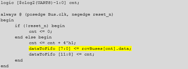
logic [$clog2(UARTS)-1:0] cnt; always @ (posedge Bus.clk, negedge reset_n) begin if (!reset_n) begin cnt <= 0; end else begin cnt <= cnt + 4'h1; dataToFifo [7:0] <= rcvBuses[cnt].data; dataToFifo [11:8] <= cnt; end end But that is waiting. But in reality, we get an error about the impossibility of accessing the rcvBuses object. If the index is a constant or a genvar-variable (actually, also the equivalent of a constant) - no problem, index as much as you want. For example, no one forbids doing "head on":
always_comb begin case (cnt) 4'h0: dataToFifo [7:0] = rcvBuses[0].data; 4'h1: dataToFifo [7:0] = rcvBuses[1].data; 4'h2: dataToFifo [7:0] = rcvBuses[2].data; 4'h3: dataToFifo [7:0] = rcvBuses[3].data; 4'h4: dataToFifo [7:0] = rcvBuses[4].data; 4'h5: dataToFifo [7:0] = rcvBuses[5].data; 4'h6: dataToFifo [7:0] = rcvBuses[6].data; 4'h7: dataToFifo [7:0] = rcvBuses[7].data; 4'h8: dataToFifo [7:0] = rcvBuses[8].data; 4'h9: dataToFifo [7:0] = rcvBuses[9].data; 4'ha: dataToFifo [7:0] = rcvBuses[10].data; 4'hb: dataToFifo [7:0] = rcvBuses[11].data; 4'hc: dataToFifo [7:0] = rcvBuses[12].data; 4'hd: dataToFifo [7:0] = rcvBuses[13].data; 4'he: dataToFifo [7:0] = rcvBuses[14].data; 4'hf: dataToFifo [7:0] = rcvBuses[15].data; default:dataToFifo [7:0] = rcvBuses[0].data; endcase end It will work this way, but the opportunity to change the number of receivers processed through parameterization of the module is lost. And now we are precisely checking how beautiful the solutions in the studied language can be.
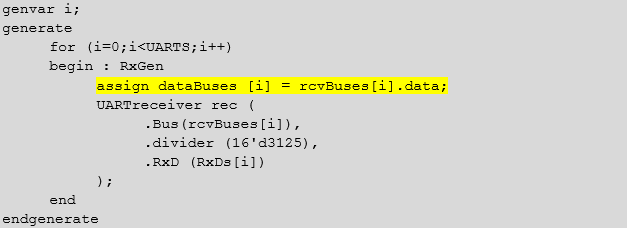
Buried in the literature, I made it clear for myself that the interface is unpacked. And, unlike the structure, it cannot be declared as a wrapped entity. In the famous book SystemVerilog for Design 2nd Edition in one of the examples the solution is mentioned (but not described in detail) in passing. You need to get out of the beautiful object-oriented world into the cruel ordinary world, for which you add an array of chains:
logic [7:0] dataBuses [0:UARTS-1]; To connect the two worlds (object and old) we add the following line:
Text
genvar i; generate for (i=0;i<UARTS;i++) begin : RxGen assign dataBuses [i] = rcvBuses[i].data; UARTreceiver rec ( .Bus(rcvBuses[i]), .divider (16'd3125), .RxD (RxDs[i]) ); end endgenerate And in the loop we do this:
Text
logic [$clog2(UARTS)-1:0] cnt; always @ (posedge Bus.clk, negedge reset_n) begin if (!reset_n) begin cnt <= 0; end else begin cnt <= cnt + 4'h1; dataToFifo [7:0] <= dataBuses[cnt]; dataToFifo [11:8] <= cnt; end end The new array is packaged, so the system stops swearing at us, although, in fact, after optimization, it will be just two aliases of the same entity.
Good. What is possible, and what is not - clarified. Now it would be good to make sure with simple examples that all this disgrace will be synthesized correctly. It so happened that I now have at hand only a breadboard with a pair of buttons and a dual-channel oscilloscope. Not a lot, but that is. Let's try to come up with a task that beautifully proves the performance (or inoperability) of the indexing described above in such Spartan conditions.
There are only two buttons. That is, many sources do not imitate. But no one bothers to check everything on the reverse system. Not a lot of tires in one, and one in a lot! Two buttons - two-bit bus. We will distribute it on the FPGA legs:
One button will affect one group of legs and not affect another. When you change the state of the button, the signal will spread along the legs with a delay. The delay will be one measure between each pair. Thus, it will be possible to monitor all things of interest - both the indexing of the elements of the array and the fact that the buses switch correctly.
We make such a project:
module ObjTest1 #(parameter cnt=4) ( input logic clk50, input logic [1:0] button, output logic [cnt-1:0] group1, output logic [cnt-1:0] group2 ); // , // 1 . logic clk; MainPll pll ( .inclk0 (clk50), .c0 (clk) ); // , // ( ) logic [1:0] wires [0:cnt-1]; // // , // genvar i; generate for (i=0;i<cnt;i++) begin : generilka assign group1 [i] = wires [i][0]; assign group2 [i] = wires [i][1]; end endgenerate // logic [$clog2(cnt)-1:0] iter; // // always_ff @(posedge clk) begin iter <= iter + 1'b1; wires [iter][0] <= button[0]; wires [iter][1] <= button[1]; end endmodule From what I have not yet described - PLL. In one of the past articles, I came to the wrong conclusions, working on the high limits of the oscilloscope. To eliminate this, PLL reduces the frequency to one megahertz. The rest is already described. Therefore, let's go over the top of the rack:
The actual legs of the microcircuit are described as two vectors. Not very nice, but then decorate:
output logic [cnt-1:0] group1, output logic [cnt-1:0] group2 For now, we associate them with the array under study:
// , // ( ) logic [1:0] wires [0:cnt-1]; like this:
// // , // genvar i; generate for (i=0;i<cnt;i++) begin : generilka assign group1 [i] = wires [i][0]; assign group2 [i] = wires [i][1]; end endgenerate Buttons - described as a bus:
input logic [1:0] button, And we implement the Round Robin algorithm as follows:
// logic [$clog2(cnt)-1:0] iter; // // always_ff @(posedge clk) begin iter <= iter + 1'b1; wires [iter] <= button; end We compile, enjoy how many resources it took (we have 8 legs snapped on, plus 2 bits on the counter - totally less than ten triggers could not physically turn out)
RTL Viewer also does not show anything extra. There is a PLL, there is a counter, there is a decoder, there are triggers combined into two-bit buses. Everything, as we asked:
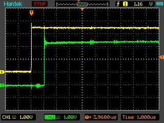
Fill in the crystal, connect to the two adjacent legs, start playing the button. We get a delay of 1 microsecond, which corresponds to a frequency of 1 MHz.
We transfer the second probe to the next leg:
And the following:
Everything corresponds to the theory. This half does not respond to the other button.
And finally, we will check what the development environment will tell us if we describe the legs not as two groups of contacts, but as a single array, which will allow us to avoid the boring generate block that connects the array with groups. Such code contains absolutely nothing superfluous, only the essence of the research (well, the PLL, transferring the results to a region that is clearly visible on the oscilloscope)
module ObjTest2 #(parameter cnt=4) ( input logic clk50, input logic [1:0] button, output logic [1:0] group [0:cnt-1] ); // , // 1 . logic clk; MainPll pll ( .inclk0 (clk50), .c0 (clk) ); // logic [$clog2(cnt)-1:0] iter; // // always_ff @(posedge clk) begin iter <= iter + 1'b1; group [iter] <= button; end endmodule Go to Pin Planner and remember the joke about a mixed feeling:
On the one hand, there is some strange group (I circled it in red), which is neither to the village nor to the city. But on the other hand, nothing is assigned to it. And our multidimensional group is also available. And it can assign legs. And the oscilloscope shows that everything is working correctly.
By the way, the picture RTL View has become just beautiful! Though in the textbook on circuitry insert!
Conclusion
The wonderful features provided by SystemVerilog are perfectly synthesized in the Quartus II development environment (I specifically downloaded the most recent version, since the language is young, and in older versions of Quartus everything may not be so rosy). Unfortunately, the language has some inconveniences due to which programming exclusively in the object-oriented world is impossible. But these are features of the language. They are solved by creating ordinary entities, which add clutter to the text, but do not affect the complexity of the resulting code, since they are just pseudonyms of object entities.
The questions about which we argued on this topic in our company are closed. Perhaps something of the above will be interesting and the rest.
Source: https://habr.com/ru/post/345638/
All Articles