Networks for the smallest. Part fourteen. Package path
Forwarding entity always for packets
Zero, one or more of the forwarding entity's own transmit interfaces
and receive packets for each packet.
Brian Petersen. Hardware Designed Network
One of the most amazing achievements of our time is how, while sitting in Norilsk, a person can chat with a friend in Thailand, at the same time buy a ticket for an evening plane to him, paying with a credit card, while somewhere in the States on his virtual machine the bot makes transactions on the exchange at the rate at which his son switches tabs when the father enters the room.
And after 10 minutes, he will order a taxi through the application on the phone, and he will not even have to take cash on the road.
At the airport, he would buy coffee, pay for hours, make a video call to his daughter in Berlin, and then launch a kintso online to pass the hour before landing.
')
During this time, thousands of MPLS tags will be hung and dropped, millions of calls to various tables will occur, base stations of cellular networks will transfer gigabytes of data, billions of packets of large and small in the form of electrons and photons with the speed of light will be sent to data centers around the world.
Is this not electric magic?
In our voyage to QoS, the theme promised many times, we will make another congress. This time we will address the life of the package in the communication equipment. Open this blue box and gut it.
Clickable and clickable.
Today:
- Briefly about the fate and the path of the package
- Planes (they are also planes): Forwarding / Data, Control, Management
- Who and how handles traffic
- Chip types: from CPU to ASICs
- Network device hardware architecture
- Life's Journey
Looking ahead, let's talk a little about the planes and introduce some definitions.
So, there are
Data Plane is the transfer of traffic from the input interfaces at the weekend - a little closer to the destination point. Data Plane is guided by the routing / switching / tagging tables (hereinafter, we will refer to them as forwarding tables ). There are places for delays - everything happens quickly.
Control Plane is a layer of protocols that monitor network status and populate transfer tables (BGP, OSPF, LDP, STP, BFD, etc.). You can slow down here - the main thing is to build the correct tables.
For what this separation was necessary, read the relevant chapter.
Since all the previous 14 parts of the SDSM were somehow about the control plane, this time we will talk about the forwarding plane.
And first of all, we introduce the concept of transit and local packages.
Transit packets are packets that are processed exclusively on the Data Plane and do not require transmission to the control plane. They fly through the node quickly and transparently.
These are mostly user (client) data, whose source and destination address is outside the device (and, most likely, the provider's network in general).
Among the transit traffic may be protocol - internal for the provider's network, but not intended for this node.
For example, BGP or Targeted LDP.
Local are divided into three different types:
- Intended for application on this device. That is, either the destination address belongs to him (configured on him). Either the destination address broadkastovy (ARP) or multicast (OSPF Hello), which the device should listen.
Here it is important to understand that we are talking about the address of the innermost transfer header: for example, for BGP or OSPF it is IP, for ISIS or STP it is MAC.
At the same time, the packet, the DIP of which is external, and DMAC - local, remains transit, because the packet must be delivered to the output interface outside, not to the Control Plane. - Generated by this device. That is, created on the CPU, on the Control Plane, and sent to the Data Plane.
- Transit packets requiring processing on the control plane. Examples include packets that have expired TTL - you need to generate ICMP TTL Expired in Transit. Or packages with IP Option installed: Router Alert or Record Route.
We in this article will talk about all. But mostly it will be about the transit - because it is for them that the provider earns money.
1. Briefly about the fate and the path of the package
By package we mean PDUs of any level — IP packets, frames, segments, and so on. It is important for us that this is a package of information.
The whole article, we will consider a modular node that forwards packets. In order not to confuse the reader, we define that it is a router .
All the arguments of this article, with amendments to the headers, protocols, and specific actions with the packet, are applicable to any network devices, be it a router, firewall, or switch — their task: to transmit the packet to the next node closer to its destination.
In order to avoid misunderstandings and inappropriate criticism: the author is aware that the real situation depends on the specific device. However, the objective of the article is to give a general understanding of the principles of operation of network equipment.
We will select the following scheme as a starting point.
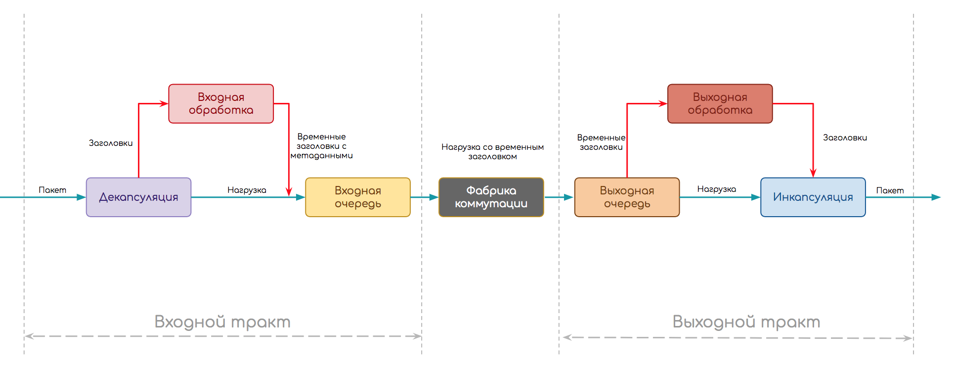
Regardless of what kind of device, how traffic processing is implemented, a package needs to go this way.
- The path is divided into two parts: the input and output paths.
- At the input, decapsulation occurs first - separation of the header from the payload and other inherent things in the protocol (for example, checksum calculation)
- Further, the stage of input processing (Ingress Processing) - the packet itself without a header (load) is buried in the buffer, and the header is analyzed. Here you can apply policies to packages, search for a destination point and an output interface, create copies, etc.
- When the analysis is completed, the header is converted to metadata (temporary header), glued to the packet and transferred to the input queue. It allows you not to send more to the output path than it can handle.
- Further, the packet can wait (or request) the explicit permission to move to the output queue, or it can simply be transferred there, and then, it seems, they will figure it out.
- There may be several output paths, so the packet then goes to the switching factory, the purpose of which is to deliver it to the correct one.
- On the output path there is also a queue - the output. In it, packets expect output processing (Egress Processing): policies, QoS, replication, shaping. Here are the future headers of the package. Also, the output queue can be useful in order to not transfer more to the interfaces than they can miss.
- And the final stage is to encapsulate the packet in the prepared headers and transfer it further.
This simplified scheme is more or less universal. Let's complicate it a bit by looking at the protocol stack. For example, an IP router must first restore the stream of bits from an electrical impulse, further recognize which type of channel protocol is used, determine the frame boundaries, remove the Ethernet header, find out what is below it (let’s IP), transfer the IP packet for further processing.
Then the scheme will look like this:
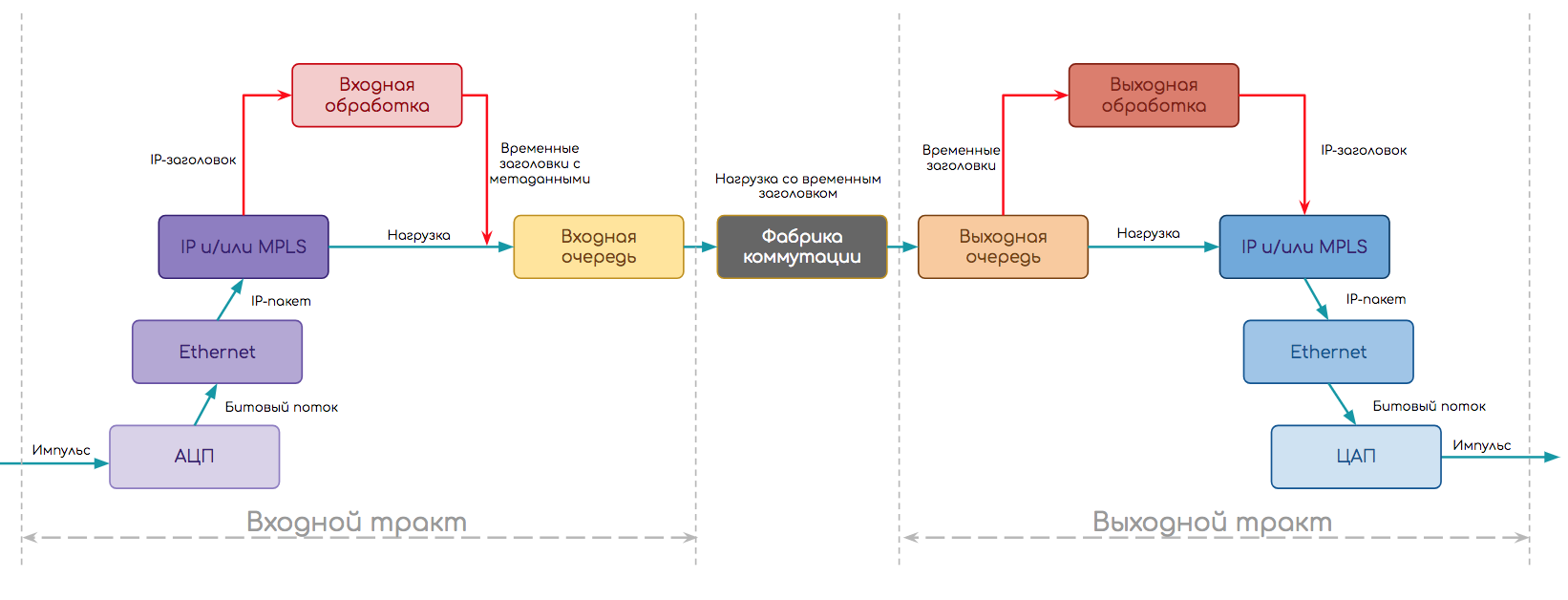
- First, the module worked the physical level .
- Using the ADC, it restored the bitstream - in a sense, physical layer decapsulation.
- Working on a specific type of port (Ethernet), he understands that the output interface will be an Ethernet module.
- Next comes decapsulation and input processing on the Ethernet module :
- IP Inbound Processing:
- Removal of headings, analysis on fields
- Policing
- Destination Address Analysis
- Search for output interface in the Forwarding Table
- Formation of temporary internal headers
- Gluing the time headers with the data and sending the packet to the output path.
- Processing in the input queue.
- Shipment through the switching factory.
- Processing in the output queue.
- On the output path, the IP module performs Output Processing:
- Policing, shaping
- Formation of the final header based on the metadata (time header) and its transfer to the Ethernet module.
- Next Output Processing on the Ethernet Module
- Search in the ARP table of the MAC address of the next node
- Ethernet header generation
- Checksum calculation
- Policing
- Descent to the physical module.
- And the physical layer module in turn breaks up the bit stream into electrical impulses and transmits it to the cable.
* The order of the operation is approximate and may depend on the implementation.
All the above steps are decomposed into hundreds of smaller ones, each of which must be implemented in hardware or software.
That's the question - in hardware or software . It pursues the world of IP-networks from the moment of their foundation and, as usual, the development occurs cyclically.
There are trivial things for which the element base exists ... mmm ... from the 60s. For example, ADC , hardware queues or CPU. And there are those who have become a breakthrough relatively recently. Some of the functions have always been and will be hardware, some will always be software, and some are torn like a monkey.
In this article, we will mostly talk about hardware devices, only making remarks about virtual ones.
2. Levels and planes

We have used these concepts so many times before that it’s time to give them definitions. There are three levels / planes in the operation of the equipment:
- Forwarding / Data Plane
- Control plane
- Management plane
Forwarding / Data Plane
Shipping Plane.
The main task of the network is to deliver traffic from one application to another. And do it as quickly as possible, both in terms of bandwidth and delays.
Accordingly, the main task of the node is to transfer the entered packet to the correct output interface as quickly as possible, having changed the headers and applying policies.
Therefore, there are pre-filled packet transfer tables — switching tables, routing tables, tags tables, neighborhood tables, and so on.
They can be implemented on special CAM, TCAM chips operating at line speed (interface). And there may be software.
Examples:
- Accept an Ethernet frame, calculate a checksum, check if there is a SMAC in the table of MAC addresses. Find the DMAC in the MAC address table, define the interface, transmit the frame.
- Accept the MPLS packet, define the input interface and the input label. Search the label table, define the output interface and the output label. Swear. Transfer to.
- Came a stream of packages. The output interface was LAG . The decision on which of the interfaces to send them is also made on the Forwarding Plane.
Difference between Data and Forwarding Plane
In the absolute majority of cases, it is considered that Data and Forwarding Plane are one and the same.
However, sometimes they are separated.
Then Data Plane means precisely the manipulation of the payload: the process of delivering a packet from the input interface to the output interface and processing it in buffers.
And Forwarding Plane is handling the headers and making the forwarding decision.
Like that:
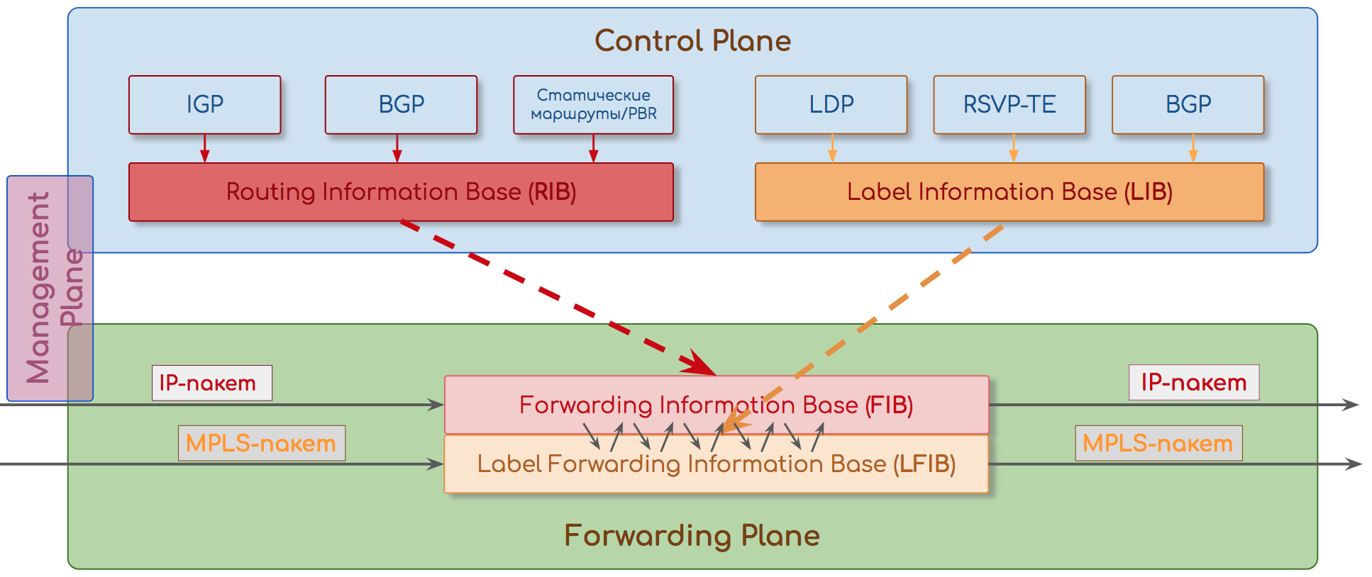
Control plane
Control plane
All over the head. It pre- fills the tables on which traffic will then be transmitted.
Protocols with complex algorithms that are expensive or impossible to perform in hardware work here.
For example, the Dijkstra algorithm can be implemented on a chip, but it is difficult. It is also difficult to make the choice of the best BGP route or the definition of FEC and the distribution of tags. In addition, for all this would have to make a separate chip or part of the chip, which practically can not be reused.
In such a situation, it is better to sacrifice subsecond convergence in favor of convenience and price.
Therefore, the software runs on a general purpose CPU.
It turns out slowly, but flexibly - all logic is programmable. And in fact, the speed on the Control Plane is not important. Once the calculated route is installed in the FIB, and then everything is not the speed of the line.
The speed of Control Plane arises with breaks, fluctuations on the network, but it is relatively successfully solved by the mechanisms of TE HSB, TE FRR, IP FRR, VPN FRR, when alternate routes are prepared in advance on the same Control Plane.
Examples:
- We launched a network with IGP. It is necessary to create Hello, agree on the parameters of the sessions, exchange databases, calculate the shortest routes, install them in the Routing Table, maintain contact through periodic Keepalive.
- BGP Update has arrived . Control Plane adds new routes to the BGP table, selects the best one, installs it in the Routing Table, and if necessary sends Update to it further.
- Admin enabled LDP . For each prefix, an FEC is created, a label is assigned, placed in the label table, and announcements are sent to all LDP neighbors.
- Collected two switches per stack. Select the main, index interfaces, update the table of shipments - the task of Control Plane.
The work and implementation of Control Plane is universal: CPU + RAM: it works the same even on rack routers, even on virtual network devices.
This system is not a thought experiment, not different functions of one program, it is really physically separated paths that interact with each other.
It all started with the separation of the planes on different boards. Then came stackable devices, where one performed intelligent operations, and the other was just an interface appendage.
Yesterday is a system like the Cisco Nexus 5000 Switch + Nexus 2000 Fabric Extender, where 2000 acts as a remote interface card for 5000.
SDN Spill 1.0 lives quietly somewhere in the parallel universe - with Openflow-like mechanisms, where Control Plane was brought to external controllers, and the transfer tables are poured into completely stupid switches.
Our reality and the near future are overlay networks configured by SDN controllers, where services are abstracted from the physical topology at a higher level of hierarchy.
And despite the fact that with each article we are more deeply immersed in the details, we learn to think freely and globally.
The division into Control and Forwarding Plane allowed to decouple the transfer of data from the work of the protocols and the construction of the network, and this resulted in a significant increase in scalability and fault tolerance.
So a single control plane module can support multiple interface modules.
In the event of a failure on the control plane, the GR, NSR , GRES and ISSU mechanisms help the transfer plane to continue to operate as if nothing had happened.
Management plane
Plane or demon of observation. It is not always allocated in a separate plane, referring its tasks to the Control Plane, and sometimes, selecting, is called Monitoring.
This module is responsible for the configuration and livelihoods of the site. It monitors parameters such as:
- Temperature
- Recycling
- Power supply
- Fan speed
- The efficiency of boards and modules.
Examples:
- Fell interface - alarm is generated, log and trap on the monitoring system
- Chip temperature rises - increases fan speed
- I found that one board stopped responding to periodic requests - it performs a restart of the boards - it suddenly rises.
- The operator connected via SSH to remove the diagonal information - the CLI is also provided with the Control Plane.
- Netconf configuration arrived - Management Plane checks and applies it. If necessary, instructs the Control Plane about the changes that have occurred and the necessary actions.
So:
Forwarding Plane - traffic transmission on the basis of transfer tables - actually, from which the operator derives profit.
Control Plane is a service level necessary to create conditions for the work of Forwarding Plane.
Management Plane - a module that monitors the overall state of the device.
Together they make up a self-contained node in a packet switching network.
The division into Control and Forwarding / Data Plane is not abstract - their functions are actually performed by different chips on the board.
So Control Plane is usually implemented on a bunch of CPU + RAM + memory card, and Forwarding Plane on ASIC, FPGA, CAM, TCAM.
But in the world of virtualization of network functions, everything is mixed up - I will make this remark until the end of the article.
3. History of traffic processing
Now with Forwarding Plane, everything is fine: 10 Gb / s, 100 Gb / s - not difficult - pay and use. Any policies without affecting performance. But it was not always so.
What is the difficulty?
First of all, it is a question of organizing the paths described above: what to do with an electrical impulse from one cable and how to transfer it to another is correct.
To do this, the network devices have a bunch of different chips.
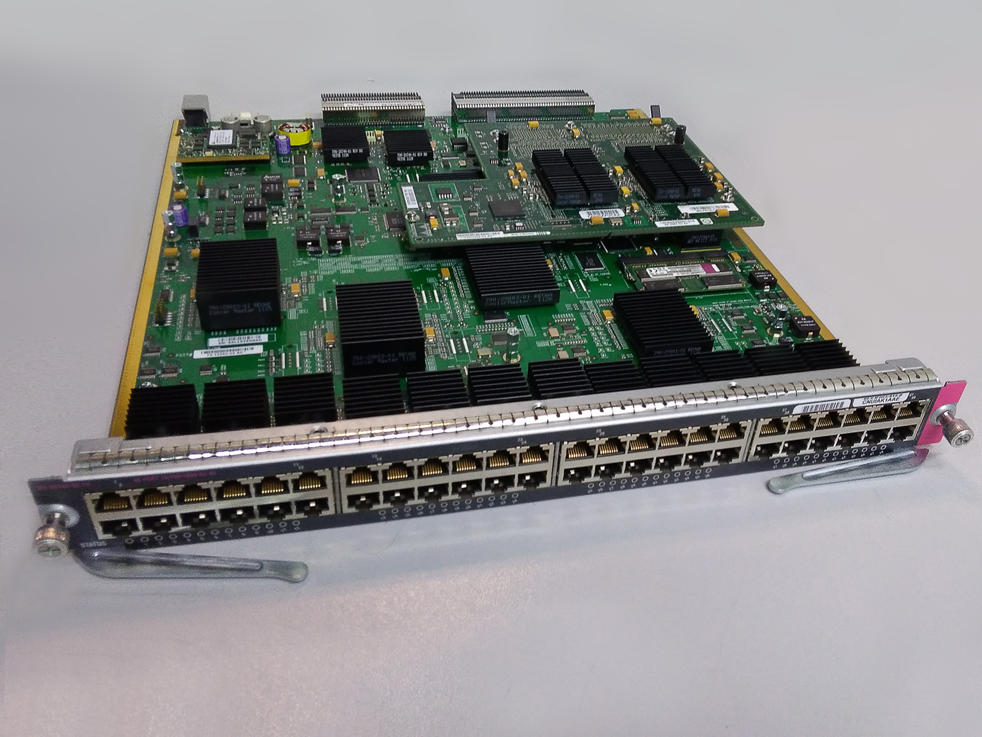
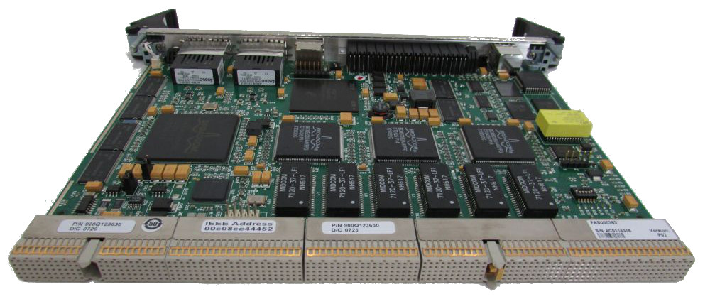
This is an example of a Cisco interface card.
For example, microcircuits (ASIC, FPGA) perform simple operations, such as ADC / DAC , checksum counting, packet buffering.
You also need a module that can parse, analyze and form packet headers.
And a module that will determine where, in which interface, the packet should be transferred. It is necessary to do this for every package of God.
Someone should also monitor whether the packet can be passed at all. That is, check it for falling under the ACL, control the flow rate and discard if it is exceeded.
Here you can also include more complex functions of address translation, firewall, balancing, etc.
Historically, all complex actions were performed on the CPU. The search for a suitable route in the routing table was implemented as a program code, and a check for compliance with policies was also implemented. The processor coped with it, but only he coped with it.
What makes this clear is clear: the performance will fall the stronger, the more traffic the device must grind and the more functions we will hang on it. Therefore, one after another, most of the functions were delegated to individual chips.
And from the usual x86-server routers have become specialized network boxes stuffed with incomprehensible details and interfaces. And Ethernet hubs are reborn as intelligent switches.
ASIC, FPGA, Network Processor took on the functions of parsing the headers and analyzing them, as well as searching for the output interface.
Queuing, QoS provisioning, congestion management are also specialized ASICs.
Things like a stateful firewall stayed on the CPU, because the number of sessions is inedible.
Another question: we have to store switching tables somewhere. Something fast.
The first thing that comes to mind is a classic RAM.
The problem with it is that the address to it goes to the address of the cell, and it already returns its contents (or content, not in Russian if).
However, the incoming packet does not carry the address of the memory cell, but only MAC, IP, MPLS.
Then we would have to have a certain hash algorithm, which, using the CPU, would calculate the cell address and extract the necessary data from there.
The only port bandwidth of 10 Gb / s means that the CPU should transmit 1 bit every 10 ns. And it has about 80 µs to transmit a packet of one kilobyte in size.
However, hash calculation is very simple algorithm, and any self-respecting ASIC will cope with this. The engineers were asked the question - what next to do with the hash?
This is how CAM - Content Addressable Memory appeared . Its addresses are hashes of values. In its cell, the CAM contains either a response value (port number, for example) or, more often, a cell address in normal RAM.
That is, the Ethernet frame came, ASICs were torn to the headers, DMAC was pulled out - they drove it through the CAM and received the desired outgoing interface.
Read more about CAM further.
What's wrong with you IP?
I knowingly took the example of an Ethernet frame. IP is another story.
MAC switching is simple: neither you aggregate routes, nor you Longest Prefix Match - only 48 unique bits.
But in IP it's all there. We may have several routes in the Routing Table with different mask lengths and choose the longest one. This is the basic principle of IP routing, with which you can not argue and do not get around.
In addition, there are complex ACLs with their wildcard masks.
For a long time there was no solution to this problem. At the dawn of packet-switched networks, IP packets were processed on the CPU. And the main problem of this is not even switching at the line speed (although it too), but the effect of additional settings on performance. Even now you can see it on some home microtic, if you configure a dozen ACLs on it - you will immediately notice how the bandwidth will drop.
The Internet grew, the politician grew bigger, and the bandwidth requirements jumped up and down, and the CPU became a stumbling block. Especially considering that sometimes it was necessary to do a search for a route not once, but to recursively plunge deeper and deeper.
So in the dashing 90s MPLS was born. What a brilliant idea - to build in advance the path to the Control Plane. Addressing in MPLS will be a label of a fixed length, and accordingly a single entry in the table of labels is needed, what to do with the package. At the same time, we do not lose the flexibility of IP, because it is the basis, and we can use CAM. Plus the MPLS header is short (4 bytes versus 20 in IP) and extremely simple.
However, ironically, at the same time, engineers have made a breakthrough by developing a TCAM - Ternary CAM. And since then there have been almost no restrictions (although not without reservations).
More from TCAM further.
As for MPLS, which in view of this event was supposed to die suddenly, barely born, he cut the door to another house. But we have already talked about this .
Oh brave new world
SDN NFV . , , , .
- .
- , .
- (Service Chain), Anti-DDoS, IDS/IPS, FW , .
. . CAM, TCAM, NP, ASIC DPDK , — SR-IOV — .
, , CAM/TCAM .
Forwarding Plane.
.
4. -
— , .
CPU — Central Processing Unit
The slowest but most flexible element of the device is the central processor.
He handles protocol packets and complex behavior.
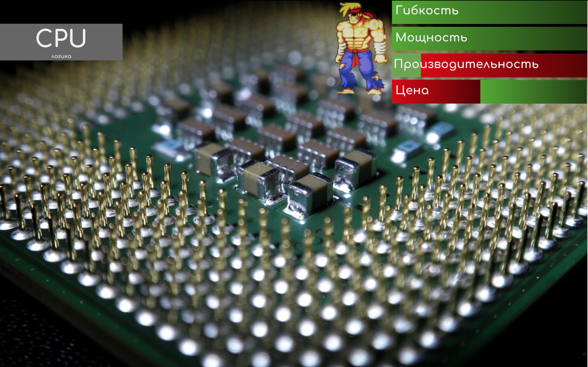
Its charm is that it is controlled by running applications and "multitasking." The logic is easy to change, just by adjusting the program code.
Things like SPF, setting a neighborhood across all protocols, generating logs, crashes, connecting to user management interfaces — all actions with complex logic — occur on it.
Actually, therefore, for example, you can observe that when the CPU is high, it becomes uncomfortable to work in the console. Although the traffic at the same time goes confidently.
The CPU assumes the functions of the Control Plane.
On devices with software forwarding, also participates in Forwarding Plane.
The CPU can be one for the whole node, or it can be separately on each board in the chassis with a distributed architecture.
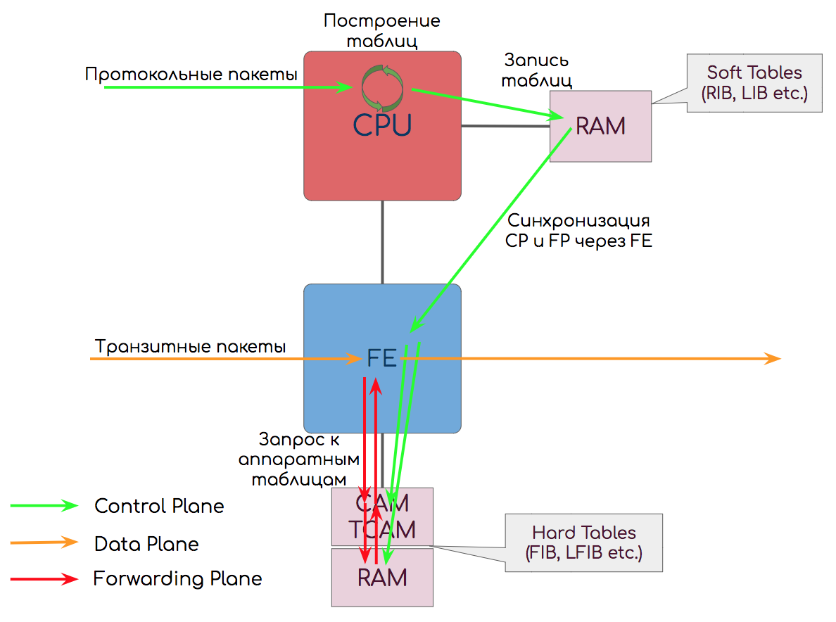
The results of their work, the CPU writes in RAM ↓.
RAM - Random Access Memory
Classic RAM - where without it?
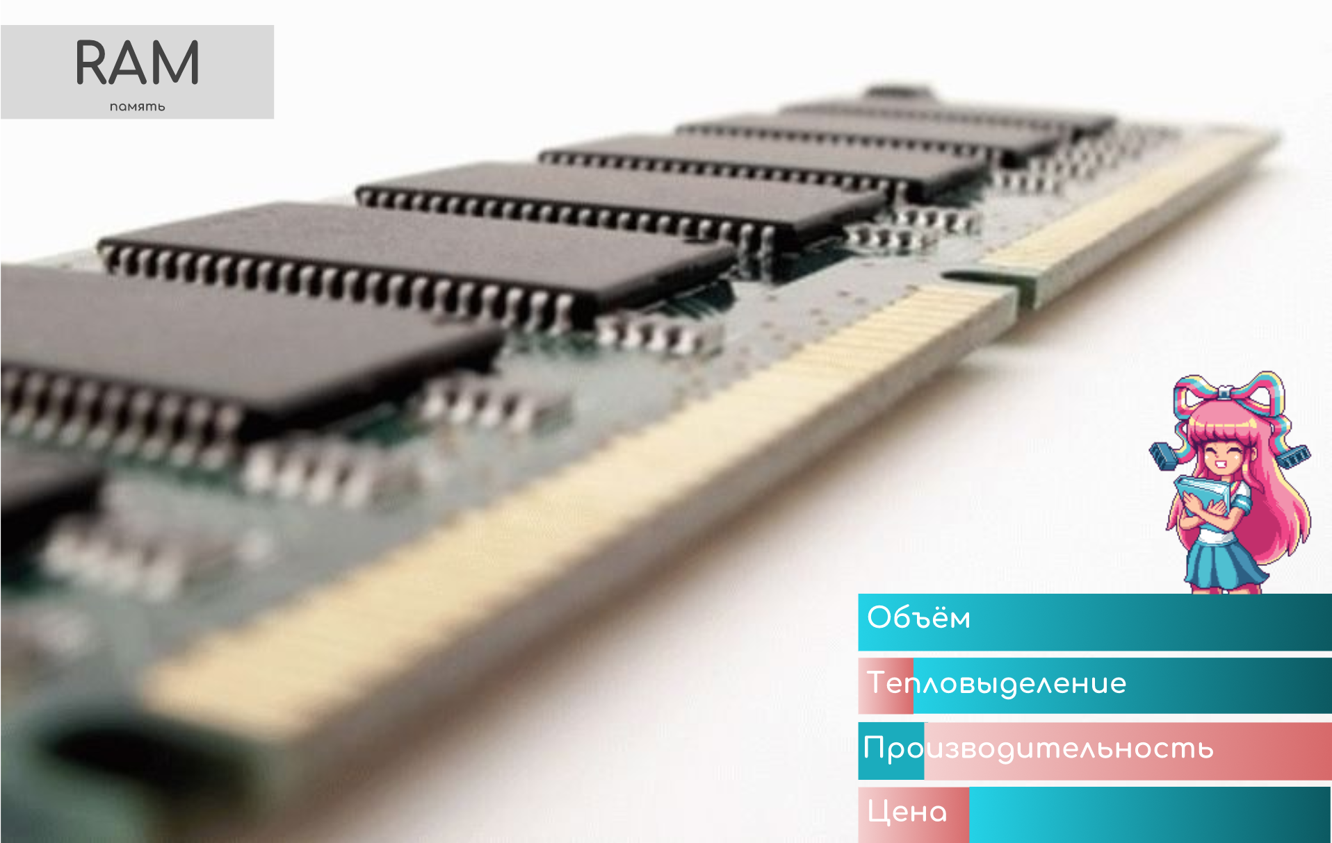
We give her the address of the cell - it is our content
It stores the so-called Soft Tables (software tables) - routing tables, labels, MAC addresses.
When you run the “show ip route” command , the request goes exactly to the RAM to the Soft Tables.
The CPU works with RAM - when he calculated the route, or built the LSP - the result is recorded in it. And from there, the changes are synchronized in the Hard Tables in CAM / TCAM ↓.
In addition, the entire contents of all tables are synchronized periodically in case suddenly for some reason the incremental changes did not come down correctly.
Soft Tables cannot be directly used for data transfer, because it is too slow - accessing the RAM goes through the CPU and requires time-consuming algorithmic search. With reservation on the NFV .
In addition, on the RAM (DRAM) chips the following queues are implemented: input, output, and interface.
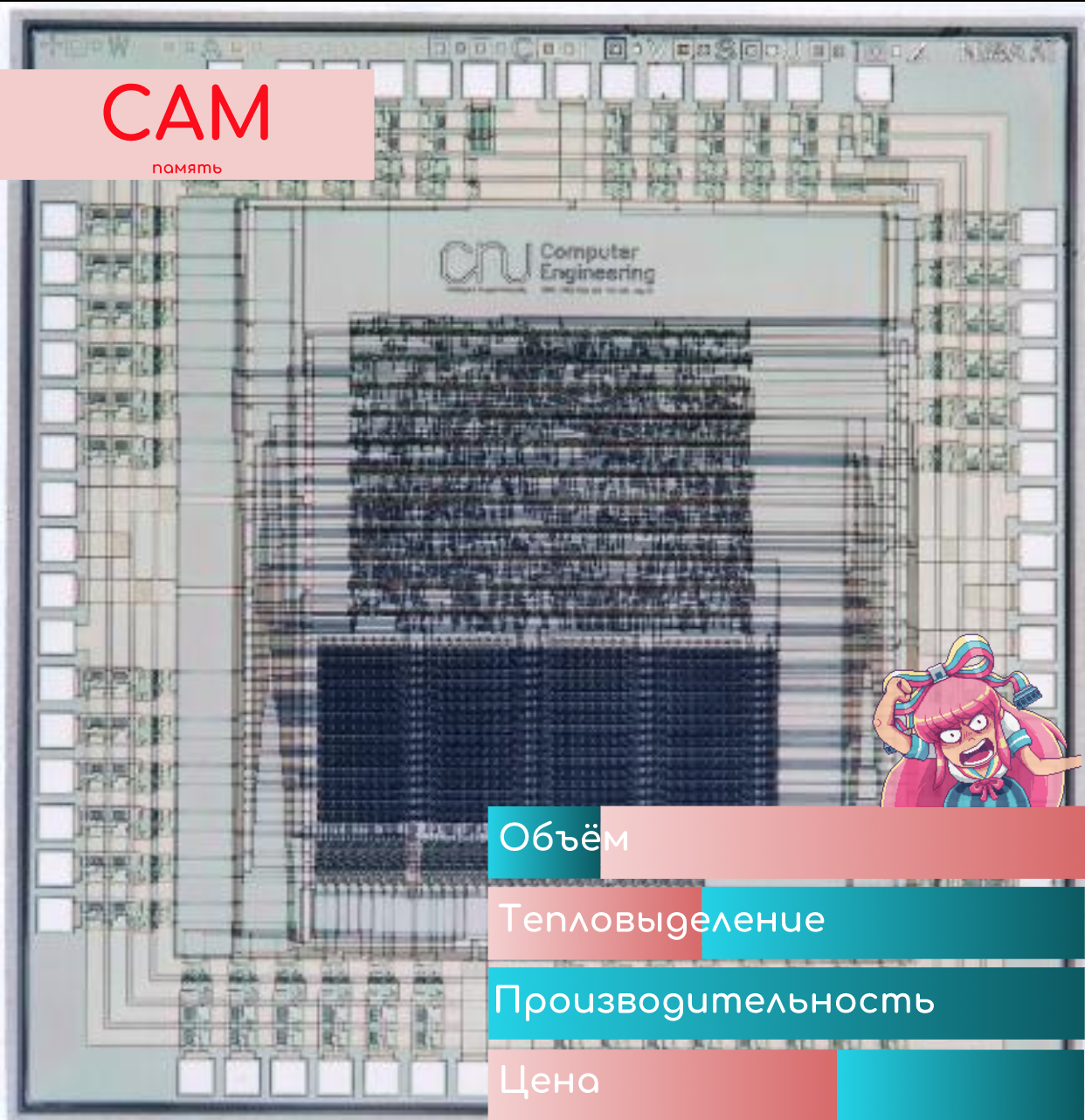
CAM - Content-Addressable Memory
This is a very clever kind of memory.
You are her value, and she you - the address of the cell.
Content-Addressable means that the addressing is based on values (content).
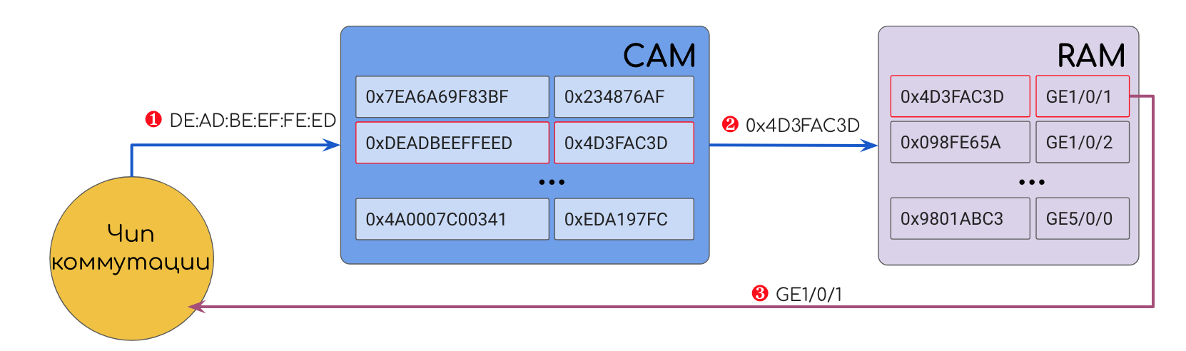
The value, for example, may be, for example, DMAC. CAM drives DMAC over all its records and finds a match. As a result, CAM will issue the cell address in classic RAM, where the output interface number is stored. Next, the device accesses this cell and sends the frame where it should be.
To achieve maximum speed, CAM and RAM are located very close to each other.
Do not confuse this RAM with the RAM containing the Soft Tables described above - these are different components located in different places.
The beauty of CAM is that it returns a result in a fixed time, independent of the number and size of entries in the table — O (1), in terms of the complexity of the algorithms.
This is achieved due to the fact that the value is compared simultaneously with all records. At the same time! Not brute force.
At the entrance of each storage cell in the CAM are comparing elements (I really like the term comparators), which can give out 0 (open) or 1 (closed), depending on what is received and what is recorded on them.
In the comparing elements recorded just the desired value.
When you need to find an entry in the table that corresponds to a particular value, this value is run simultaneously through ALL the matching elements. Literally, the electrical impulse that carries the values hits all the elements, due to the fact that they are connected in parallel. Each of them performs a very simple action, issuing for each bit 1, if the bits match, and 0, if not, that is, closing and opening the contact. Thus, the cell whose address is the desired value closes the whole circuit, the electrical signal passes and feeds it.
Here is the architecture of such a memory:
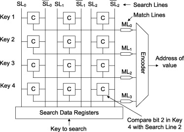
Source of the picture .
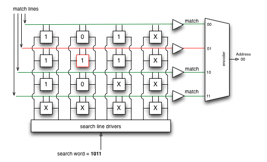
Here is an example of the work
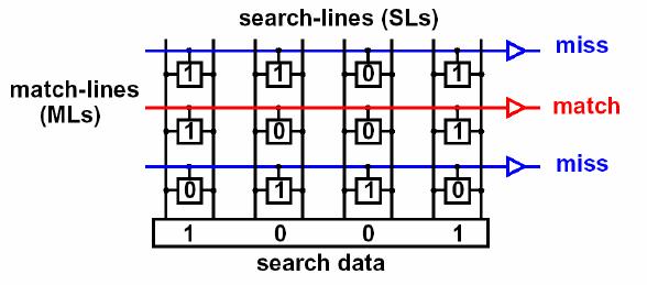
Picture from the most interesting document .
And this is the implementation scheme:
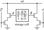
Image Source .
This is something like a key-lock pair. Only a key with the correct geometry can put the lock pins in the correct positions and rotate the cylinder.
But we have many copies of one key and many different lock configurations. And we insert them all at the same time and try to turn, and the desired value lies behind the door, the lock of which will open the key.
For flexible use of CAM, we do not take directly the values from the header fields, but calculate their hash.
The hash function is used for the following purposes:
- , . MAC- 48 16- , 2^32 , , , CAM.
- , (, — ). - — ± — . , .
, , , . Hardware Defined Networking , . - , . , , DMAC+EtherType, .
It is the hash that is encoded into the matching elements. It is the hash of the desired value that will be compared with them.
By the principle of CAM, it is similar to hash tables in programming, only implemented on chips.
MPLS switching also fits in well with this principle, which is why MPLS and IP matchmaking were in their time.
For example:
- The very first Ethernet frame arrived at the switch port.
- The switch retrieved SMAC , calculated its hash.
- He wrote down this hash in the comparing CAM elements, the interface number from which the frame came to RAM, and the cell address in the CAM cell itself in RAM.
- I sent the initial frame to all ports.
- Repeated paragraphs. 1-5 ....
- The entire table of MAC addresses is full.
- Ethernet-. , SMAC ( CAM) , , .
- DMAC , .
- CAM .
- , .
:
- CAM .
- CAM () (RAM), — .
- CAM , -. CAM , RAM.
- Verification of coincidence occurs simultaneously in all records, which is why CAM heats up, but it gives the result in constant time.
- CAM + RAM store Hard Tables (hardware tables) accessed by the switching chip.
TCAM - Ternary Content-Addressable Memory
We return to the question of what is wrong with IP.
If we take the above described CAM, then on any DIP it will very rarely be able to return 1 in all bits.
The fact is that DIP is always a single address, and the routes in the routing table are a subnet or even an aggregation of smaller routes. Therefore, there can be almost no complete coincidence - except when there is a route / 32.
Chip developers had two questions:
- How to implement it in principle?
- How to choose the best one (with the longest mask) from several suitable routes?
The answer was TCAM, in which “T” means “ternary”. ”In addition to 0 and 1 , one more X value is entered -“ not important ”(CAM is sometimes called BCAM - Binary, since there are two values - 0 and 1).
Then the search result of the desired entry in the switching table will be the contents of the cell where the longest string is 1 and the shortest is “not important”.
For example, the packet is addressed in DIP 10.10.10.10.
In the Routing Table we have the following routes:
0.0.0.0/0
10.10.10.8/29
10.10.0.0/16
10.8.0.0/13
.
Comparison elements TCAM recorded bits of the route, if the mask is 1, and "not important" if 0.
When searching for the desired entry, TCAM, like CAM, runs the search value simultaneously across all cells. The result will be a sequence of 0, 1 and “not important.”
Only those entries that returned a sequence of units, followed by "not important" are involved in the next stage of selection.
Further, from all the results, the one where the longest sequence of units is selected is how the Longest prefix match rule is implemented.
Obviously, with our watchful eyes, we immediately saw that this would be a route on 10.10.10.8/29.
Source of the picture .
Decision on the brink of genius, for which he had to pay a big price. Because of the very high density of transistors (each cell has its own set, and there must be millions of cells), they heat up no less than any CPU - you need to solve the issue of heat removal.
In addition, their production is very expensive, and it will not be sly to say that the cost of network equipment is determined before and now by the presence and volume of TCAM.
The attentive reader drew attention to the question of hash functions - after all, it transforms the original argument into something completely different from the source code, how do we compare 0, 1 and lengths? Answer: the hash function is not used here. The algorithm described above is a strong simplification of the real procedure, for details of this inquisitive reader I will send to the same book, Hardware Defined Networking .
However, memory - it is memory - only stores. She herself does not transmit traffic - someone must interact with it.
The author was unable to find generally accepted terms for the designation of certain components, therefore he took it upon himself to use his own terminological apparatus. However, he is ready at any time to listen to the recommendations and adapt the article to universal definitions.
The component that deals with packet transmission is called a switching chip - FE - Forwarding Engine . It is he who parses the headers, requests information in TCAM and redirects packets to the output interface.
Work with the package is decomposed into many small steps, each of which must be performed at the line speed, and the cumulative time to complete the path must be adequate to the requirements of the network.
An FE can be implemented on Network Processors (NP), FPGA, and Elementary ASICs or their sequences.
Here with elementary ASIC and begin.
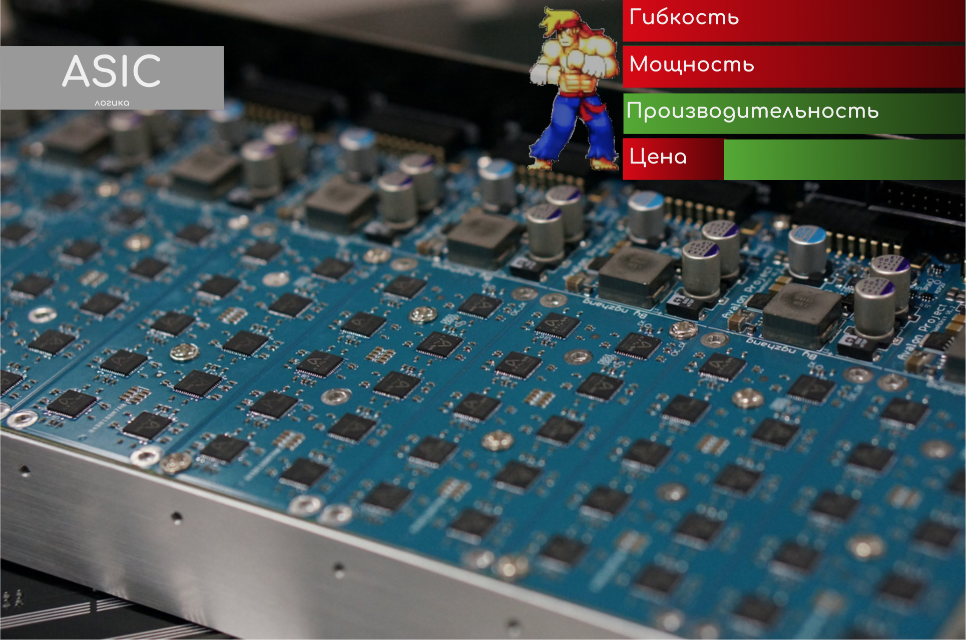
ASIC - Application Specific Integrated Circuit
As the name implies, this is a microcircuit that solves a narrow range of specific tasks. The operation algorithm is sewn into it and cannot be changed further.
Accordingly, routine operations that will never change over time fall on the ASIC.
ASIC deals with: ADC , frame checksum calculation, clock recovery from Ethernet, collection of received and sent packets statistics.
For example, we probably know where in the frame the DMAC field, its length, how to distinguish between broadcasted, multicast and unicast. These fundamental constants never change, so the functions that use them can be algorithmized by hardware, not by software.
The development and debugging process of ASIC is quite laborious, since there is no place for errors in the final chip, but when it is completed, they can be shipped by KAMAZ vehicles.
ASIC is cheap, because production is simple, massive, the probability of error is low, and the market is huge.
According to Juniper's documentation, on the part of the devices, their PFE (Packet Forwarding Engine) is based on a sequence of ASICs and does not use more complex microcircuits.
A good example of using ASICs today is cryptocurrency mining farms. Evolution has led this process from the CPU through clusters of GPUs to ASICs specialized exclusively in mining, which allowed reducing the size, power consumption and heat generation, making the process much cheaper and incredibly scalable, completely blasting away home-grown crypto-businessmen from the competitors card.
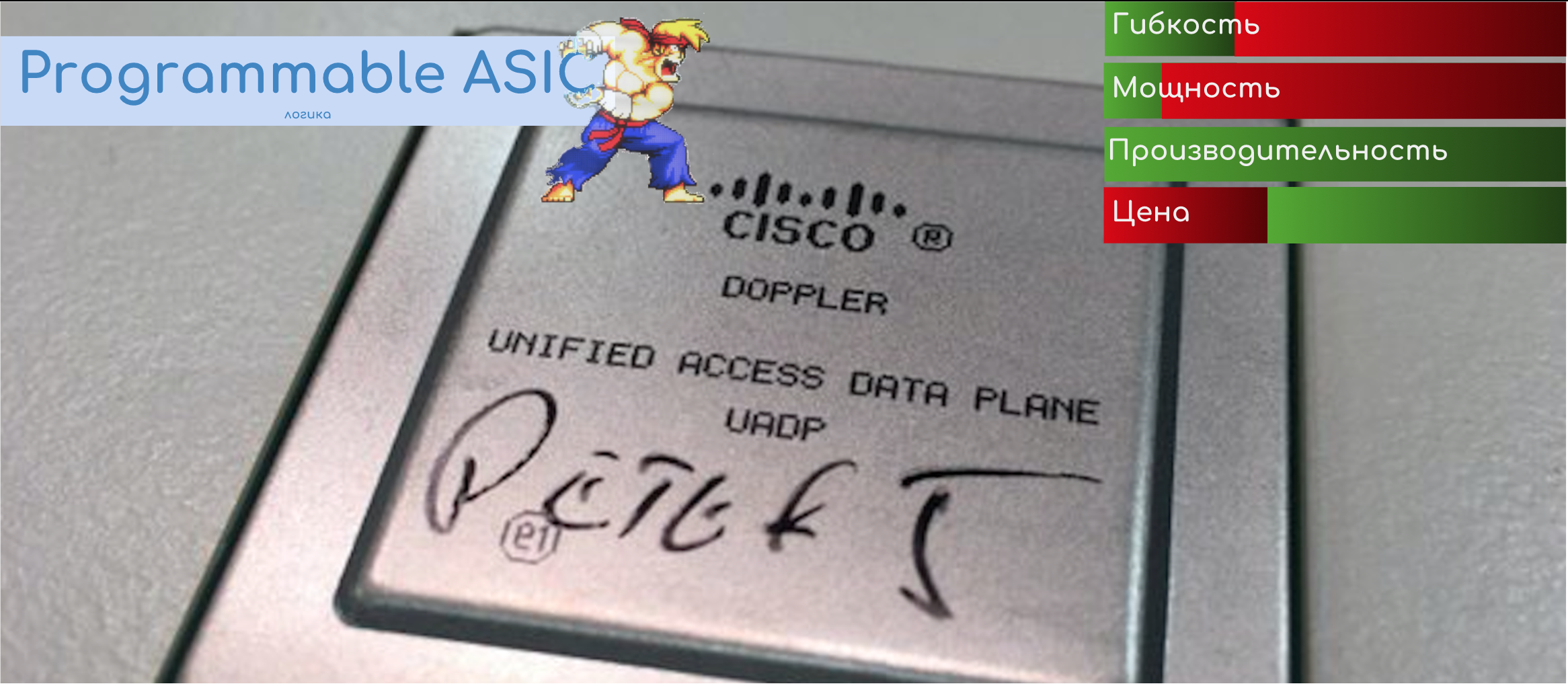
Programmable ASIC
In recent years, there has been a tendency to implement most of the functions on the ASIC. However, I want to leave the opportunity to program the behavior. Therefore, the so-called Programmable ASIC, which have low cost, high performance and some fungus.
FPGA - Field Programmable Gate Array
Not everything is up to ASICs. All that concerns the minimum intelligence and the ability to influence the behavior of the chip - this is to the FPGA.
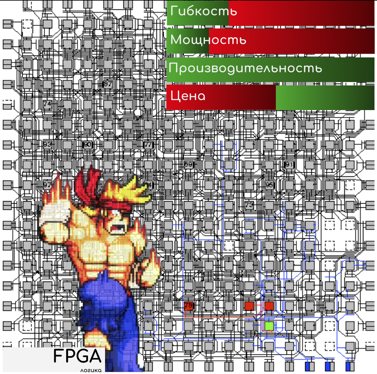
This is a programmable chip in which the firmware is poured, determining its role in the hardware.
Like ASIC, FPGA is initially aimed at solving some problem.
That is, FPGA for the packet network and for controlling the fuel supply to the engine injector are different things and you cannot turn things into one by the other.
So, we have a specialized chip with the ability to control its behavior and modernize the algorithms.
FPGA can be used for packet routing, remarking, polishing, and mirroring.
For example, from the outside, we can tell the chip to catch all the BGP and LDP packets sent to the CPU in the .pcap file.
Why is there flexibility and programming? There are many examples:
- The situation is higher, where you need to lay in it a new rule for polising, mirroring, marking
- introducing new functionality
- activation of the licensed option
- modernization of existing algorithms
- adding a new rule to analyze header fields, for example, to process a new protocol.
It turns out without developing new chips, soldering transistors, culling entire batches, just with new firmware, you can do all of the above and more.
Again, if a malfunction is detected, then you can write a patch for the software that can fix it, and at the same time update only this particular chip without affecting the rest of the system.
FPGA is significantly more expensive in design and production, mainly due to pre-built flexibility.
Due to the flexibility of the FPGA features, they are sometimes used to test a new technology, when using the firmware you can change the behavior of a component. And when the logic is run-in, it is possible to launch ASIC into production, realizing it.
NP - Network Processor
In carrier-class equipment, where the requirements for both bandwidth and protocols running on the device are quite high, specialized chips — network processors — NP are often used. In a sense, they can be considered as powerful FPGAs aimed specifically at processing and transmitting packets.
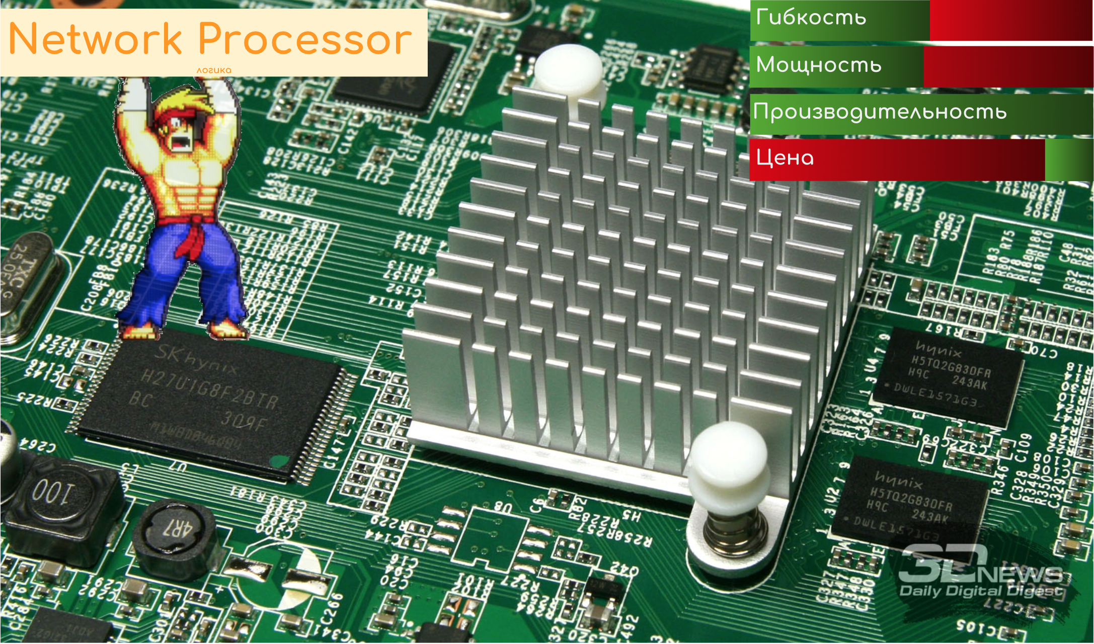
Large telecom vendors are developing their own processors (Cisco, Juniper, Huawei, Nokia), for manufacturers there are offers from several giants, like Marvell, Mellanox.
For example, a presentation of the new NP-chip Cisco 400Gb / s Full-duplex: tyts .
And this is the description of the work of the Juniper Trio chipset, which, however, is positioned as a NISP (Network Instruction Set Processor), and not NP: tyts .
A little marketing and super-effective video about Nokia FP4: tyts
Tasks and capabilities are about the same as those of the FPGA. The devil is in the details, where we will not go.
5. Hardware architecture of the switching device
Usually, even on low-cost switches, the implementation of everything and everything on a single chip is not practiced. Rather, it is a cascade of different types, each of which solves some part of the general problem.
Next we look at the reference model, how this “can” work.
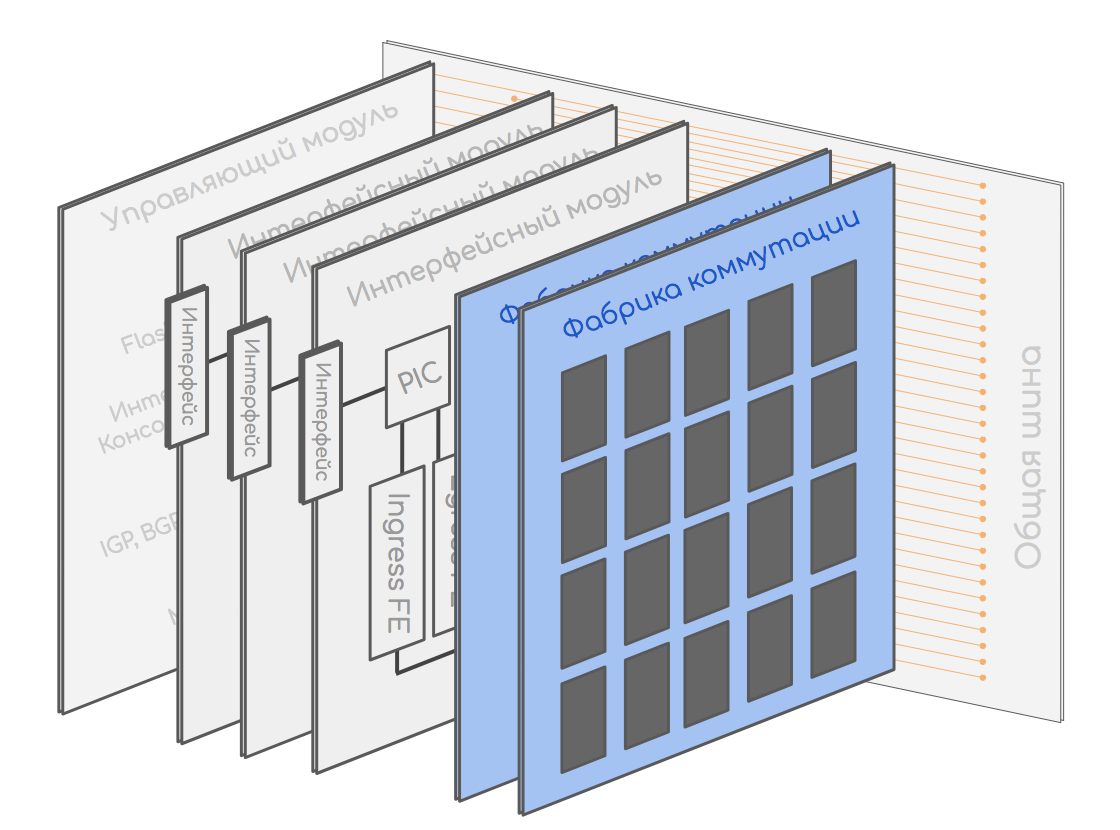
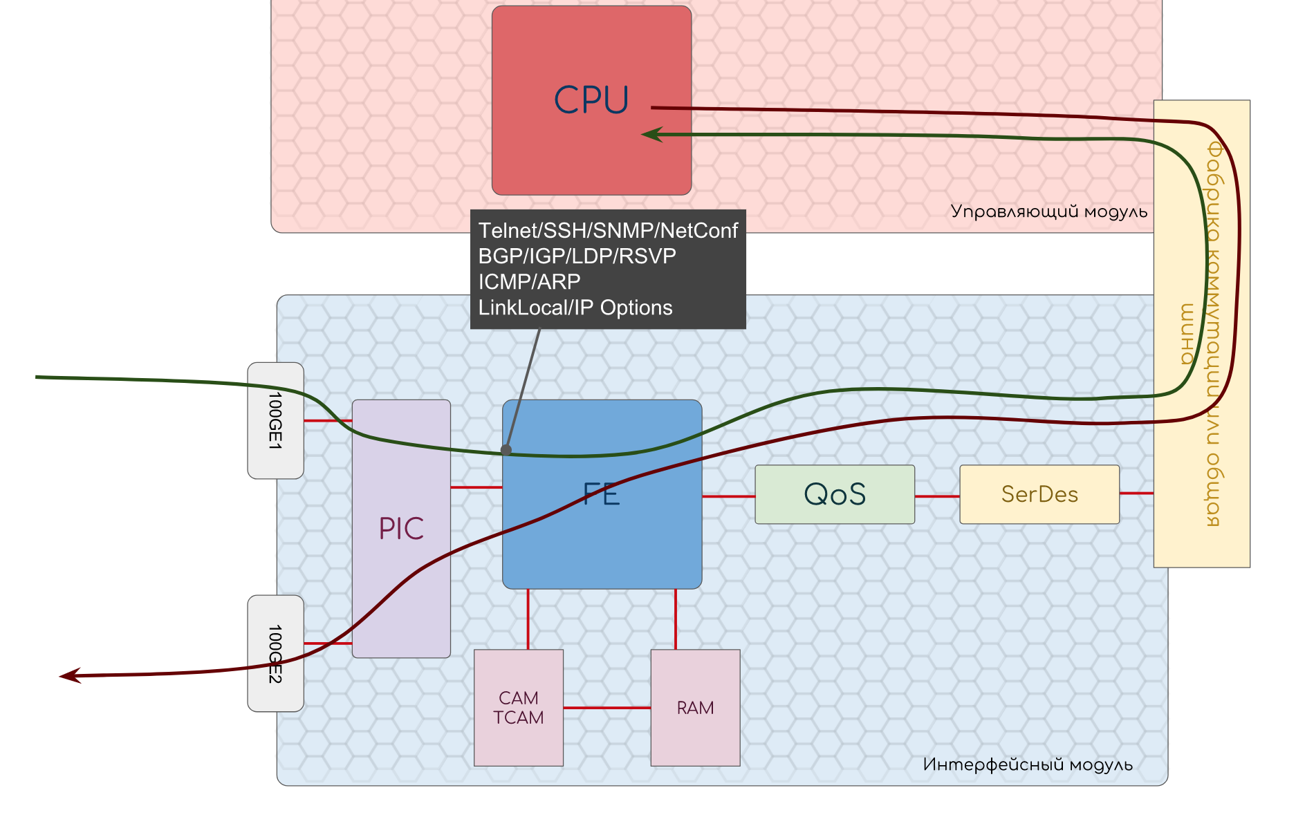
For this model, we take a modular chassis consisting of interface and control modules and a switching factory.
Like this
It will work with a standard bundle of IP, Ethernet.
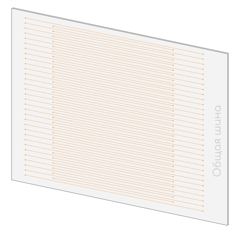
Common tire
A common bus (also known as Back Plane, also known as Midplane) of the device, connecting all modules with each other.
Usually, this is just a battery of copper contacts without any microcircuits.
Spoiler header
It looks like the back of the board, which is inserted into the bus
This is what a Juniper common bus looks like.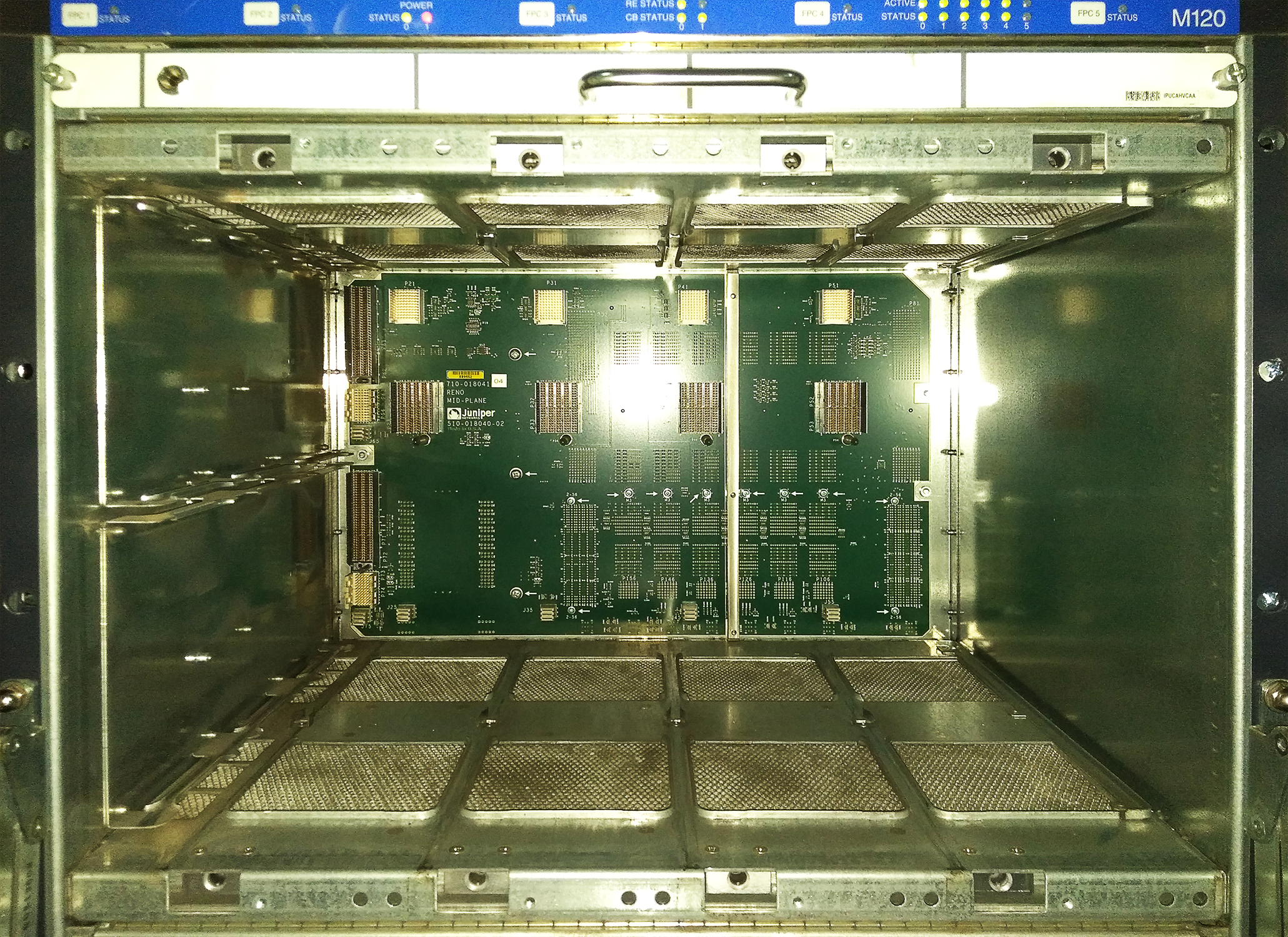
This is the general Huawei tire.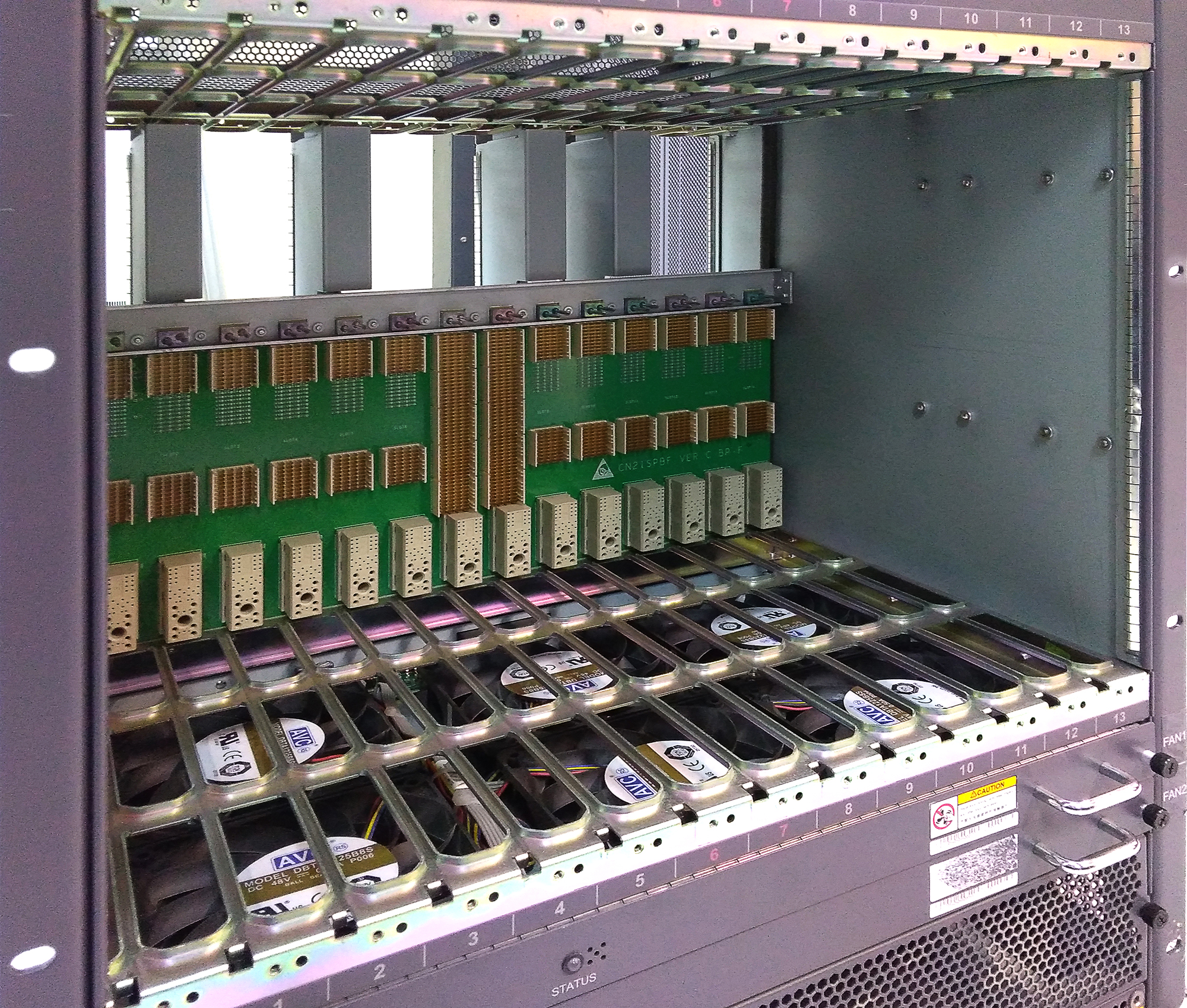
These two strips in the middle, filled with copper contacts, are slots for switching factories.
These two strips in the middle, filled with copper contacts, are slots for switching factories.
Control module

It contains the CPU, RAM, permanent memory for storing software, configuration and logs, interfaces for management.
He is responsible for the Management Plane and Control Plane.
We work with it when we connect to the device via telnet / ssh.
It loads the software into RAM and runs all other modules when power is applied.
It monitors the Heart beat of other modules - special packages, the receipt of which indicates that the module is alive and working.
He can also restart the module if the Heart beat is not received (either programmatically or turn off the power on the board).
The protocol packets are delivered to the CPU, and after processing them, it performs some action, such as: writing updates to the switching tables, generating a response packet, requesting information about any component, and so on.
The control module is engaged in the calculation of SPF, LSP, the establishment of neighbors for different protocols. It writes switching tables in the Soft Tables of RAM.
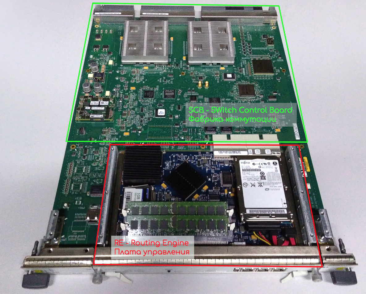
This is how control boards of different devices look like.
Cisco ASR9000 RSP (Routing and Switching). That half is closer to us. The one closest to the bus is the switching factory.

Huawei NE40E-X8 MPU

Juniper RE100
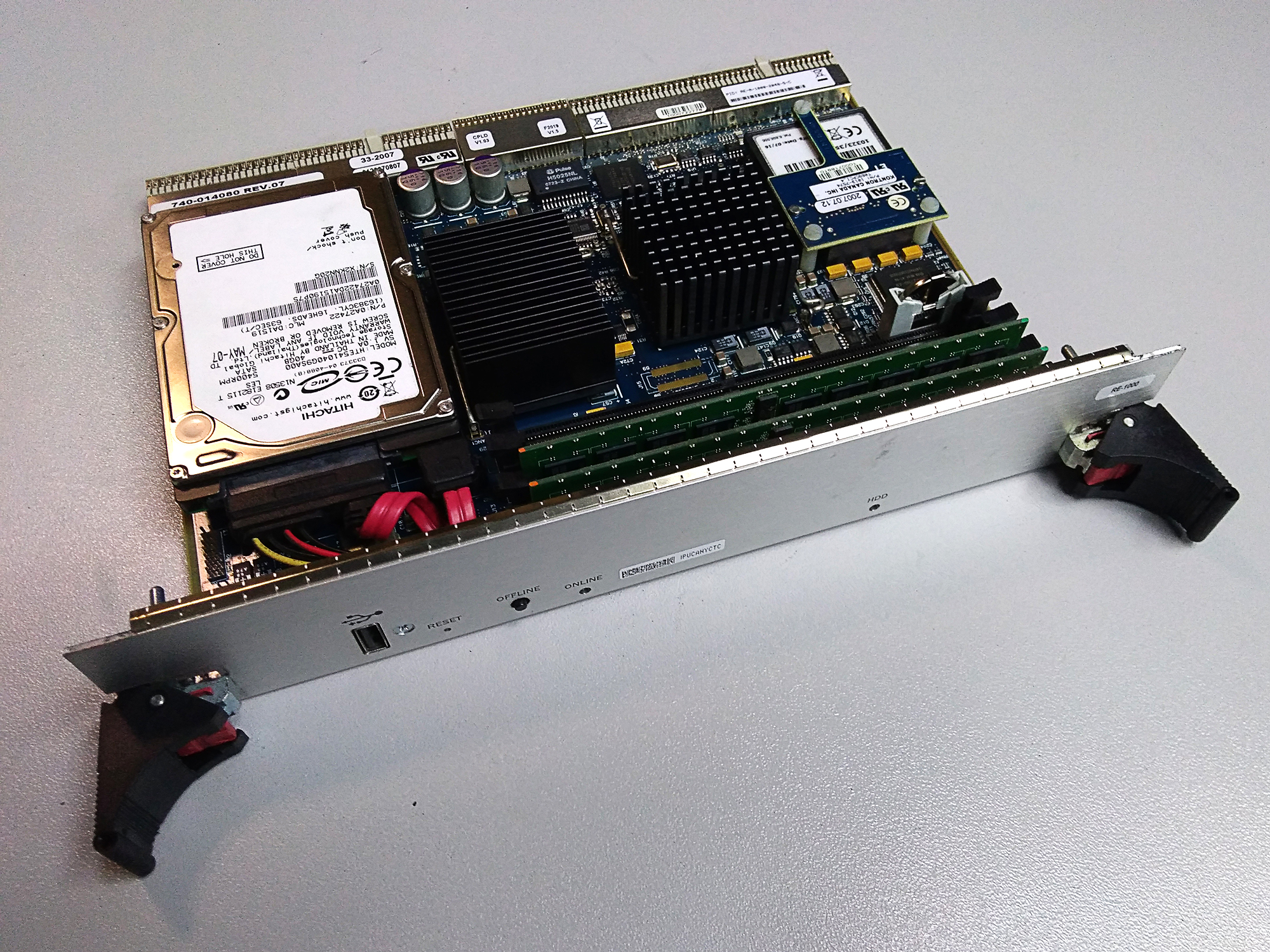
RE Juniper 1800

In all photos you can easily find the CPU, RAM and BIOS battery. Some have HDD, others have Compact Flash. Yes, you are right - this is a regular PC. Moreover, modern control boards do have performance at the computer level of 5-6 years of age.
Huawei NE40E-X8 MPU
Juniper RE100
RE Juniper 1800
In all photos you can easily find the CPU, RAM and BIOS battery. Some have HDD, others have Compact Flash. Yes, you are right - this is a regular PC. Moreover, modern control boards do have performance at the computer level of 5-6 years of age.
Interface module or line card
This is a module that carries physical interfaces and FE (switching chip) and performs the functions of Forwarding Plane.
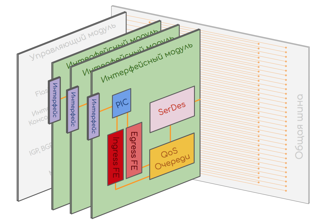
This is what Cisco's line card looks like.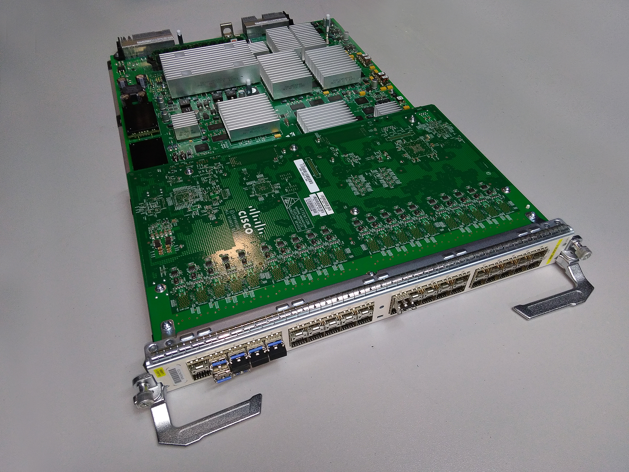
The module consists of many components that can be implemented both in a single chip (System-on-Chip) and on many individual ones depending on the class of the device and the architecture.

PIC - Physical Interface Card
The PIC contains interfaces and a chip that performs basic traffic operations:
- Recovers the bit stream from electrical pulses
- Recovers a packet from a set of bits.
- Removes overhead information (such as: preamble, IFG ).
- Calculates the checksum and
- a) if it beats with the value in the packet, skips it, removing unnecessary headers, for example FCS .
- b) if it does not beat, discards the packet and increases the counter of discarded packets with an error.
- Calculates statistics:
- number of packages
- total traffic
- peak values
- port recycling
- Unicast / Broadcast / Multicast number
- The PIC can also restore the SynchroEthernet signal, if necessary.
In case the line card is modular, the interface card will be removable and replaceable.
This is what Juniper MIC (Modular Interface Card) looks like, combined with a PIC chip.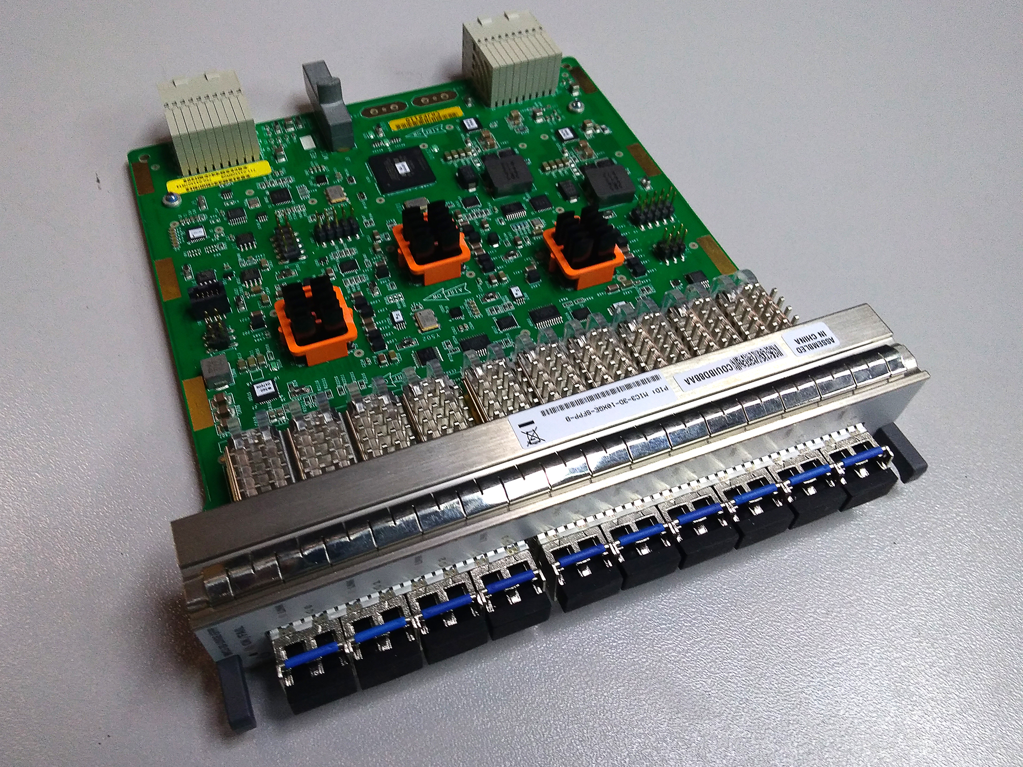
Typically, PIC chips are ASICs.
FE - Forwarding Engine
As already described above, it implements such functions as:
- Requests to CAM / TCAM
- Soft Table to Hard Table Transformation
- Decision on packet transmission (ACL, polising)
- Switching / Routing
- Priority marking
- Mirroring
- Protocol packet detection
- Signal / packet processing from the CPU.
Further ATTENTION ! This is one of the most important moments of the whole article!
First, FE is divided into Ingress FE and Egress FE . The first processes the packets on the input path, respectively, the second - on the output.
On the one hand, this division is terminological - the packet came to Ingress FE and then it should be sent to the Egress FE, possibly another board.
On the other hand, the separation is often quite physical: within the same FE chip, these two entities live: Ingress and Egress. This is logical, because the board can be both an entry point and an exit point.
Secondly, it is the input FE that determines the entire fate of the packet within the node:
- View future headlines
- Priority inside the node and when transferring outside
- Output FE and Interface
- Which of the physical members of the LAG or ECMP
* with a slight reservation that the output path can still replicate the packet or kill it because of the overflowing buffer.
Third, the FE must identify the protocol packets in transit traffic and transmit them to the CPU.
Accordingly, receiving packets (or instructions) from the CPU is also his job.
Next to the FE are the CAM, TCAM and RAM, where FE is looking for the output interface and ACL checks.
They store hard tables.
In addition, Ingress FE replicates BUM traffic — it sends one copy of the packet to each Egress FE. And Egress FE already makes as many copies, how many interfaces to send
QoS or TM - Traffic Management
Sometimes in the FE itself, sometimes as a separate chip, further comes the QoS chip, combined with the queue, usually referred to as Traffic Management.
The input queue (the queue on the input path) is needed in order not to overflow the output (the queue on the output path).
The output queue is designed to avoid a phenomenon known as Back Pressure — when packets arrive at the FE chip faster than it is able to process. This situation is impossible with Ingress FE, because it is connected to such a number of interfaces that it is able to digest the traffic from them, or Ethernet via Flow Control will take the situation under its Control.
But on Egress FE, traffic can merge from many different cards (read Ingress FE) - and it chokes on it - it's like sending two bytes.
The task of the queue is not only smoothing surges of traffic, but also manageable to drop packets when it becomes inevitable. Namely, to discard low-priority packets from the queue with a higher probability than high-priority packets. Moreover, it is desirable to monitor overloading at the interface level - because if you need to send 13 Gb / s of traffic through a 10 Gigabit interface, 3 of them will definitely be discarded, while a 400 Gbps FE will not even be close to overload.
The scheme is rather complicated - there are two queues, which means double buffering, moreover, you need to elaborate on the interfaces somehow, another question arises: what if one interface is overloaded, then the entire input queue will come up?
These difficulties were not resolved before, but today they are addressed to the VOQ mechanism - the Virtual Output Queue. VOQ is beautifully described in this post .
In a nutshell, this is the virtualization of all the queues between different FEs. There is one physical DRAM memory chip on the input path, which is internally divided into virtual queues. The number of input queues - the total number of weekends. The output queue is no longer actually located on the output module — it is only virtual in the same DRAM.
So (take the Juniper example), if there are 72 output interfaces with 8 queues on each, for a total of 576 input queues on each interface module (read TM). If there are 6 modules on the device, then it should support 3456 VOQ.
This elegantly removes the issue of double buffering and Head of Line Blocking problems, when one output queue at the moment of overload blocks all physical input - now with VOQ only the virtual one that is associated with it.

In addition, the packet is now discarded if necessary on the input queue, and it is not necessary to send it to the factory and clog the output queue.
What else is important to know about the queue, is that even those packets that are destined for another interface of the same FE must pass through the input and output queues.
This is necessary for the same struggle with Back Pressure. Only queues can protect the FE from overloads and drop excess traffic according to priorities, so there is no direct bridge for transit traffic between Ingress FE and Egress FE.
However, such “local” traffic should not be sent to the factory.
But about QoS, we'll talk more in the next part.
SerDes - Serializer, Deserializer
Another chip on the interface board is SerDes. In the case when there are several switching chips - between them you need to organize the connectivity with each and every one. Switching factories are used for this purpose and, as it turned out, it works best not with packets, but with cells of the same length. The task of SerDes is to cut packages into cells before being sent to the factory and then assemble them back - Serialize and Deserialize.
Distributed Control Plane
In the case of a distributed Control Plane architecture, the CPU and the RAM can also be located on the interface board. In this case, most of the work on the Control Plane can be performed by the local CPU, unloading the one located on the control board.
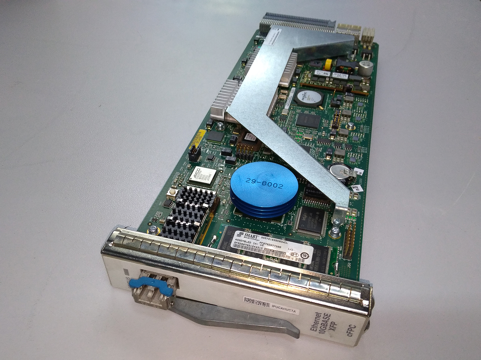
It looks like PFE on Juniper
Under the large square radiator in the center lies Forwarding ASIC (FE), under the fact that the smaller one on the left is TCAM. Under ASIC is a 512 MB RAM block of storage for Hard Tables.
The blue puck is the CPU of the distributed Control Plane. Flash memory is slightly to the left, and RAM is below (this is not Soft Tables, but a RAM for storing temporary data).
Near the same battery. That is also quite a computer.

This is part of the line card that implements the logic — as you can see, there are no ports on it.
Separately, interface cards are inserted into another slot:

The blue puck is the CPU of the distributed Control Plane. Flash memory is slightly to the left, and RAM is below (this is not Soft Tables, but a RAM for storing temporary data).
Near the same battery. That is also quite a computer.
This is part of the line card that implements the logic — as you can see, there are no ports on it.
Separately, interface cards are inserted into another slot:
Switching factory
If we take a carrier-class Hi-End router, then usually it can have up to two dozen interface cards, each of which has at least one FE switching chip. Each switching chip looks part of its legs towards the interfaces, and partly towards the back of the bus. And there are plenty of legs, because the copper environment has its own limit in terms of throughput - we need one or two outputs.
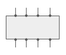
How to connect with each other two switching chips? Well, just the same:
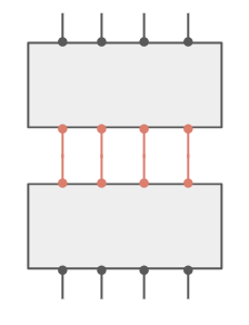
How to connect three chips with each other? Well, probably something like that?
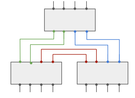
How to tie 8?
Sure? Nothing confuses?
The capacity of the system of 8 chips remains the same as that of the pair - because each time we reduce the number of legs for communication.
The second point is, how do we even create a fully connected topology if there are 16 chips, for example, and each of them has 32 contacts? 16 * 15/2 bundles of cables with 32 cores in each?
This issue was addressed to Klose's non-blocking networks or networks without oversubscription.
We have input switching elements (Ingress FE), output (Egress FE) and transit. The transit task is to associate input with output. Any input is associated with any output through the transit.
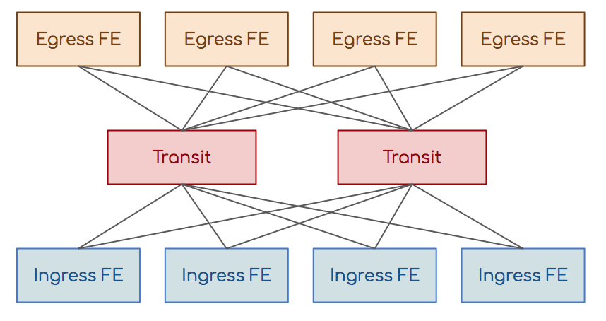
Input and output are not directly connected to each other, transit also have no connection.
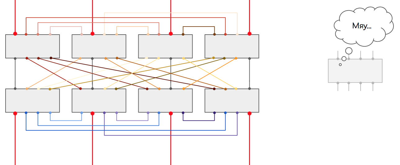
Need more input and output switching elements - add transit. Need more? Add a new cascade of transit:
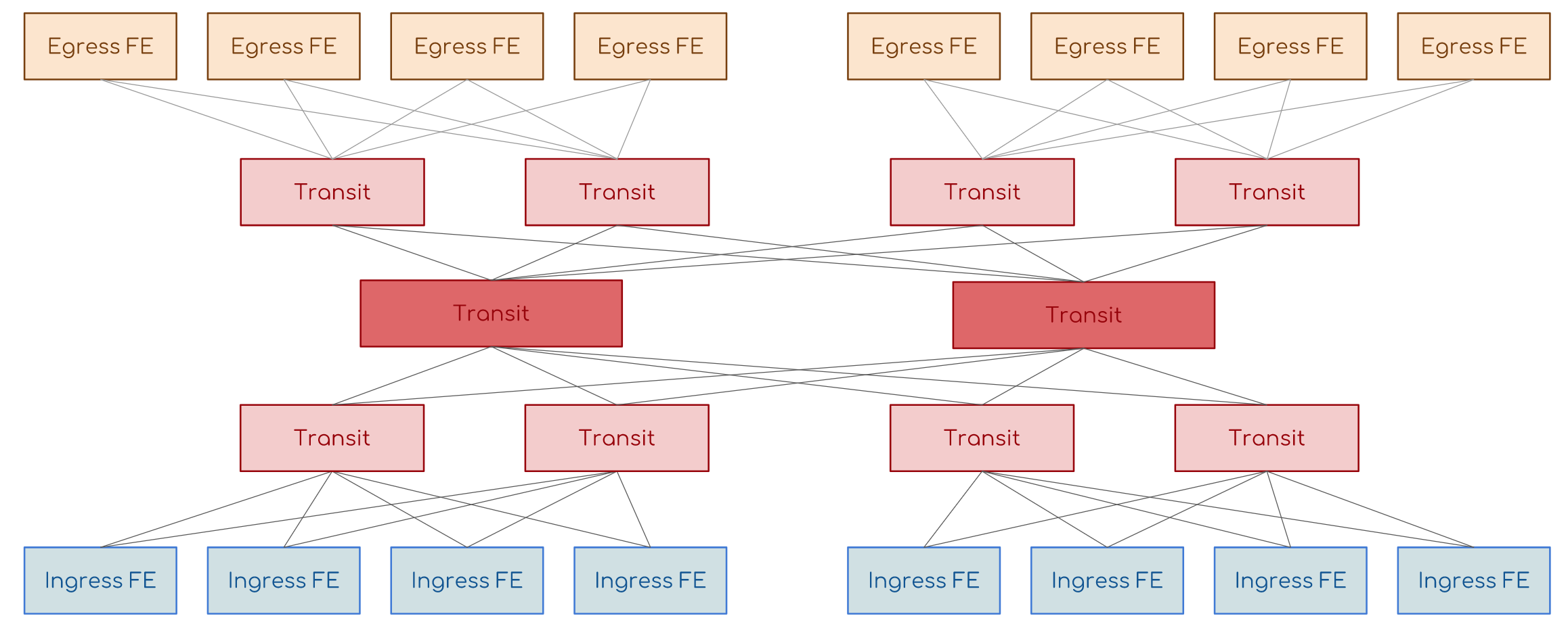
This is what the switching boards in modern routers are crammed with - very stupid ASICs, which only know how to quickly shift packets from input to output.
The switching board is connected to the back bus and has connectivity with all other cards.
Usually they work in the N + 1 mode - that is, everyone shares the load, but when one board fails, the rest take over.
By the way, the boards themselves can be quite called the upper cascade of the Kloz factory hierarchy.
There was only a question on the cells. Well, they would shift these ASICs and packages right away, why else would they be cut?
Here you can draw an analogy with ECMP. If someone has ever set up a per-pack balancing between different paths, then he will surely remember how much pain it caused. Out-of-order packet delivery, which TCP can handle in half, can break IP telephony or video, for example.
The problem with peer-to-peer balancing is that two packets of one stream can easily go different ways. At the same time, one of them is small and reaches the receiver very quickly, and the other accelerate overgrown gets stuck in a narrow buffer. So they are disordered.
The same thing happens in the factory.
A good method of dealing with this is thread balancing - a hash is calculated from a value tuple (SMAC, DMAC, SIP, DIP, Protocol, SPort, DPort, MPLS tag, etc.) and all packets of one stream begin to be transmitted in one way.
But it works imperfectly. Often, one very oily stream can load one link while others will stand idle. And this can be put up with on the operator’s network, but not within this blue box.
An elegant solution is as follows:
Packages are cut into cells of the same small size.
Cells are balanced by cell. That is, one cell here, another - there, the third - in the next link, and so on.
Each cell is numbered, so when it arrives at the desired FE, it is easily assembled back into a complete package.
Since the distance from the input to the output is about the same, the sizes of the cells are the same, the time of their delivery is also about the same.
The idea of Charles Clos, which was first implemented at telephone exchanges, then borrowed into Ethernet switches and then routers, has now found its place in the data center networks, replacing the classic three-tier model.
This is how switching factories look.
Huawei NE40E-X16:

Often the factory is combined with the control module in one slot to save space in the chassis and optimize ventilation.
Juniper:
Huawei NE40E-X8:

Often the factory is combined with the control module in one slot to save space in the chassis and optimize ventilation.
Juniper:
Huawei NE40E-X8:
6. Life's Journey
A package exists exactly within the device. The cable is an electromagnetic pulse.
It is born on the input interface, where the PIC recovers it from the bitstream, and dies on the output, crashing back into them.
Therefore, we can consider finding a package within one device as a lifetime.
Consider two cases - transit packets and protocol packets.
Transit packages
Suppose we are dealing with a standard Ethernet / IP packet.
The node is an IP router.
The package should be in transit from L3 port A to L3 port B.
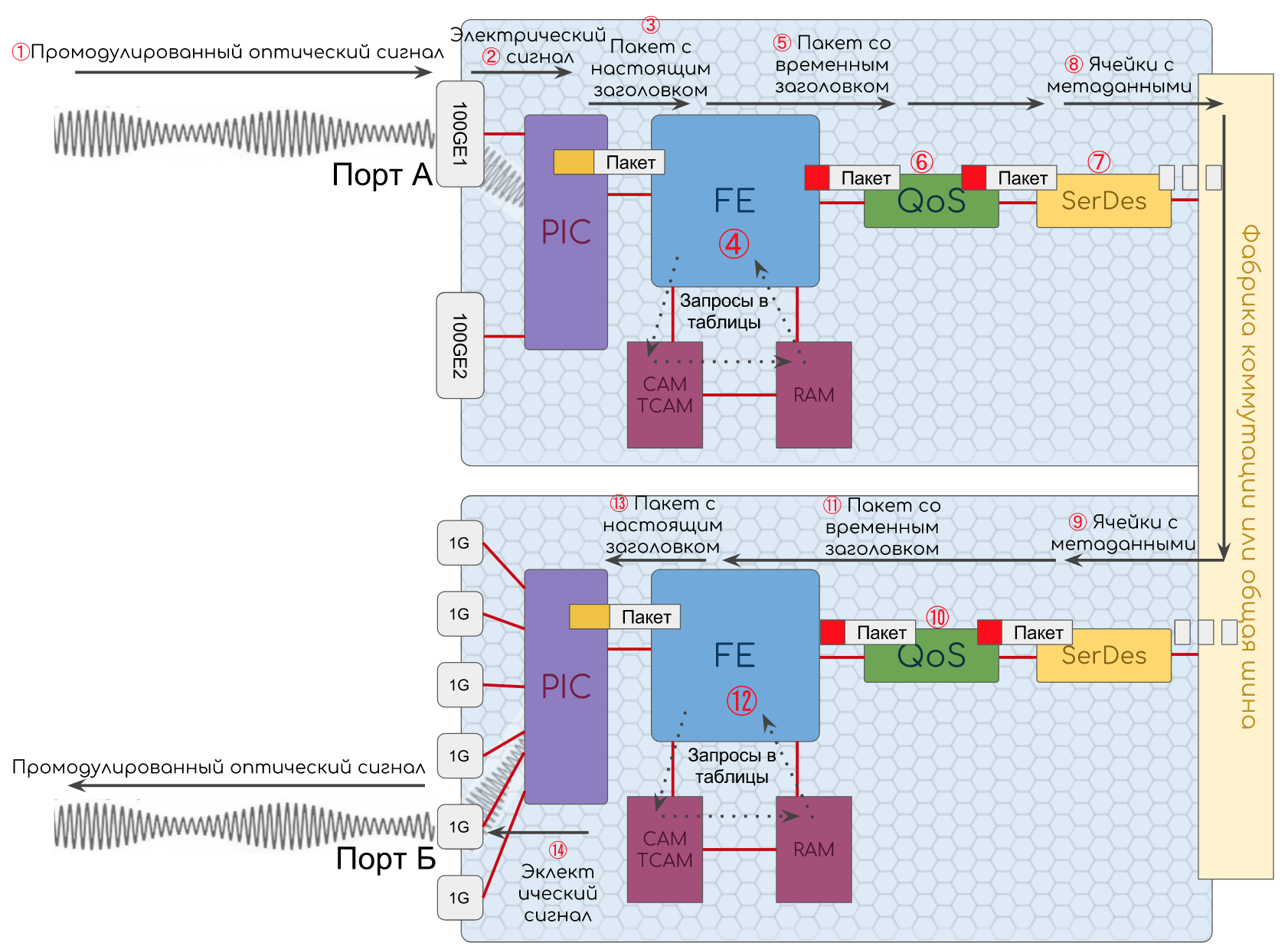
- The optical signal comes to port. Here it is converted into electrical impulses.
- PIC, .
Ethernet Ethernet-. , .
Ethernet . FCS.
, FCS .
— , 1.
PIC : , , Unicast, Broadcast, Multicast. - Ethernet FE.
- FE DMAC , CAM , .
CAM RAM.
Ethernet , DMAC — MAC- . RAM , — Payload IP ( EtherType ).
FE IP (Payload). , .
?- (IP , MAC, MPLS- .)
- (DSCP, IEEE802.1p, EXP .)
- TTL.
- , , (, , ).
, , .- TTL 1 , 0. — CPU ICMP TTL Expired in Transit .
- ACL — .
- DIP .
Ingress FE TCAM , IP-. RAM.
FE RAM Egress FE, NextHop.
Ingress FE MAC- Next-Hop' (Adjacenies Tables).
FE (BUM- , L2VPN), LAG ECMP .( Ethernet), - (BFD, ) CPU (BGP, OSFP .)
- CoS-, . .
, Egress FE:- Egress FE
- A priority
- TTL
- Next Hop (MAC-)
Egress FE , ; — , ; — , , , (DSCP); TTL — , ; Next Hop MAC , DMAC Ethernet-. - . Egress FE.
- , .
- , SerDes .
- .
, .
(2-4), . , .
— , . - SerDes , .
- .
FE (Back Pressure). . CoS, . , .
, .
QoS: , , , .
VOQ (Virtual Output Queue), , : 10 / 13.
PIC. - Egress FE.
- Egress FE :
, TTL, Ethernet, SMAC , DMAC (, MAC Ingress FE, ).
, ( , ). - PIC, , FCS, IFG, .
- , , , .
Most of the local packets are processed by the CPU.
Let me remind you that local are those that were created on this node, which are intended for him (unicast), which are intended for all / many (Broadcast or Multicast) or that intentionally require processing on the CPU (TTL Expired, Router Alert).
Inbox
Right up to FE, the same thing happens with them as with transit ones. Further, the switching chip, turning to the CAM, sees that the DMAC is the MAC address of the local device, looks into the EtherType. If it is any BPDU or ISIS PDU, then the packet is immediately transferred to the desired protocol.
If IP - transmits it to the IP module, which, looking into the TCAM, sees that the DIPalso local - then you need to look in the Protocol field of the IPv4 header (or Next Header IPv6).
The protocol is determined, the decision is made on which module to forward the packet to - BFD, OSPF, TCP, UDP, etc. And so the package unfolds until the end, until the destination application is found.
When Ingress FE coped with this, the contents of the packet are transmitted to the CPU via a special communication channel.
At this step, sufficiently intelligent devices apply a policy to limit the speed of protocol packets transmitted to the CPU, so that telnet alone will not block the processor.
If this packet brought topology change information (for example, a new OSPF, LSA), Control Plane needs to update the Soft Tables (RAM), and then the changes go down to Hard Tables (CAM / TCAM + RAM).
If a packet requires a response, the device should form it and send it back to the original source (for example, TCP Ack on the incoming BGP Update) or send it somewhere further (for example, OSPF LSA or RSVP Resv).
Outgoing protocol packets are formed on the CPU - it fills all the fields of all headers based on Soft Tables and then, depending on the implementation, drops it to Ingress or Egress FE.
- , , . , FE, , FE Lookup .
, , ACL, , .,.
, CPU , , .
There are some Control Plane protocols that are still processed in hardware. A prime example is the BFD. Its timers get out up to 1 ms. CPU, as we remember, is a flexible but clumsy thing, and while the BFD packet passes through the entire path and turns to the BFD header, until the processor reaches an interrupt, until it switches to it, reads the packet, generates a new one, sends tens, and hundreds of milliseconds - looking, and the BFD has already collapsed.
Therefore, BFD packages in most cases are sorted on a chip, and the answer is being prepared on it. And only the session itself is established via the CPU.
The big ones in this matter went even further, transferring the most routine operations to iron.
So, for example, Juniper introduced PPM - Periodic Packet Management , which separates the Control Plane functions of some protocols between the control module and the interface module:
- Bidirectional Forwarding Detection (BFD)
- Connectivity Fault Management (CFM)
- Link Aggregation Control Protocol (LACP)
- Link Fault Management (LFM)
- Multiprotocol Label Switching (MPLS)
- Real-time Performance Monitoring (RPM)
- Spanning Tree Protocol (STP)
- Synchronous Ethernet (SYNCE)
- Virtual Router Redundancy Protocol (VRRP)
. RTT . , , . . ICMP CPU. . RTT , CPU .
ICMP- ICMP- (NP, ASIC, FPGA), CPU. ping .
, ( OAM ), , CFM .
Conclusion
As you have probably understood from the insane amount of ifs, it is impossible to describe hardware switching in a vendor-independent universal language. Worse, even if you take one vendor, its different lines of equipment and even different boards use completely different architecture.
So, for example, Cisco has a platform with software routing, and there is a hardware.
Or on Huawei, the interface queue can be implemented on a TM chip, or maybe on a PIC.
Or where Cisco uses network processors, Juniper manages ASICs.
For a box device, you need to remove the switching factories and search for the output chip.
The routers in the SOHO segment will most likely be missing CAM / TCAM.
Choreography around the queues, which can be done in a thousand different ways, deserves a separate 600 pages in the book The Neighboring Queue moves faster. The history of the lost RFC.
What to say about the modern world of virtualization, where they overthrow the old rulers and enthroned new ones.
In almost every paragraph, an experienced and corrosive reader will find what needs to be clarified, where to give a more detailed explanation. And it will be right ... and wrong at the same time. I had many doubts whether to put the heading “small” or “full-grown”. And I put the “little ones”, because this is only an introduction to the boundless world of hardware switching, which does not require profound knowledge of protocols or electrical engineering, and if I start to dive into the subtleties of implementations of various vendors, I’ll risk never getting out of the swirling whirlpool of parts.
I hope that this article will serve as a starting point in your life-long personal journey.
Thanks
Alexander Clipper , Andrey Glazkov , Alexey Krotov and the linkmeup team for reading the material and comments.
Marat Babayan for providing photos of the equipment.
Artem Chernobay for the illustration.
My two employers, who, by showing patience or by virtue of their ignorance, were allowed to finish this article.
All issues SDSM:
13. Networks for the most experienced. Part thirteen. MPLS Traffic Engineering
12. Networks for the harshest. Part twelfth. MPLS L2VPN
11.1. . №6. MPLS L3VPN
11. . . MPLS L3VPN
10. . . MPLS
9. . .
8.1 . №3. IBGP
8. . . BGP IP SLA
7. . . VPN
6. . Part six.
5. : . NAT ACL
4. : . STP
3. : .
2. . Part two.
1. . Part one. cisco
0. . . Planning
Source: https://habr.com/ru/post/345270/
All Articles