How does the frame render the Metal Gear Solid V engine: Phantom Pain

The Metal Gear series of games gained worldwide recognition after almost two decades ago, Metal Gear Solid became a bestseller on the first PlayStation .
The game introduced many players to the genre of "tactical espionage action" (tactical espionage action), whose name was invented by the creator of the franchise, Hideo Kojima .
But personally, for the first time I played for Snake not in this part, but in Ghost Babel , the spin-off for the GBC console, less well-known, and nevertheless an excellent game with impressive depth.
')
The last part of the franchise, Metal Gear Solid V: The Phantom Pain , was released in 2015. Thanks to the Fox Engine engine created by Kojima Productions , it raised the entire series to a new level of visual quality.
The analysis below is based on the PC version of the game with maximum graphics settings. Part of the information presented here has already become public after the “Photorealism Through the Eyes of a FOX” presentation at GDC 2013.
Analyzing the frame
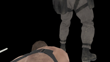
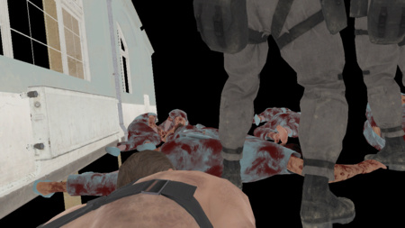
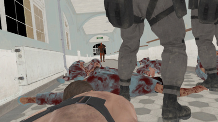
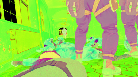
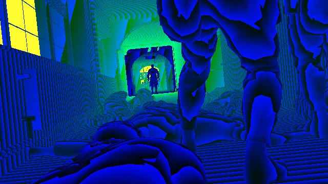
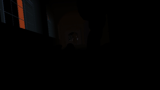
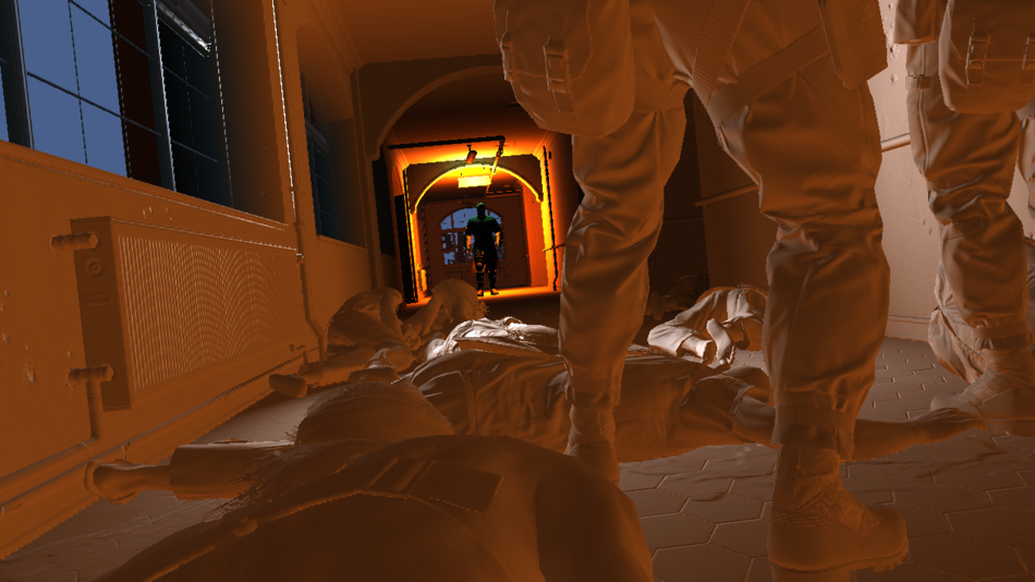
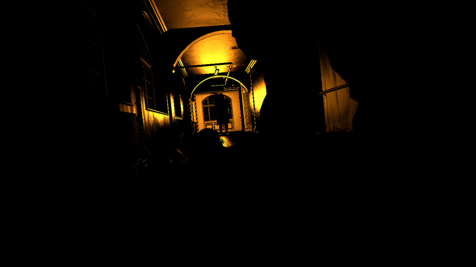
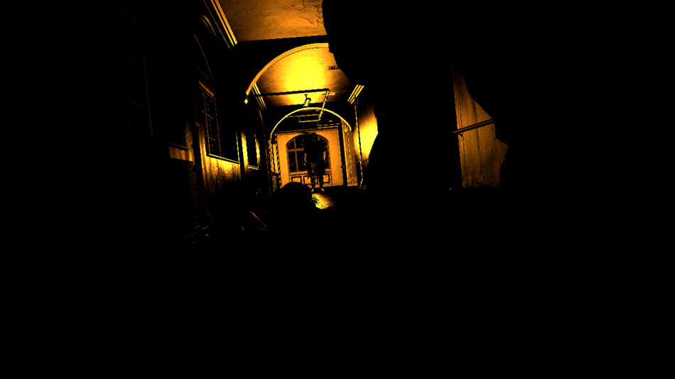
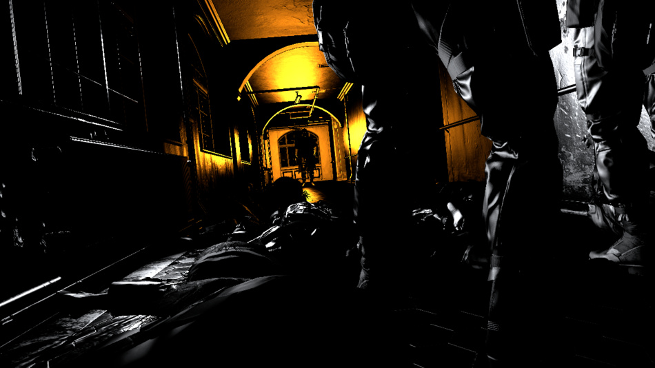
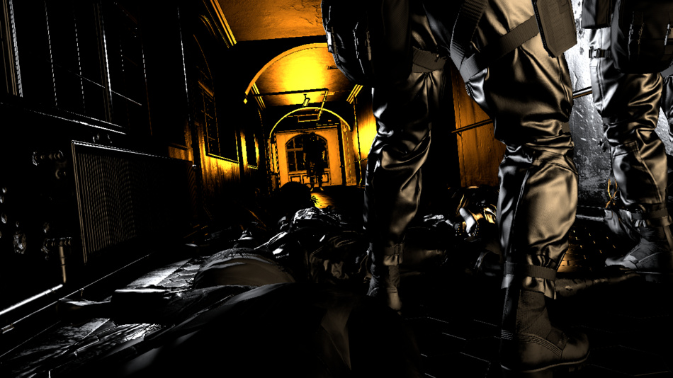
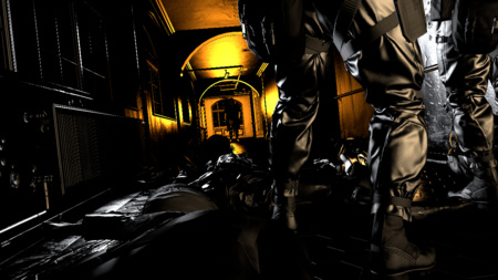
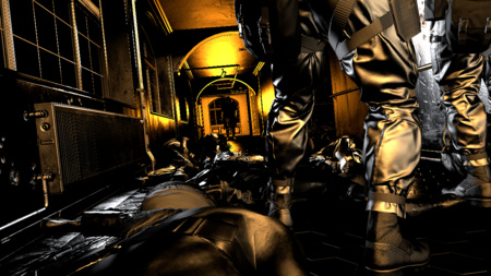
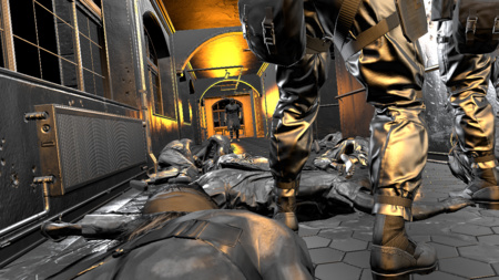
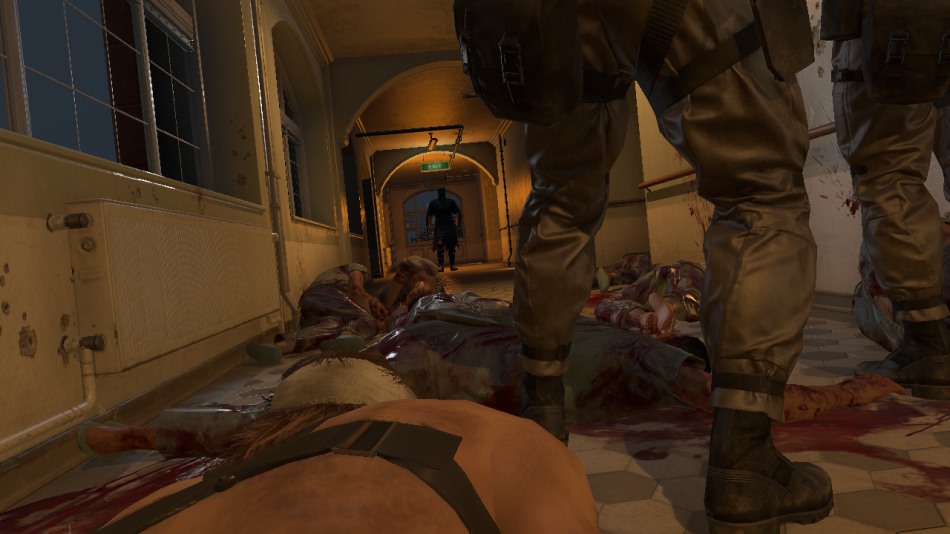
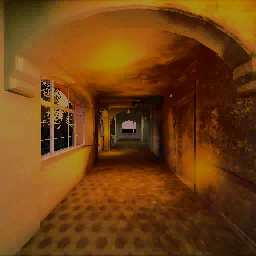
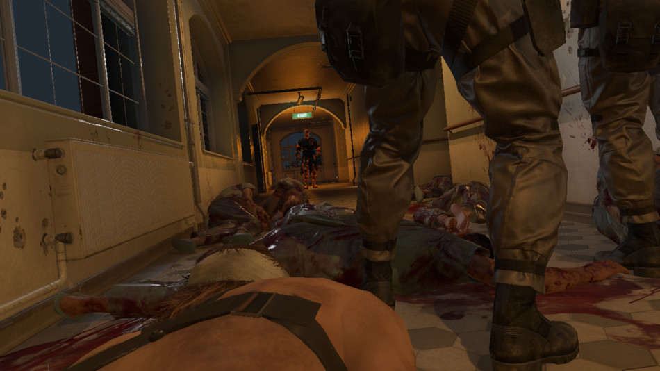
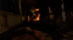
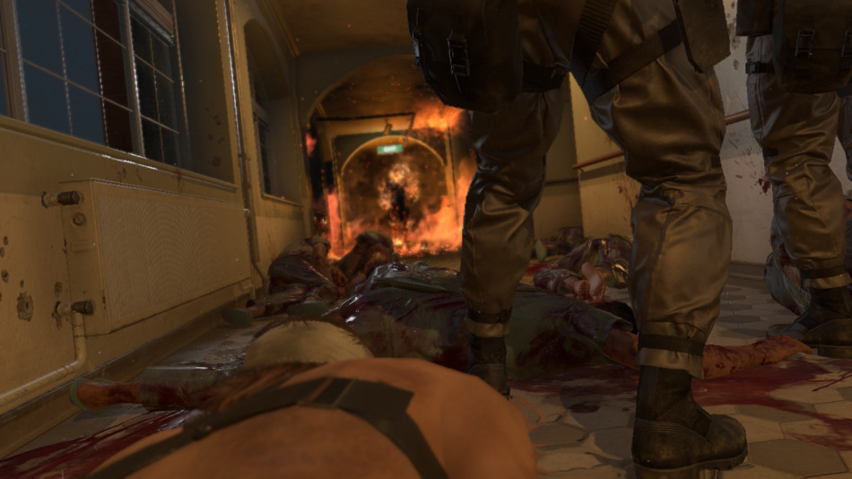
Here is a shot taken from the very beginning of the game: this is the prologue in which Snake tries to get out of the hospital.
Snake lies on the floor, trying to merge with the corpses surrounding him (he is at the bottom of the screen, with a naked shoulder).
This is not the most beautiful scene, but it not bad illustrates the various effects that the engine can create.

Right in front of Snake are two soldiers. They look at the burning silhouette at the end of the corridor.
I will call this mysterious person "man on fire" in order not to spoil the plot of the game.
So let's see how the frame is rendered!
[Approx. Trans .: As usual, in the original article of Adrian there are many animations and interactive elements, so I recommend to get acquainted with them for greater clarity.]
Preliminary passage of the depths
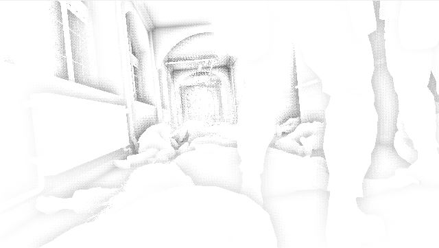
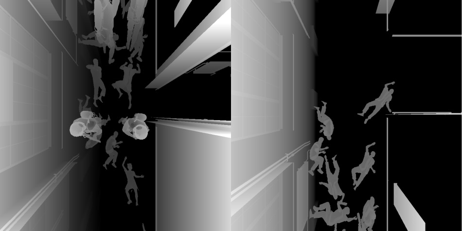
This pass renders only the geometry of the relief under the hospital, how it looks from the player’s point of view, and displays depth information in the depth buffer.
Below you can see the mesh generated from the elevation map of the mesh: this is a 16-bit floating point texture containing elevation elevation values (from the top view). The slider divides the height map into different tiles, and for each tile a draw call is made with a flat grid of 16x16 vertices. The vertex shader reads the height map and on the fly changes the position of the peaks to match the height value. The relief is rasterized in about 150 render calls.

Elevation height

Depth Map: 5%

Depth Map: 10%

Depth Map: 40%

Depth Map: 100%
G-Buffer Generation
In MGS V, as in many games of this generation, deferred rendering is used . If you read my analysis of GTA V ( transfer to Habré), you may notice similar elements. So, instead of directly calculating the final light value of each pixel in the process of rendering the scene, the engine first saves the properties of each pixel (such as albedo colors, normals, etc.) in several target renderers, called G-buffer , and later combines all this information.
All of the following buffers are generated simultaneously:
G-Buffer Generation: 25%
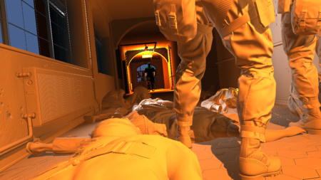
Albedo
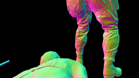
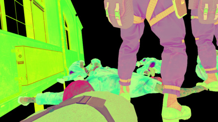
Normals
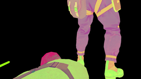
Specular
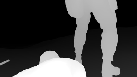
Depths
G-Buffer Generation: 50%
Albedo

Normals
Mirror image

Depths
G-Buffer Generation: 75%
Albedo
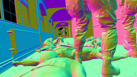
Normals

Mirror image

Depths
G-Buffer Generation: 100%

Albedo

Normals
Mirror image
Depths
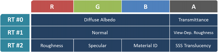
Here we have a relatively lightweight G-buffer with three target renderers in the format B8G8R8A8 :
- Albedo map : RGB channels contain albedo mesh diffuse color, i.e. own color, to which no lighting is applied. The alpha channel contains the opacity / transparency of the material (usually 1 for fully opaque objects and 0 for grass or foliage).
- Normal map : the normal vector (x, y, z) of a pixel is stored in RGB channels. The alpha channel contains a roughness factor , depending on the viewing angle, for some materials.
- Specular map :
- Red: roughness
- Green: specular reflections
- Blue: material ID
- Alpha: translucency for subsurface scattering (this seems to apply only to human skin and hair materials)
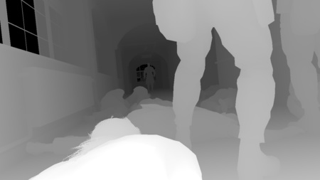
- Depth map : 32-bit float value, indicating the pixel depth. The depth is reversed (value 1 have meshes near the camera) in order to maintain high precision of floating point numbers for distant objects and to avoid Z-collisions . This is important for open world games, in which the drawing distance can be very large.
The G-buffer is rendered in the following order: first, all the opaque meshes of the main scene (characters, hospital building, etc.), then the whole relief (again) and, finally, the decals.
It is here that the preliminary passage of the depths comes in handy: it makes the second stage (relief rendering) very fast. Each pixel of the relief overlapped by another mesh will not have the expected depth predicted by preliminary depths, and in this case it is instantly discarded without the need to obtain texture-related textures and write this data back to the G-buffer.
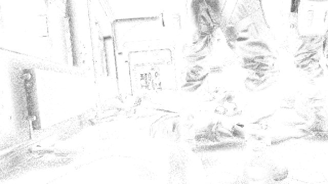
Velocity map
To apply the motion blur effect at the post-processing stage, you need to know the speed of each pixel on the screen.
If the scene is completely static, then the speed of each point is quite simple: it is derived from the depth and difference of the projection matrix between the previous and current frames. But everything becomes more complicated when there are dynamic objects in the frame, for example, running characters, because they can move independently of the camera.
Here the velocity map comes into play: it stores the motion vectors (velocities) of each pixel of the current frame.
Velocity map (dynamic meshes)
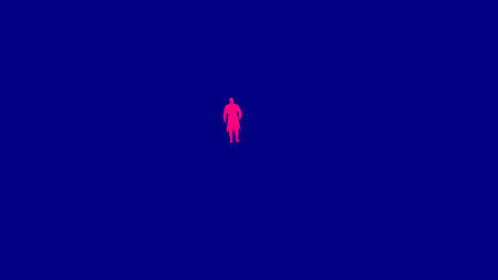
First, the engine generates a velocity map only for dynamic meshes, as shown above.
It can be noted that in our scene only one person in the fire is considered a dynamic mesh. Even if Snake and the soldiers are technically not static meshes, the engine processes them in this way, and in our case this is perfectly acceptable, because they are barely moving. Due to this, the engine can avoid part of the calculations: to calculate the speeds of animated characters, vertex skinning must be performed twice (for the previous and current postures), which can be quite expensive.
The red channel is used as a mask (meaning 1 where the character is drawn), and the velocity vector itself is recorded in blue and alpha channel. A man in fire does not move, so his dynamic speed is (0, 0).
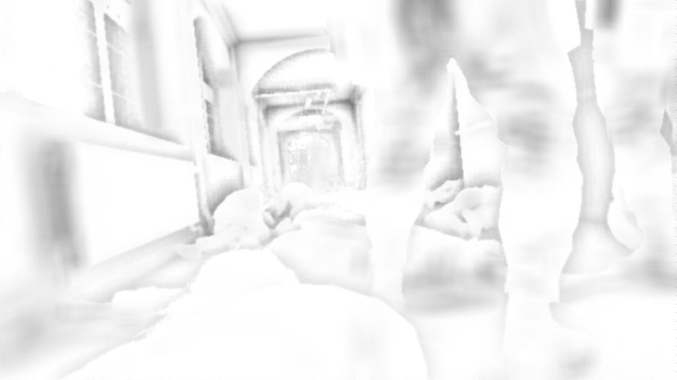
Then the engine calculates the speed of static geometry from the current depth buffer and the last two matrices of projections and combines it over the velocity map of the dynamic meshes, using the red channel as the mixing factor. Here is the final velocity map (static and dynamic):

Velocity map (static + dynamic)
Do not pay much attention to the noise, there is almost no movement in this scene: the camera slowly performs a hit on a person in fire , all pixels have almost zero speed, and what you see is the accuracy of rounding off when writing components to 8-bit channels. I enhanced the colors to make the image more distinct. Also, I swapped the green and alpha channel, the real buffer keeps the speed in the blue and alpha channel.
Screening Ambient Light in Screen Space (Screen Space Ambient Occlusion)
The SSAO effect should add a bit of darkening in areas where there is less ambient light, for example, in narrow holes or in folds. Interestingly, Fox Engine performs two separate SSAO passes using different algorithms and combining the results in the last pass.
SSAO based on linear integrals
Line Integral SSAO (SSAO) is an ambient occlusion calculation technique that Avalanche Software used in Disney's Toy Story 3 game.
Despite the frightening name, this algorithm is quite clear and well explained in this report at Siggraph 2010 : for each pixel of the scene, a sphere is taken with its center in this pixel; this spherical volume is then subdivided into several linear subvolumes. Each sub-occlusion coefficient is calculated by obtaining a single value from the depth map, and the total sphere occlusion coefficient is simply a weighted sum of the coefficients of each sub-subs.
Here, Fox Engine uses two pairs of symmetrical samples, that is, five values of the depth buffer per pixel are included in the original sample.
RGB: linear depth
Alpha: LISSAO
The calculation is performed at half resolution, and the data is stored in the RGBA8 texture, where the alpha channel contains the actual ambient occlusion result, and the linear depth value is stored in RGB (Float-to-RGB encoding is used, similar to this technique ).
The result in the alpha channel is actually noisy due to the small number of samples; This SSAO map can be smoothed later with a depth-based blur filter: linear depth is stored in RGB channels, that is, all the necessary data can be read at a time.
Scalable Ambient Obscurance
SAO
In the second pass of the SSAO calculation, a variation of the Scalable Ambient Obscurance technique is used .
It differs from the “official” SAO in that it does not use any mip-levels of depths and does not reconstruct the normals; it reads directly the height map itself and operates at half resolution, performing 11 readings per pixel (however, using a different strategy for selecting sample locations).
It uses exactly the same mid-tones contrast filtering and a two-sided rectangular filter as in the original SAO implementation.
Notice that the SAO parameters are changed so that the high-frequency variations (for example, at the feet of a soldier) stand out strongly in comparison with the version for LISSAO.
As in LISSAO, the SAO map is blurred by two side passes, taking into account the depths.
After that, the compute shader combines the LISSAO and SAO images, obtaining the final result of the SSAO:
Ready SSAO
Spherical Illumination Maps
To work with global illumination, Fox Engine uses local spherical irradiance maps : different areas are defined at the game level, and a spherical map is created for each of these regions, approximating illumination coming from different directions.
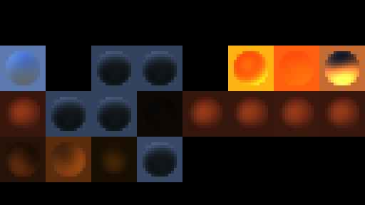
Spherical Illumination Maps
At this stage, one after another, all the spherical maps used in our scene are generated, after which each of them is stored in a 16x16 tile of the atlas of the HDR textures. This texture atlas is shown above: the disk in the middle of each tile is an approximate representation of what would reflect a metal sphere located in the middle of the corresponding illumination zone.
How are these spherical maps generated? They are calculated from spherical harmonics . The underlying mathematics are rather frightening, but, in essence, spherical harmonics are a way of coding the value of a 360-degree signal into a number of coefficients (usually nine) that produce reasonably good accuracy (second order SH ).
And just out of nine of these numbers, you can approximately recreate the value of the signal in any direction.
If you are familiar with the concept of how a Fourier transform can break a signal into sinusoidal components, then the situation is quite similar, except that we decompose the signal into functions on the surface of a sphere.
Where do these coefficients come from? They are precomputed — I assume that the environment of each region, marked up by the level designers, is recorded in a cubic map. Then it is converted into a cubic irradiance map and encoded into the coefficients of spherical harmonics , which the engine reads during the execution of the game.
One may ask: why not use the cubic maps themselves for determining the illumination? This may work, it is possible to use cubic light maps, but they have their drawbacks. The most important is a waste of memory to store the six faces of a cubic map, while spherical harmonics reduce the costs of up to nine RGB values per map. This saves a lot of space in the memory and GPU bandwidth, which is very important when you have to deal with dozens of cards in the scene.
All these spherical maps are generated in each frame from the pre-baked spherical harmonic coefficients and the current position and direction of the player’s camera.
Diffuse Lighting (Global Illumination)
It is time to apply all these generated lightmaps! Each zone affected by the irradiance map is transferred to rasterize the video processor. Usually, each draw call (one per illumination map) sends a mesh in the form of a parallelepiped, which represents the amount of influence of the map in the world. The idea is that it should touch all the pixels that may be affected by a specific irradiance map.
The diffuse map is computed in a half-resolution HDR texture by reading from the normal, depth and illumination maps.
Normals
Depths
Illumination
Diffuse Lighting (GI): 15%

Diffuse lighting (GI): 30%
Diffuse Lighting (GI): 80%
Diffuse Lighting (GI): 100%
The process is repeated for each light map with an additive mixing of new fragments over the old ones.
After accumulating in the diffuse buffer all the lighting brought in by global illumination, it scales from half to full resolution. It is worth noting that increasing the scale is not naive bilinear filtering , it is a bi-directional filter that reads the half-resolution buffer and, more importantly, the original full-resolution depth map (to tie the weights to the adjacent color pixels), so the end result still contains broken edges around mesh boundaries. Visually, it looks as if we all worked in full resolution all this time!

2x zoom (no filtering)
Bilinear 2x zoom
Bidirectional 2x zoom
Sources of non-shadow lighting
After calculating all this static illumination from global illumination, it is time to add dynamic lighting brought in by point and directional light sources. We will work in full resolution and render one after another the volumes of influence for each light source in the scene. For now we will only render sources that do not drop shadows:

Diffuse lighting: 5%

Diffuse lighting: 30%
Diffuse lighting: 60%

Diffuse lighting: 100%
In fact, simultaneously with the update of the diffuse illumination buffer, another full resolution HDR-render is rendered: the reflected illumination buffer. Each call to the light source rendering above is actually simultaneously writing to the diffuse and reflected lighting buffer.
Reflected lighting: 5%
Reflected lighting: 30%
Reflected lighting: 60%
Reflected lighting: 100%
Shadow maps
One can guess what we will do after sources without shadows: sources of lighting casting shadows!
Such sources are much more costly to calculate, so their number in games is rather limited. The reason for their high cost is that each requires the generation of a shadow map .
In essence, this means re-rendering the scene from the point of view of each light source. On the ceiling of the corridor, we have two directional light sources shining down, and each one generates a 4k x 4k shadow map.
Two shadow maps
Light sources casting shadow
After the generation of shadow maps has been completed, the illumination from two directional sources on the ceiling is calculated. Diffuse and reflected light buffers are updated at the same time. Finally, solar lighting is applied (from a previously generated spherical map of spherical harmonics).

Diffuse lighting 0%
Reflected lighting 0%
Diffuse lighting 30%
Reflected lighting 30%
Diffuse lighting 70%
Reflected lighting 70%

Diffuse lighting 100%
Reflected lighting 100%
Combining lighting and tonal compression maps
At this stage, all previously generated buffers are combined: the color of albedo is multiplied by the diffuse illumination, and then the reflected illumination is added to the result. Then the color is multiplied by the SSAO value and the result is interpolated with the fog color (which is extracted from the fog search texture and the depth of the current pixel). Finally, tone mapping is used to convert from HDR space to LDR . The alpha channel stores additional information: the original HDR brightness of each pixel.
Depth | Albedo | Diffuse lighting | Indirect lighting | SSAO |

Lighting combination
By the way, what kind of tonal compression map is used in MGS V? In the interval from 0 to a certain threshold (0.6) it is completely linear and returns the original value of the channel, and above the threshold the values slowly tend to the horizontal asymptote.
Here is the function applied to each RGB channel, where , but :
$$ display $$ ToneMap (x) = \ begin {cases} x & \ text {if $ x \ le A $} \\ [2ex] min \ left (\ text {1,} A + B - \ large { \ frac {\ text {$ B $ ²}} {x - A + B}} \ right) & \ text {if $ x \ gt A $} \ end {cases} $$ display $$
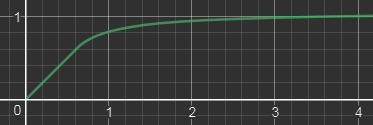
So, for the transition from the linear space to the sRGB space, tone mapping is applied as well as gamma correction . In other games, this often means that we have reached the final stages of frame rendering.
But is this really the case? No way, we're just starting! Interestingly, Fox Engine performs tonal compression quite early and continues to work in the LDR space, including passes for transparent objects, reflections, depth of field, etc.
Radiant and transparent objects
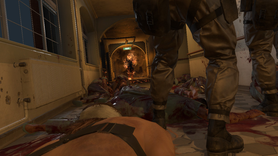
In this passage, the engine draws all objects with the emissivity property, for example, a green “Exit” sign or red hot flame spots on a person in a fire . Also, the engine renders transparent objects, such as glass.
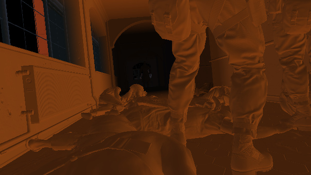
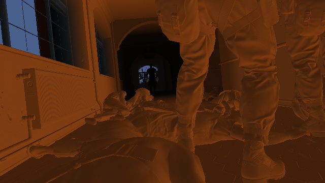
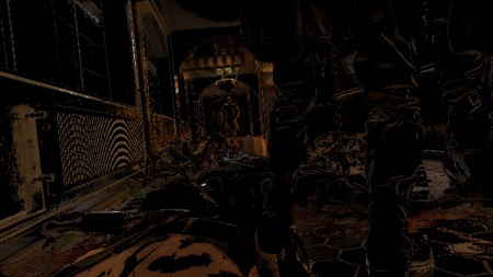
Radiant and transparent objects: before the passage

Radiating and transparent objects: after the passage
In the screenshot above, it is not very noticeable, but in the case of glass, reflections from the environment are also applied.
All environmental data is obtained from a 256x256 cubic HDR map shown below (also called a reflection probe).
Reflection Probe The
cubic map is not dynamic, it is pre-baked and is used as it is in the course of the game, so we will not see dynamic meshes inside. Its task is to create “sufficiently good” reflections from the data of a static environment. There are several probes in different places of the level. The total number of cubic cards of the whole game is huge - not only probes are required for many locations, but also different versions of the same probe, depending on the time of day / night. Plus, it is necessary to take into account different weather conditions, so for each time of day and every point the engine generates four cubic maps (for sunny, cloudy, rainy and thundery weather). The game has to deal with an impressive amount of combinations.
At GDC 2013 they showed a short clip on how the engine generates such lightning probes.
Screen Space Reflections
At this stage, an image of reflections in the scene is created solely on the basis of information from pixels rendered in the previous passage. Here, ray tracing is performed in the screen space at half resolution: several rays are “thrown” at each pixel of the screen, the direction of these rays is calculated from the depth buffer (which gives us the pixel position) and from the normal. Each ray is checked for collision by sampling the depth buffer at four equidistant points along the ray. If a collision is detected, the color of the pixel at the point of its origin is used as the reflection color modulated by the roughness of the original pixel.
SSR color

Alpha SSR
Obviously, we lack “global” information: no object outside the screen can contribute to the reflection. To make artifacts less visible, the reflection map uses an alpha mask to smoothly darken the opacity as it approaches the edges of the screen.
The value of SSR lies in the fact that they can provide dynamic reflections in real time at a fairly low cost.
The noise of the SSR card is later reduced by using a Gaussian blur and blends across the stage.
Heat distortion, decals and particles
The temperature of a burning area in which a person stands on fire is so high that it creates a distortion of light. This effect is achieved with the help of several draw calls, each of which creates a copy of the entire target render and applies distortion, locally stretching the pixels in some direction.
This is especially noticeable on the first arch connecting the left wall with the ceiling.
After that, decals are applied, for example, liquid on the floor, and finally particles are drawn to render fire and smoke.
The foundation

Distortion

Decals

Particles 30%
Particles 60%

Particles 100%
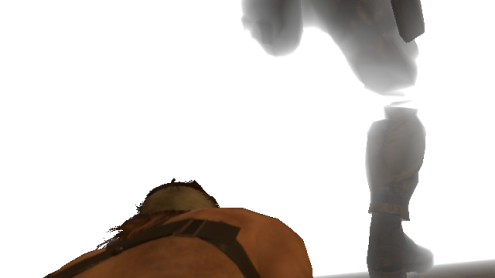
Bloom
Lightness Pass
At this stage, a bloom texture is created from the source scene. It works with very low resolution: first, the scale of the scene is reduced four times, then the lightness pass filter is applied to select only the brightest pixels, as shown in the image above.
How does the lightness pass filter separate the “dark” and “bright” pixels? We are no longer in HDR space, the tone mapping has brought us to the LDR space, in which it is more difficult to determine which color was originally light.
Recall that the alpha channel of the scene buffer contains the original HDR brightness of each pixel before tonal compression — this information the filter uses to determine the "lightness" of the pixels.
Glare in the lens
In the Fox Engine, the bloom effect refers not only to bright pixels spreading around its color: it also takes into account lens flare and chromatic aberration , which are procedurally generated from the lightness pass buffer. In our dark scene there are no strong sources of illumination, due to which the lens flare could stand out, they are barely visible, but you can understand how they look in the above image, where I have artificially emphasized colors.
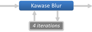
Glare from the lens is superimposed on the lightness pass filter, and then a blurred version of the larger-radius buffer is generated. This is done by four successive iterations of the Masaki Kawase blur algorithm .
The Kawase technique makes it possible to achieve a blur of a large radius, similar to a Gauss blur, but with higher performance .
|  |  Bloom |
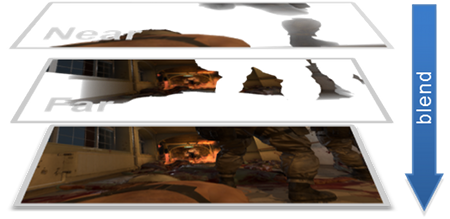
Depth of field
Metal Gear games are known for their long cinematic clips, so it’s natural that the engine tends to recreate the behavior of real cameras as accurately as possible using the Depth of Field (DoF) effect: only a specific area looks sharp, while other out-of-focus areas look blurry.
The scale of the scene is reduced to half the resolution and converted back from sRGB space to linear space.
Then the slider generates two images corresponding to the “near field” (the area between the camera and the focal length) and the “far field” (the area outside the focal length). Separation is performed only on the basis of the depths (distance from the camera) - all pixels are closer than the soldiers, will be copied to the near field buffer, and all the others - to the far field buffer.
Each field is processed separately, a blur is applied to it. The scattering circle of each pixel is calculated only on the basis of the depth and configuration of the camera (aperture, focal length ...). The value of the scattering circle tells you how “out of focus” a pixel is - the larger the scattering circle, the more the pixel spreads around.
After performing the blur, two fields are created:
 DoF - near field |  DoF - far field |

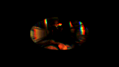
I will say a few words about this “blurring” operation: in fact, this is a relatively expensive operation in which one sprite is created and rendered for each pixel in the scene.
The sprite itself contains a disk, which is shown above, and it can be replaced with any shape, for example, a hexagon, if you prefer hexagonal bokeh.
The sprite is centered on the pixel that created it, it has the same color as the pixel, and its size is scaled along with the pixel scatter circle. The idea is that the pixel “spreads its color around” with the help of a disk - the more pixel is out of focus, the more sprite it needs to be.
All sprites are drawn on top of each other with additive blending.
This technique is called sprite scattering; It is used in many games, for example, in the Lost Planet series, The Witcher and in the post - processing of Bokeh-DoF UE4 .
After generating the blurred far and near fields, we simply mix them over the original scene:
DoF: before
DoF: after
This technique works and creates beautiful results, but at high resolution in almost completely defocused scenes, it can become very braking: overlapping huge sprites can lead to a wild number of redraws.
How does the Fox Engine manage to weaken the effect of this effect?
Well, in fact, I oversimplified my explanations when I wrote that one field is represented by a buffer of accumulation of half resolution: there is not only one buffer, there are several more, smaller size: 1/4, 1/8, 1/16 from permissions. Depending on the pixel scattering circle, the sprite it creates results in one of these buffers: usually large sprites are written into low-resolution buffers to reduce the total number of affected pixels.
To do this, the buffer processes the level of each buffer one by one, creating 100% sprites and allowing the vertex shader to “kill” sprites that do not belong to the current level. The vertex shader knows the size of the sprite, and if the size does not fit the current level, the shader simply throws it out of the visibility pyramid. assigning it a negative depth value.
Geometry of the sprite never gets to the rasterization stage performed by the pixel shader.
Then all these buffers are combined to create a single half-resolution field.
Dirt on the lens and new lens flare

Dirt and glare 30%

Dirt and glare 60%

Dirt and glare 100%
Snake is in a difficult situation and in a hostile environment, explosions are heard around, some projections cross the camera lens and pollute it.
To reflect this effect, some dirt is artificially added to the lens over the image. Dirt is generated from sprites.
Then we need even more glare on the lens! Yes, we have already added them, but there is little glare, right? This time we add artifacts of anamorphic lenses : long vertical streaks of light in the middle of the screen, arising from a bright flame. They are also generated only from sprites.
All of these steps are performed in a dozen render calls that render into a half-resolution buffer, which is then combined on top of the scene with additive alpha blending.
Dirt and glare: up to

Dirt and glare: after
Motion blur
Remember that we generated a velocity buffer at the very beginning of the frame? Finally it is time to apply motion blur to the scene. The technique used by the Fox Engine engine was inspired by an article from the MHBO 2012 .
It generates a low resolution map with square tiles containing the maximum pixel speed. The image of the scene is locally stretched along the direction of the velocity vectors to create the impression of movement.
In our scene, the motion blur effect is difficult to visualize, because there is almost no motion in it.
Color correction
Color correction is performed to adjust the final color of the scene. Artists must balance colors, apply filters, etc. All this is done by an operation that takes the original RGB value of a pixel and matches it with the new RGB value; work takes place in the LDR space.
In some cases, you can come up with some kind of mathematical function that performs this conversion (this is what the tonal compression operator does, which transforms from HDR to LDR), but usually artists need more control over color conversion and no mathematical function can cope with it.
In this case, we have to accept and apply the brute force method: use the lookup table (LUT) comparing each possible RGB value with another RGB value.
Sounds crazy? Let's estimate: there are 256 x 256 x 256 possible RGB values, that is, we have to store more than 16 million comparisons!
It will be difficult to effectively feed them to the pixel shader ... if we don’t resort to any trick.
And the trick is to consider the RGB space as a three-dimensional cube, defined in three axes: red, green and blue.
 RGB cube | We take this cube to the left, cut it into 16 “slices” and store each slice in a 16 x 16 texture. As a result, we get 16 slices, which are shown on the right. |  LUT |
So, we "sampled" our cube to 16 x 16 x 16 voxels, that is, only 4,096 comparisons, which is only a small fraction of the 16 million elements. How do we recreate intermediate elements? With the help of linear interpolation : for the desired RGB color, we simply look at 8 of its closest neighbors in the cube, the exact mapping of which we know.
In practice, this means finding two layers that are closest in value to blue, and then searching each layer for the four nearest pixels by the value of red and green.
Then, linear interpolation is simply performed: a weighted average of eight colors is calculated taking into account the distances affecting the weights. Such interpolation from a smaller number of values works well, because color correction is usually performed with low-frequency variations.
You can save 16 layers in a 3D texture inside a video processor, and the shader code becomes very simple: just request a search for certain 3D coordinates, the equipment performs trilinear filtering of the eight nearest points and returns the correct value. Quick and easy.
So, we have a way to encode color matching using this lookup table based on 16 slices, but how does the artist actually create such a table?
It's simple enough: just lay out all the cuts next to each other to get a similar image:

256x16 LUT texture
Then we take a screenshot of the game in the scene that needs color correction. We insert the LUT image into any corner of the screenshot, give the image to the artists and allow them to create all the magic. They use a graphic editor, make the necessary changes, and then send us the corrected image. The corner-built LUT will reflect the new RGB color matching.
Now you can simply extract the modified LUT 256x16 and transfer it directly to the game engine.
Color correction + Bloom: up (LUT:
)
Color correction + Bloom: after (LUT:
 )
)At this stage, before applying color correction, a buffer bloom is added over the scene.
Anti-aliasing
The edges of the meshes repeat the pixel grid of the frame buffer too much, so we see sharply broken boundaries that look unnatural.
This is a limitation of deferred rendering: each pixel stores only one information; in direct rendering, this problem is less pronounced, because MSAA can be used, which creates multiple samples of color per pixel, which provides smoother transitions on the edges.
Fox Engine corrects aliasing on the edges, performing the FXAA post-processing stage: the pixel shader seeks to recognize and correct distorted edges based on the color values of adjacent pixels.
Notice how the “ladder”, clearly visible at the border of the railing, is smoothed in the final result.

FXAA: up to

FXAA: after
Finishing touches
Have we finished anti-aliasing? Almost, but not quite! At the last stage, artists have the opportunity to put masks on certain areas of the image in order to darken or lighten pixels. This is just a series of sprites drawn on top of the scene. It is interesting to see how much Fox Engine allows artists to control the image even at the very last stage of rendering.

Final touches: 0%

Final touches: 30%

Final touches: 60%
Finishing touches: 100%
And we are done! Now the frame can be transferred to the monitor, and the video processor will start the same process from scratch to generate a completely new frame.
Some metrics of this scene: 2331 draw calls, 623 textures and 73 target renders.
Bonus notes
Look at the buffers in action.
Here is a short clip showing the different buffers that I talked about earlier (G-Buffer, SSAO, etc.).
If you are interested in how the video was recorded: the analysis of this game compared to the previous ones required much more effort. None of the graphical debuggers could be used here, because MGS V shuts down when it detects DLL injectors that modify certain D3D functions. I had to roll up my sleeves and forked the old version of ReShade , which I expanded with my own interceptors. Thanks to them, I could save buffers, textures, shader binary data ( DXBC containing all the debug data) ...
Thanks to my interceptors, it became quite simple to create the video shown above: I could just copy any intermediate buffer into the final frame buffer just before it was transmitted to the monitor.
The true face of Ishmael
Ishmael is a mysterious patient lying in a bed next to Snake who helps him escape from the hospital. His head is wrapped with bandages that hide his true identity. It was interesting to you to find out, how does he look like in reality?
Well, let's see! Here is the diffusion buffer albedo immediately before and after rendering the bandage.
There are no spoilers , but just in case I hid the second image.


This ... is not exactly the face that should be
But let's take one more step!
Instead of simply saving the albedo map in the middle of generating the G-buffer, as I did before, it would be nice to see Ishmael's face during the game itself, forbidding the engine to render the bandage.
It's pretty easy to do: thanks to my own interceptors, I can disable the transfer of certain calls to the video processor. A little experimenting, I found two render calls that render the dressings, and sent them to the blacklist.
If you want to repeat the experiment yourself, here are the necessary challenges:
ID3D11DeviceContext::DrawIndexed( 0x591, 0xF009, 0x0 );
ID3D11DeviceContext::DrawIndexed( 0xB4F, 0xFA59, 0x0 );
Below is a video of the game with the true face of Ishmael. I use the hot key to switch rendering the armband. The transition is progressive and reduces the number of triangles used to draw the dressing to complete darkening.
It is worth noting that this trick with blocking draw calls does not work in all cases - sometimes the source mesh simply does not contain data for hidden surfaces. This is logical, because it allows you to optimize performance: less unnecessary geometry is transferred to the video processor!
For example, the model of the “third child” does not have triangles under a gas mask in the lower part of the face, we will never see its nose and mouth, simply because they do not exist.
Additional links
This completes the MGS V analysis. I hope you become better at understanding how Fox Engine renders the frame.
If you want to know more, below I provide links to additional materials:
- Photorealism Through the Eyes of a FOX: The Core of Metal Gear Solid Ground Zeroes (GDC 2013); report Kojima Productions
- Tech Analysis: Metal Gear Solid 5's FOX Engine ; Digital Foundry Report
- In MGS V PBR Texture Analysis, the game map formats are documented.
- MGS V NVIDIA Performance Guide with details on graphic settings.
- Special thanks to Patrick Mours for revealing the ReShade source codes this year.
Source: https://habr.com/ru/post/344916/
All Articles