Introduction to VxLAN

Today we will talk about another interesting technology - VxLAN - what kind of beast it is and what it is eaten with, and whether you really need it. My acquaintance with this technology began with the study of hypervisors - I constantly came across the term VxLAN, but I didn’t know how it works. One day, I decided to still read what kind of beast. After reading a couple of articles, I learned for myself the main aspects of the technology and exhaled with relief, having read that this technology is the inheritance of hypervisors and to the transport is indirectly related (although, as it turned out later, the relation of VxLAN to transport has the most ). After that, I safely forgot about the technology and I returned to it again only a year later, when I started to dive into EVPN - most of the articles and manuals were about the symbiosis of EVPN and VxLAN. There is a lot of literature on this technology, especially if you speak English. I will try in this article to tell about the basics of this technology and show it in practice - how it is configured and works. But let's start with MPLS ...
For me, as an engineer who exploits the IP / MPLS network, the most important in this technology is its ability to organize virtual networks of the 2nd and 3rd level (L2CKT, VPLS, L3VPN, 6PE and so on). Any traffic engineering and fastrerouts, although they provide the engineer with very great opportunities in terms of traffic management and increase the number of 9-app decimal points (theoretically, practically everything leads to complication of the network architecture and, as a result, an extension of the accident resolution period), but in fact are an end in itself to deploy an IP / MPLS network. Would mpls be such a popular technology and de facto standard for large, and for small providers, if it were not able to make VPNs? Naturally not. Well, you can hardly agree that you would reshape your network for the sake of introducing engineering traffic.
')
IP / MPLS networks are usually built on high-performance routers, for example, Juniper MX or Cisco ASR9K / 99 (in any case, the core of an IP / MPLS network). For a data center, such equipment is usually not typical, and usually, if routers of such a level are installed in the data center, then they play the role of some PE-NIS or border through which DCI and uplinks are organized. The matter is mostly in the cost of equipment - the cost of one port on the switch is much lower than the cost of a similar port on the router (with similar indicators of throughput, port density per slot, and so on). In data centers, high-performance non-blocking or partially non-blocking switches are usually installed with a high density of ports with a capacity of 1/10/40 / 100G (depending on the type of ToR / EoR / Spine / Leaf equipment), for example, Cisco Nexus, very good Arista or Juniper products.
But the same Cisco Nexus 9K is not suitable for use in the MPLS domain, as it simply does not have support for label distribution protocols, or, for example, Juniper QFX, which MPLS does support, but still has limitations, for example, fib. That is, in fact, it is theoretically possible to launch MPLS in a data center built on Juniper QFX, but in practice it will not be the best solution - at some point you will be faced with the capabilities of this equipment (and this moment will come very soon).
On the other hand, there are many systems in data centers that want to have both L2 connectivity and a geo-backup simultaneously. How to ensure L2 connectivity between servers located in different parts of the network without MPLS? In general, then, if you dig, there are several different solutions to this problem. We, as it is easy to guess from the title of the article, let's talk about the technology specially sharpened for these needs - VxLAN, which allows you to build geographically stretched L2 networks over an ordinary IP network and today is the de facto standard for data centers.
Any service organized on top of an IP / MPLS network is tunneling in one form or another - in any case, we are tunneling through something. For example, let's take a simple L3VPN between point A and B. In the simplest version, without any options C or Detour / Bypass tunnels, we have a stack of two tags - the bottom one, the service tag and the top one, transport one. Naturally, to put some kind of service between points A and B into a tunnel, we need the end-to-end tunnel itself between these same points A and B. LDP / RSVP-TE LSP acts as such a tunnel in IP / MPLS . Further, no one forbids us to put another tunnel inside this transport tunnel, which is intended for forwarding client traffic.
As a result, we get a tunnel that is tunnelled through another tunnel. That is, ultimately it turns out that one network (client network) is built on top of another network (provider network). The provider's network is called the underlay network. In essence, this is the foundation for building superimposed networks — VPNs. Client networks deployed over the underlay networks are overlay networks and are built using some of the existing overlay technologies — for example, the same L3VPN. That is, in VPLS / L2CKT / L3VPN and so on, the IP / MPLS network is used as the underlay and the same MPLS as the overlay.
But what if we do not have MPLS, and we need L2VPN (to be more precise, then VPLS)? As I said earlier - there are various technologies that allow you to do this, we will stop VxLAN. This technology, in conjunction with UDP, can organize a virtual L2 multipoint network (essentially an analog of VPLS) without using MPLS tags over any IP network (it can work over IP / MPLS networks — then you will see that only IP connectivity is important) . Immediately a lot of questions arise, for example, what plays the role of a tunnel in underlay or what is used as a service tag in overlay? We will answer these and some other questions further.
So, VxLAN is a virtual extended private network (Virtual eXtensible Local Area Network). In the literature, you can find another name MAC-in-UDP. This is all the same VxLAN, and the second name describes the essence of the technology much better. As you guessed, VxLAN is a technology that allows ordinary ethernet frames to be packed into UDP segments and transported in this form over an IP network. I think so far that little is clear, so let's take a closer look.
In an IP / MPLS network, routers usually have some specific purpose — for example, PE, P, or ASBR. PE routers are multiservice aggregation nodes. In simple terms, these are the nodes to which client services are connected - it is on these nodes that the L2 / 3VPN, VPLS, and other VPN services that run on top of the IP / MPLS network start (end of the last mile and all sorts of options). A / B / C we are not considering). The second important element of an IP / MPLS network is level P routers - essentially just traffic threshers (especially if you have Free Core), who do not even realize that they are involved in organizing any VPN services.
VxLAN technology also has such nodes, only they are called a little differently, although they perform essentially the same functions. The analog of the PE router is VTEP - Vitual Tunnel End Point. It is VTEP that is a service aggregation node, and VTEP can be not only a ToR / EoR / Leaf switch or PE router, but also a regular server, if it has the necessary software (for example, VMWare can do this). As in IP / MPLS, VxLAN tunnels begin and end at VTEP. Analogous to a P-level router are routers / switches that do not terminate clients and simply forward IP traffic - these switches usually do not even know about the existence of tunnels in the VxLAN network (if they were not carried out, for example, gateways).
It is always easier to explain something with an example, so before moving on to the basic principles of VxLAN, let us recall another very important and well-known technology for all of us - VLAN.
VLAN is a technology designed for network segmentation at the second level. As we all know, the standard switch produces frame forwarding based on the forwarding table (built by himself in the process of work), which takes into account not only the mac address of the frame, but also its vlan tag. If we draw an analogy of VLAN with VRF, then each vlan is easiest to consider as a separate virtual entity - that is, a virtual switch. By issuing the vlan 100 command on Cisco, we create a virtual switch with a tag of 100. Each virtual switch created by us has a certain set of interfaces (by allowing the interface on a certain interface, we add a port to a specific virtual switch), as well as a table of correspondence mac addresses and ports (we see it with the command show mac-address-table dynamic vlan 100).
Theoretically, we can imagine that when a frame with a vlan tag arrives at some switch port, then the decision to further send the frame is made on the basis of the mac table of addresses of the corresponding virtual switch. If a frame with a tag of 100 is received, then the decision to forvard this frame will be made based on the mac of the virtual switch table with a tag of 100.
A classic switch when receiving a frame (for us it doesn't matter what frame it is - broadband or unicast) floods it into all of its ports. If the switch has a reason not to flood the packet to any port or group of ports, it will not do this: if the switch knows for sure, no matter where it is that the destination mac is not located at a specific port or that the frame is sent to a specific port or Since the ports are not needed (well, for example, igmp-snooping is enabled), then the switch will not flood the frame into this port (or ports). It is logical that when you receive a frame, the switch has at least a reason not to flood this frame back to the port from which it came - this is a banal horizon splitting rule. If the switch knows for sure that the destination mac address lives behind a certain port, the frame will be sent to only one specific port. Based on the foregoing, the logical switch can be represented as follows:
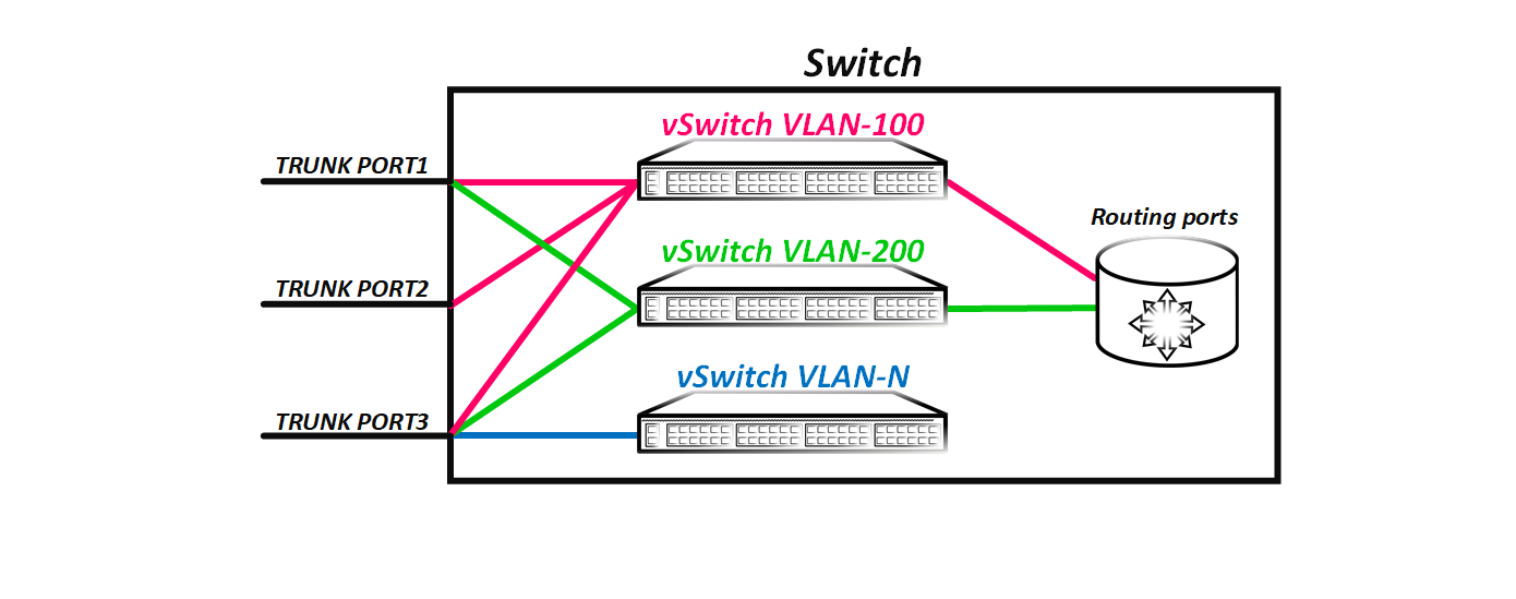
As you can see from the picture, it turns out that the frame that came with the tag 100 100 enters the virtual switch 100 and it is logical that now it cannot just get into another virtual switch — that is, another vlan, well, for example, 200, because There is no direct connectivity between virtual switches. When we create a routing interface, we create an interface through which a virtual switch can communicate with other virtual switches that also have a routing interface - that is, route packets between vlans.
The diagram shows that the virtual switches VLAN-100 and VLAN-200 have routing interfaces through which these virtual switches can communicate. At the same time, the virtual switch VLAN-N does not have the L3 interface configured - that is, this virtual switch does not have the ability to communicate with other virtual switches (in our case with VLAN-100 and VLAN-200). The Vlan number in the classic L2 network is global - if we have an L2 domain from, for example, 10 switches, then the Vlan numbers are global for the entire domain.
But we must understand that this is just a simplified logical model of the switch for understanding the principle of its operation. And although the vlan can be thought of as a virtual switch, in reality it is not. That is, we do not have a separate switching table for Vlan 100 or Vlan 200. Naturally, we can see which poppies we studied in a particular vlan (and you can see that the same poppy can be in different vlans) but this does not mean that a separate table has been allocated for this vlan on the equipment. The switchboard has one single forwarding table, regardless of the number of vlans configured on it. Just when a received frame is flooding, the switch knows that it is not necessary to send this frame to certain ports. For example, if the eth1 / 1 port is an access port in 200 of the 200 and the eth1 / 2 port is a trunk port, but the 100 is not allowed on it, then the switch (meaning physical) will not flood the ports with the tag 100, because knows for sure that there are no hosts in the 100th vlan behind these ports. Physically, this is exactly the case, but it is logically easier to imagine that these ports do not belong to the virtual switchboard with 100 VLAN, and therefore the frame cannot simply be sent to them.
Note: You should not try to apply this concept to bridge domains on modern routers - this is essentially a different world with its own laws, in which the vlan number essentially matters only on the link. All described corresponds to the classic switch, which does not support the extended vlan space. I wrote a separate article about bridge domains (for JunOS). If anyone is interested, I can do a similar article for IOX-XR.
That is, we have the following: we have a virtual switch, defined by some vlan tag and having some set of ports. Exactly the same concept underlies the VxLAN. Only in VxLAN, the role of the vlan tag is played by the VxLAN Network Identifier (sometimes also called the Virtual Network Identifier), or VNI for short. Unlike the vlan tag, which is 12 bits long (that is, there can be a maximum of 4096 vlans in one L2 domain), the VNI is 24 bits long — that is, it can take 16,777,214 unique values. Like the vlan tag, VNI is unique to the entire VxLAN domain. That is, if Host A lives behind VTEP A and Host B behind VTEP B, then on both VTEPs, these hosts must be behind the interface that belongs to the same VNI, otherwise L2 connectivity between hosts A and In will not. Everything is the same as VLAN - after all, if on one switch the host will be in 100 100 and on the next other host in 200, then there will be no L2 connectivity between these hosts.
Note: it is very important to understand that unlike MPLS tags, which are unique only within one node, the VNI identifier has global meaning for the entire VxLAN domain. Therefore, it is very difficult to calculate what will be more L2 networks when using VxLAN or VPLS (with MPLS). Absolute value is natural and points in favor of VxLAN. But if in VPLS you can use the same label for different clients (for example, if VPLS domain 1 on PE 1 uses the label 299001, this does not mean that the VPLS domain 2 on PE 2 cannot use the same label 299001) . But when using VxLAN this number will not work. If you use the same VNI on both PE1 and PE2, then the client connected to PE1 will be able to communicate with the client connected to PE2.
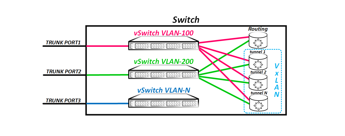
As I wrote earlier, when creating a vlan, we essentially create a virtual switch and then add some ports and a routing interface to it (if necessary). But what ports do we add? Do we have to use physical ports? Or you can use virtual? Recall, for example, a protocol such as GRE. When creating a GRE tunnel, a logical interface is created — for example, gre-0/0/0 on JunOS. Similarly, when creating a VxLAN tunnel, a tunnel interface appears on the switch, for example, vtep.xxx on JunOS. This interface, as we will see later, is trunk and is capable of transferring both tagged and untagged frames. If you have the opportunity to climb on some box and look at the table of MAC addresses in VPLS, then you will see that some of the poppies will not be visible through the physical port, but the logical lsi interface (for example, JunOS). The lsi interface is nothing more than a tunnel (pseudowire in VPLS terms) to any PE router. What is worse VxLAN tunnel? The VxLAN uses the same principle - only the tunnel signaling is different.
As a result, the switch uses the VxLAN tunnels it has as trunk ports, into which, like the real port, packets are flooded and through it examines poppies. That is, if we have several remote VTEPs, then the switch logic will now look like this:
But as I said at the beginning, if the port has a reason not to flood the received frame into any port or group of ports, then it will not do that. By default, the frame is not sent only to the port from which it arrived - this is a simple rule for splitting the horizon. In VxLAN, this rule also works, but there are some nuances.
Suppose a frame is received through a physical port. In this scenario, everything is fine - the switch just floods the packet to all ports (well, except for the port from which the frame was received). But what if the frame is received through a VxLAN tunnel? Since between all VTEPs, a fully connected topology from VxLAN tunnels is created, it is logical that the frame received from the tunnel does not need to be flooded again to other VxLAN tunnels, since the other VTEPs have already received this frame - this is the essence of the fully connected topology .
But how to understand under what circumstances to which ports the frame should flood, and which ones should not? For this, ports that are VxLAN tunnels are combined into a virtual group (let's call it the split horizon group) and if the frame is received from a port that is a member of this group, then the other ports that are in this group will not flood. Naturally, the equipment allows you to change this behavior, for example, for the hub-and-spoke topology. But you just shouldn't do it this way - the broadcast storm is a “fun” thing.
To summarize the first part of our article: VxLAN is an extended analog of VLAN - that is, it is a virtual L2 network. L2 — . VLAN, VxLAN VLAN , L2 — VxALN Network Identifier (VNI). VNI 24 , 16 L2 . VLAN , VNI L2 (VxLAN) . mac flood-and-learn — ( ) source mac . , VTEP- .
, — vpn - -. IP/MPLS underlay IP/MPLS , MPLS overlay. , - . GRE. overlay- , p2p . IP IP , GRE .
VxLAN , . GRE, ethernet VxLAN . 8 VNI. , , , VNI — VLAN . What's next? GRE VxLAN IP . But there is a problem. IP protocol, , , IP . GRE 47, VxLAN . VxLAN IP , , . VxLAN , GTP, UDP, protocol . UDP IP . VxLAN UDP 4789.
— UDP? TCP, , . , TCP — — . , TCP. TCP TCP — . , , , underlay VTEP-A<<>>VTEP-B overlay SERVER-A<<>>SERVER-B. TCP, — . underlay overlay . , underlay TCP , overlay TCP . , — . UDP , UDP , TCP — p2p p2mp — , .
VxLAN :
VNI.
, UDP IP … ? . VxLAN , . , VTEP? .
( ). VxLAN . .
Static (Unicast) VxLAN
— VTEP. VPLS Martini. , VNI VTEP, VNI. VTEP IP — VTEP. , VTEP- , . IP , VxLAN VTEP VTEP-, . , VTEP , VNI VNI ( , ). , , mac source mac, VxLAN VTEP mac , ethernet VTEP, . — VxLAN .
— , BUM VTEP , VTEP VTEP- (). - . , openvswitch , ( ).
VTEP. VxLAN .
Multicast VxLAN
, , VTEP- , underlay, VTEP. VTEP- . , - , VNI ( VNI). , VNI, ( VTEP, ) . ? , VTEP- ( VNI-multicast ) — . , VTEP-. VTEP-.
— VTEP VxLAN , ( IP ), VNI — , VTEP . . VTEP , VxLAN . , — , ( VTEP , VTEP- mac VTEP) .
VxLAN UDP — UDP? p2mp – . TCP p2mp , UDP, .
- bidir-PIM, , VTEP ( ). — , VxLAN VxLAN .
BUM underlay . . VTEP IP . - ( , ) — , VNI- . .
EVPN/VxLAN
, — EVPN control plane VxLAN. - , EVPN, , MPLS/EVPN, VxLAN/EVPN. EVPN/VxLAN – .
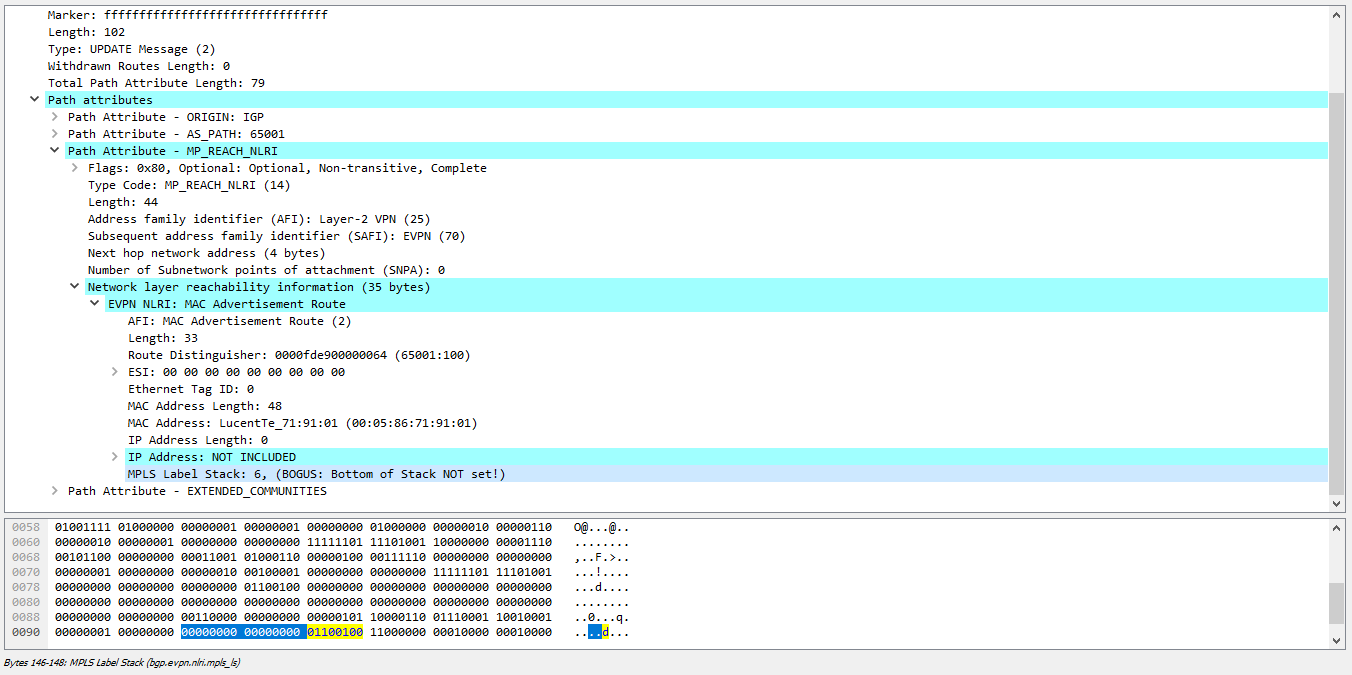
, EVPN — ( ) BGP, VTEP- . , link-state ( ), mac ? EVPN l2vpn (AFI 25). mac BGP — , L3VPN. EVPN/MPLS BGP NLRI mac ( RT/RD/next-hop ) MPLS . — MPLS. , VNI! , BGP VNI.
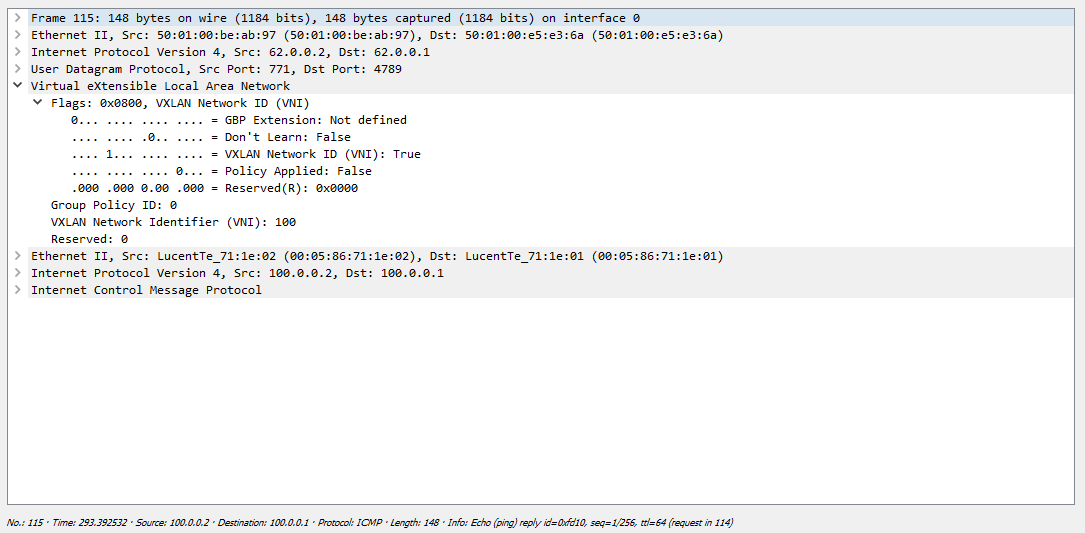
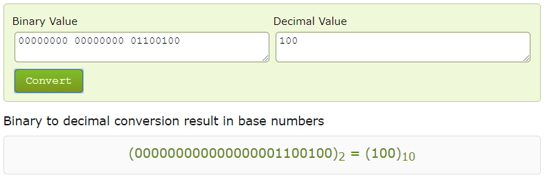
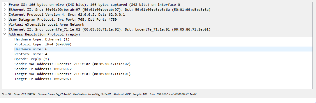
EVPN NLRI 3 — 24 , VNI. BGP VNI. , — , EVPN , MPLS Label VNI, MPLS ? , . Wireshark VNI, MPLS ( 4 , Wireshark 6, VNI 100):
, , vxlan :
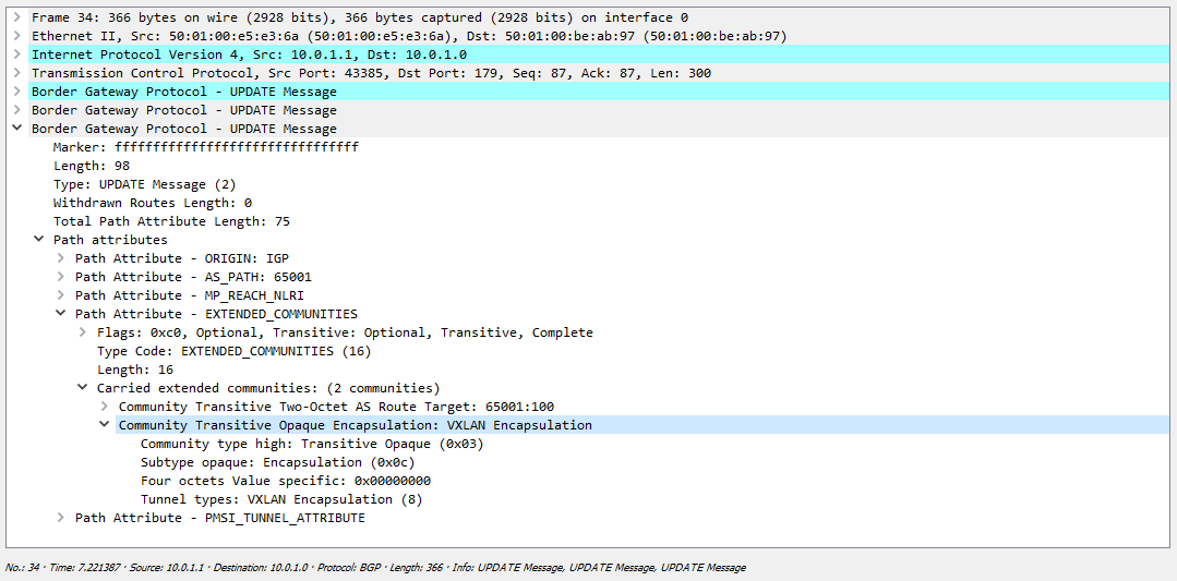
, , VNI:
— 5- ( , 8 , ). -, , ( VTEP), . , - ( RP , , RP).
. EVPN? — EVPN data plane control plane. , , ? -, -VTEP , , data-plane. , , ? , , , ( ).
EVPN — VTEP- mac data plane, BGP , . VTEP-, BGP mac . What does this give us? , , , , mac . , control plane — .
, ? , , - mac , BGP — , mac. mac , . flood-and-learn , EVPN , data-plane control plane. EVPN , .
EVPN? , .
EVPN , Single-Active, All-Active ( MC-LAG). (MLAG -Arista, vPC – Cisco Nexus), EVPN. — EVPN . , L2 ( All-Active, Single-Active ) — . , DF — , BUM . BUM , . , non-DF DF. , DF , .
EVPN/MPLS ESI — , DF , . VxLAN . ? .
EVPN/MPLS , — ESI. 4, ESI ( MC-LAG ) DF, . , ESI, , , ( ). VTEP-, , ESI, . local bias. DF .
EVPN , (Mass Withdrawal), , mac (Aliasing), L3 anycast GW, .
VxLAN
. VTEP , . , , , , , .
, . , VxLAN underlay IP ( ), end-to-end IP VTEP-. overlay udp VxLAN. ( ), — ( VNI ) EVPN, .
, , L2 VxLAN IP , , . , , : RFC , vlan , VxLAN. , , Cisco Nexus Juniper QFX. , rewrite- VTEP. . VTEP A VNI 100 100, VTEP B VNI 100 200. VxLAN , , VTEP ( VTEP B 200 100 , — 100 200) . , VNI VTEP .
: , ( vlan-bundle VNI – – VxLAN -, VTEP , , .
, , :
8 (VxLAN ) + 8 (UDP ) + 20 (IPv4 ) + 14 ( L2 ) = 50 (54 c ).
, - , . Jumbo , .
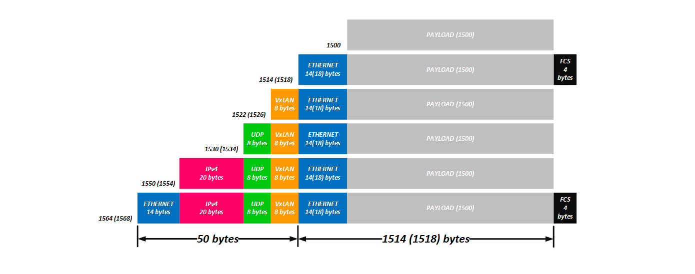
, NVGRE, :
4 ( , ) + 8 (GRE) + 20 (IPv4) + 14 (L2) = 46
VPLS:
4 ( MPLS ) + 4 ( MPLS ) + 14 (L2 ) = 22 (26 ).
FRR , , BGP-LU , : «, »
, 64- , , 4000-9000 — , .
, , VxLAN L2 ( , ):
1. STP;
2. ;
3. L2 (4K vs 16M);
4. (ECMP);
5. L2 ;
6. ( — switchport trunk add — , ) — VxLAN VTEP.
, .
, JunOS? , , . , , . , ? .
.
:
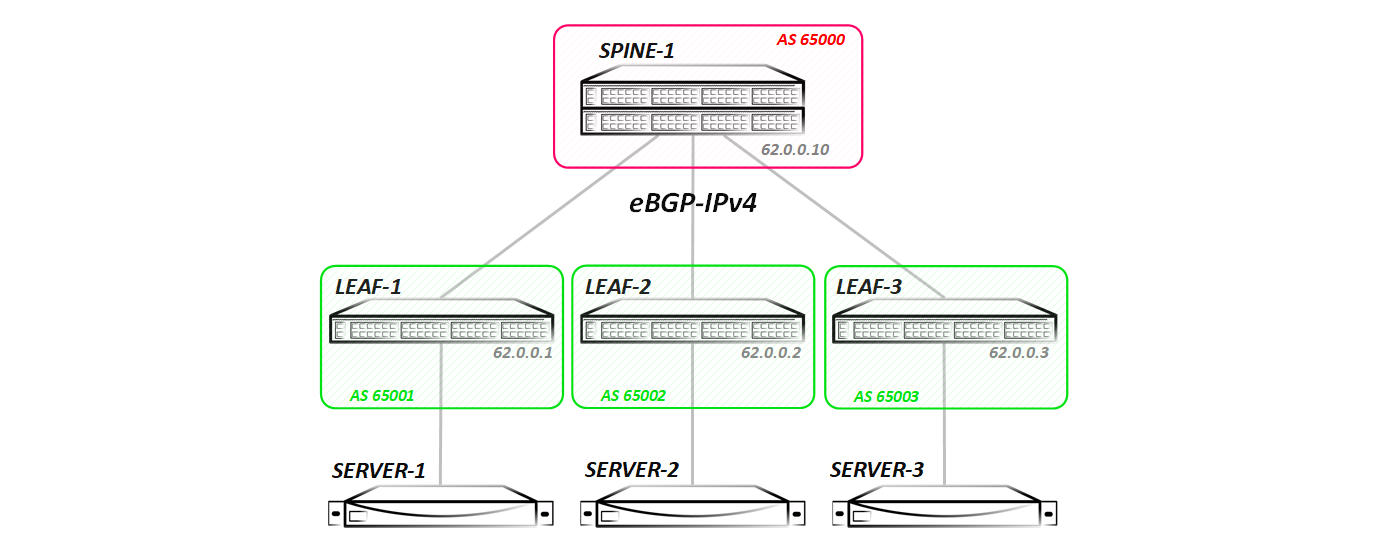
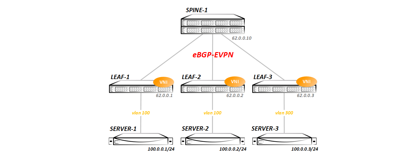
— Spine Leaf-. ( ECMP ), , .
Spine lldp Leaf-:
Spine-1#show lldp neighbors Last table change time : 0:09:43 ago Number of table inserts : 3 Number of table deletes : 0 Number of table drops : 0 Number of table age-outs : 0 Port Neighbor Device ID Neighbor Port ID TTL Et1 Leaf-1 Ethernet1 120 Et2 Leaf-2 Ethernet1 120 Et3 Leaf-3 Ethernet1 120 IGP in its usual form - I did not launch ISIS / OSPF / EIGRP, BGP was used for this purpose - between the Spine and Leaf nodes the eBGP ipv4 sessions are stretched:
Spine-1#show ip bgp summary BGP summary information for VRF default Router identifier 62.0.0.10, local AS number 65000 Neighbor Status Codes: m - Under maintenance Neighbor V AS MsgRcvd MsgSent InQ OutQ Up/Down State PfxRcd PfxAcc 10.0.1.1 4 65001 14 16 0 0 00:09:23 Estab 3 3 10.0.2.1 4 65002 14 16 0 0 00:09:21 Estab 3 3 10.0.3.1 4 65003 14 16 0 0 00:09:19 Estab 3 3 Redistribution of all connected networks is included in BGP (in general, only Lupbacks are needed for VxLAN operation, but I announced everything in order to test routing later). In the future, we will change configurations - add new address families, launch multicast, and so on. Each test will start with the clean topology presented above (all configs that will be made in the previous test will be deleted, so that we can understand what we are running ).
Well, let's start with the banal:
Static (Unicast) VxLAN
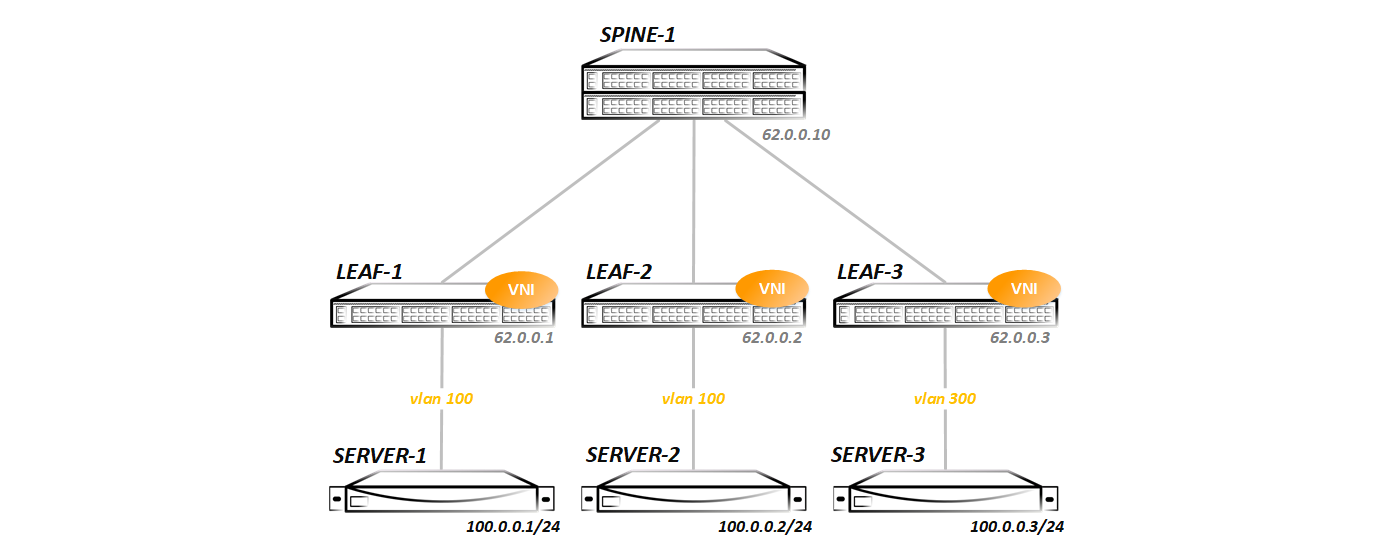
We go in order. Create vlan 100 and enable it on the interface towards the server:
vlan 100 name VNI-1 ! interface Ethernet5 description Server-1 switchport trunk allowed vlan 100 switchport mode trunk Now we need to associate vlan 100 with some vni (no matter what, I chose vni 100 for a long time - you can take any, at least 1 at least 16 million - it does not matter). To do this, create a virtual interface vxlan1:
interface Vxlan1 vxlan source-interface Loopback0 vxlan udp-port 4789 vxlan vlan 100 vni 100 vxlan vlan 100 flood vtep 62.0.0.2 62.0.0.3 vxlan 1 is a tunnel interface that is designed to heat VxLAN tunnels. On Cisco, a similar interface is called nve (network virtualized interface), on Junos - vtep (there is no need to decrypt, thinking), but as you understand, the name bears only a semantic load - the principle of operation does not change from this.
In the configuration of the vxlan interface, we specify which vlan to which vni mappits:
vxlan vlan 100 vni 100 In our case, vlan 100 in VNI 100.
Since we have a static VxLAN, we need to specify all the remote VTEPs, as can be seen in the last line of the vxlan interface config:
vxlan vlan 100 flood vtep 62.0.0.2 62.0.0.3 The diagram shows that in the direction of Server-3, not vlan 100, but vlan 300 is used. Therefore, on Leaf-3, the config is somewhat different:
vlan 300 name VNI-1 ! interface Ethernet5 description Server-1 switchport trunk allowed vlan 300 switchport mode trunk ! interface Vxlan1 vxlan source-interface Loopback0 vxlan udp-port 4789 vxlan vlan 300 vni 100 vxlan vlan 300 flood vtep 62.0.0.1 62.0.0.2 Actually, that's all. Next, check that everything started.
At the moment everything is calm - there was no traffic exchange between the hosts, as evidenced by the lack of poppies in the forwarding table:
Leaf-1#show mac address-table vlan 100 unicast Mac Address Table ------------------------------------------------------------------ Vlan Mac Address Type Ports Moves Last Move ---- ----------- ---- ----- ----- --------- Total Mac Addresses for this criterion: 0 Although all the vteps are statically registered by us:
Leaf-1#show vxlan flood vtep VXLAN Flood VTEP Table -------------------------------------------------------------------------------- VLANS Ip Address ----------------------------- ------------------------------------------------ 100 62.0.0.2 62.0.0.3 but the switch still does not see them, since the exchange has not yet been:
Leaf-1#show vxlan vtep Remote VTEPS for Vxlan1: Total number of remote VTEPS: 0 Here, the behavior of different vendors is different - Nexus or QFX will immediately show you that they see remote VTEP, if they are available over IP. Arista will show us the presence of remote VTEP only after any exchange has been made.
So, we have the following summary information on the VNI configured by us (we have it alone):
Leaf-1#show interfaces vxlan 1 Vxlan1 is up, line protocol is up (connected) Hardware is Vxlan Source interface is Loopback0 and is active with 62.0.0.1 Replication/Flood Mode is headend with Flood List Source: CLI Remote MAC learning via Datapath Static VLAN to VNI mapping is [100, 100] Note: All Dynamic VLANs used by VCS are internal VLANs. Use 'show vxlan vni' for details. Static VRF to VNI mapping is not configured Headend replication flood vtep list is: 100 62.0.0.3 62.0.0.2 What can we actually say about this conclusion? We use loopback0 with address 62.0.0.1 as a source for vxlan tunnels, flood frames occur according to the list of remote VTEPs specified in the CLI, vlan 100 is statically mapped to the VNI 100, and at the end the list of VTEPs we have configured.
On Leaf-2, everything is practically the same (only the list of peers is different, which is logical), and on Leaf-3 there are more changes, as we have already seen, therefore I will give a conclusion from it. As you can see, on Leaf-3 vlan 300 mappits into the same vni 100:
Leaf-3#show vxlan vni 100 VNI to VLAN Mapping for Vxlan1 VNI VLAN Source Interface 802.1Q Tag --------- ---------- ------------ --------------- ---------- 100 300 static Ethernet5 300 Note: * indicates a Dynamic VLAN Leaf-3#show interfaces vxlan 1 Vxlan1 is up, line protocol is up (connected) Hardware is Vxlan Source interface is Loopback0 and is active with 62.0.0.3 Replication/Flood Mode is headend with Flood List Source: CLI Remote MAC learning via Datapath Static VLAN to VNI mapping is [300, 100] Note: All Dynamic VLANs used by VCS are internal VLANs. Use 'show vxlan vni' for details. Static VRF to VNI mapping is not configured Headend replication flood vtep list is: 300 62.0.0.1 62.0.0.3 Now we’ll run the ping between the servers and see if the circuit will take off or not:
bormoglotx@ToR> ping logical-system Server-1 source 100.0.0.1 100.0.0.2 rapid PING 100.0.0.2 (100.0.0.2): 56 data bytes !!!!! --- 100.0.0.2 ping statistics --- 5 packets transmitted, 5 packets received, 0% packet loss round-trip min/avg/max/stddev = 59.807/119.973/338.390/109.381 ms bormoglotx@ToR> ping logical-system Server-1 source 100.0.0.1 100.0.0.3 rapid PING 100.0.0.3 (100.0.0.3): 56 data bytes !!!!! --- 100.0.0.3 ping statistics --- 5 packets transmitted, 5 packets received, 0% packet loss round-trip min/avg/max/stddev = 64.941/89.089/157.432/35.149 ms Ping pass - there is connectivity through the tunnels. Let's look at the mac address table on the switches:
Leaf-1#show vxlan address-table dynamic vlan 100 Vxlan Mac Address Table ---------------------------------------------------------------------- VLAN Mac Address Type Prt VTEP Moves Last Move ---- ----------- ---- --- ---- ----- --------- 100 0005.8671.1e02 DYNAMIC Vx1 62.0.0.2 1 0:00:36 ago 100 0005.8671.1e03 DYNAMIC Vx1 62.0.0.3 1 0:00:32 ago Total Remote Mac Addresses for this criterion: 2 Two mac addresses are learned dynamically and are visible through the tunnel interface, or to be more precise, through the VxLAN tunnel to Leaf-2 and Leaf-3.
The very same table poppy addresses has the following form:
Leaf-1#show mac address-table vlan 100 unicast Mac Address Table ------------------------------------------------------------------ Vlan Mac Address Type Ports Moves Last Move ---- ----------- ---- ----- ----- --------- 100 0005.8671.1e01 DYNAMIC Et5 1 0:00:54 ago 100 0005.8671.1e02 DYNAMIC Vx1 1 0:00:54 ago 100 0005.8671.1e03 DYNAMIC Vx1 1 0:00:50 ago Total Mac Addresses for this criterion: 3 In both cases, you see timers. After a certain time (the default is 300 seconds of inactivity), the poppy will be deleted - everything is standard here.
After the traffic exchange occurred, Leaf-1 found two neighbors:
Leaf-1#show vxlan vtep Remote VTEPS for Vxlan1: 62.0.0.2 62.0.0.3 Total number of remote VTEPS: 2 But Leaf-3 (as well as Leaf-2) sees only one neybor:
Leaf-3#show vxlan vtep Remote VTEPS for Vxlan1: 62.0.0.1 Total number of remote VTEPS: 1 This is logical and normal, since there was no traffic exchange between server 2 and 3.
Now let's see how it will look when removing the dump on the link between Leaf-1 and Spine-1.
The whole exchange is as follows:
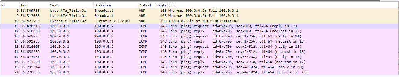
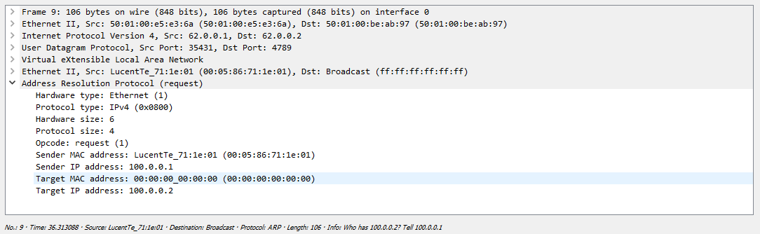
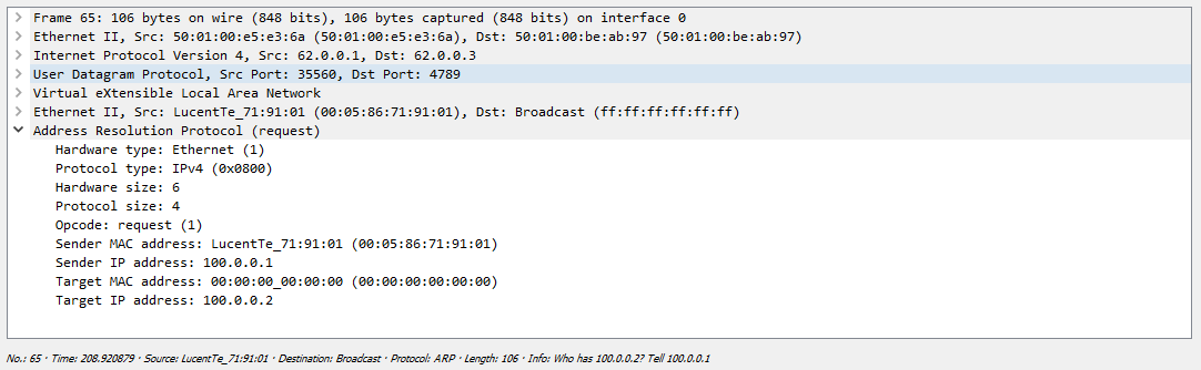
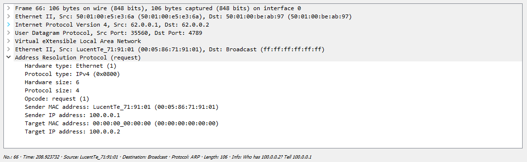
First, the Server forms an ARP request that the switch must send to all remote VTEPs. As we found out earlier, replication occurs on the outgoing node with the further distribution of the package by unicast:

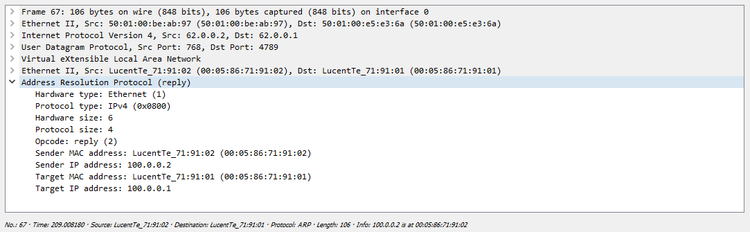
One of their servers just drops the received packet, since this request is not addressed to it, but the second server responds safely:

After that, both servers know each other’s mac addresses and can start exchanging traffic, in our case ICMP:

Now we will make a gateway for access to the external network with VRRP:
Leaf-1#show running-config interfaces vlan 100 interface Vlan100 ip address 100.0.0.252/24 vrrp 100 priority 128 vrrp 100 authentication text vlan100 vrrp 100 ip 100.0.0.254 Leaf-2#show running-config interfaces vlan 100 interface Vlan100 ip address 100.0.0.253/24 vrrp 100 priority 64 vrrp 100 authentication text vlan100 vrrp 100 ip 100.0.0.254 Leaf-1#show vrrp group 100 interface vlan 100 Vlan100 - Group 100 VRF is default VRRP Version 2 State is Master Virtual IPv4 address is 100.0.0.254 Virtual MAC address is 0000.5e00.0164 Mac Address Advertisement interval is 30s VRRP Advertisement interval is 1s Preemption is enabled Preemption delay is 0s Preemption reload delay is 0s Priority is 128 Authentication text, string "vlan100" Master Router is 100.0.0.252 (local), priority is 128 Master Advertisement interval is 1s Skew time is 0.500s Master Down interval is 3.500s Now run ping server 3 to the gateway:
bormoglotx@ToR> ping logical-system Server-3 source 100.0.0.3 100.0.0.254 rapid PING 100.0.0.254 (100.0.0.254): 56 data bytes !!!!! --- 100.0.0.254 ping statistics --- 5 packets transmitted, 5 packets received, 0% packet loss round-trip min/avg/max/stddev = 56.915/75.978/134.126/29.286 ms Gateway is available. Since we have a vlan interface in grt, then having announced this address via BGP, we can reach other networks, for example, our own Leaf-3 loopback:
bormoglotx@ToR> ping logical-system Server-3 source 100.0.0.3 62.0.0.3 rapid PING 62.0.0.3 (62.0.0.3): 56 data bytes !!!!! --- 62.0.0.3 ping statistics --- 5 packets transmitted, 5 packets received, 0% packet loss round-trip min/avg/max/stddev = 93.210/111.745/138.930/16.970 ms The traffic path in this scenario is as follows: a packet from the server on the default route falls on Leaf-3. Since the MAC address of the gateway, which is specified as the destination address, Leaf-3 knows through the VxLAN tunnel to Leaf-1, the packet through this tunnel flies to Leaf-1. Further, Leaf-1 decapsulates the packet, and sees that the destination address is 62.0.0.3, the route to which it is known in grt through bgp. Next, the packet is routed back to Leaf-3. The response from the loopback Leaf-3 is returned in the same way.
As you can see, the VxLAN technology, and especially in the version we have considered —Static (Unicast) VxLAN — is as simple as a boot and as reliable as a Kalashnikov assault rifle. Well, what is there to break as a matter of fact?
For example, here are the configs from Cisco and Juniper:
On the Cisco Nexus, everything is more or less similar to the Arista configuration - in any case, the approach is the same.
We create nve interface (analog vxlan) and the vlan we need:
vlan 100 name VNI-100 vn-segment 100 interface nve1 no shutdown source-interface loopback0 member vni 100 ingress-replication protocol static peer-ip 62.0.0.2 peer-ip 62.0.0.3 Further we allow this vlan towards the client and everything is ready. Naturally, since this Nexus does not forget to include the features we need:
interface Ethernet1/2 description Server-1 | LS-3 switchport mode trunk switchport trunk allowed vlan 100 feature bgp feature vn-segment-vlan-based feature lldp feature nv overlay On Juniper QFX, everything is a little different (well, it's a juniper). In the switch-options hierarchy, we specify the source for the VxLAN tunnel and the addresses of the remote VTEPs:
switch-options { vtep-source-interface lo0.0; remote-vtep-list [ 62.0.0.2 62.0.0.3 ]; } vlans { VLAN400 { vlan-id 400; vxlan { vni 16000100; ingress-node-replication; } } } Further we allow this vlan towards the client and everything is ready.
I think we figured it out. Now let's move on to the second option - we will use multicast to automatically search for neighbors and replicate BUM traffic.
Multicast VxLAN
As you might guess, first we need to run PIM. We will use Spine as RP, since it has an ideal location in the topology for performing this function. I will not show off and set up a static RP, and I have only one spine:

ip pim rp-address 62.0.0.10 ! interface Ethernet1 ip pim sparse-mode Since we deleted the entire config we made in the first test, we need to create the required vlan again (100 vlan on Leaf-1/2 and 300 on Leaf-3), and allow them to the server (I will not show the config , you already saw it).
Now we create the vxlan interface:
interface Vxlan1 vxlan multicast-group 230.0.0.100 vxlan source-interface Loopback0 vxlan udp-port 4789 vxlan vlan 100 vni 100 Like last time, vlan 100 corresponds to vni 100 (on Leaf-3, vlan 300 corresponds to vni 100). Now we need to associate vni 100 with mgroup 230.0.0.100. Such a chain was obtained - vlan 100 >> vni 100 >>> mgroup 230.0.0.100.
That's the whole configuration. Check that our configuration will take off. Let's see if a neighborhood with all leaf has climbed to RP:
Spine-1#show ip pim neighbor PIM Neighbor Table Neighbor Address Interface Uptime Expires Mode 10.0.1.1 Ethernet1 00:03:53 00:01:20 sparse 10.0.2.1 Ethernet2 00:03:55 00:01:19 sparse 10.0.3.1 Ethernet3 00:03:52 00:01:21 sparse Great, the Nybora are visible. We look at the summary information on vxlan:
Leaf-1#show interfaces vxlan 1 Vxlan1 is up, line protocol is up (connected) Hardware is Vxlan Source interface is Loopback0 and is active with 62.0.0.1 Replication/Flood Mode is multicast Remote MAC learning via Datapath Static VLAN to VNI mapping is [100, 100] Note: All Dynamic VLANs used by VCS are internal VLANs. Use 'show vxlan vni' for details. Static VRF to VNI mapping is not configured Multicast group address is 230.0.0.100 Here, the replication method and the flood are indicated - multicast, and instead of a sheet listing all remote VTEPs - only the multicast group. For Leaf-3, everything is the same, adjusted for the Vlan number:
Leaf-3#show vxlan vtep Remote VTEPS for Vxlan1: Total number of remote VTEPS: 0 Leaf-3#show interfaces vxlan 1 Vxlan1 is up, line protocol is up (connected) Hardware is Vxlan Source interface is Loopback0 and is active with 62.0.0.3 Replication/Flood Mode is multicast Remote MAC learning via Datapath Static VLAN to VNI mapping is [300, 100] Note: All Dynamic VLANs used by VCS are internal VLANs. Use 'show vxlan vni' for details. Static VRF to VNI mapping is not configured Multicast group address is 230.0.0.100 Since we already know how VxLAN should work through multicast, then according to the rules, after we configured the vxlan interface and added the vlan << >> VNI association, Leafs should join the 230.0.0.100 group:
Leaf-1#show ip mroute PIM Bidirectional Mode Multicast Routing Table RPF route: U - From unicast routing table M - From multicast routing table PIM Sparse Mode Multicast Routing Table Flags: E - Entry forwarding on the RPT, J - Joining to the SPT R - RPT bit is set, S - SPT bit is set, L - Source is attached W - Wildcard entry, X - External component interest I - SG Include Join alert rcvd, P - (*,G) Programmed in hardware H - Joining SPT due to policy, D - Joining SPT due to protocol Z - Entry marked for deletion, C - Learned from a DR via a register A - Learned via Anycast RP Router, M - Learned via MSDP N - May notify MSDP, K - Keepalive timer not running T - Switching Incoming Interface, B - Learned via Border Router RPF route: U - From unicast routing table M - From multicast routing table 230.0.0.100 0.0.0.0, 0:00:05, RP 62.0.0.10, flags: W Incoming interface: Ethernet1 RPF route: [U] 62.0.0.10/32 [200/0] via 10.0.1.0 Outgoing interface list: Loopback0 We see the record (*, G) - that is, Leaf-1 wants to receive multicast traffic of the group 230.0.0.100 and no matter who will be the source for this group. Since there was no traffic exchange, there are no poppies in the forwading table on the switch either:
Leaf-1#show vxlan address-table Vxlan Mac Address Table ---------------------------------------------------------------------- VLAN Mac Address Type Prt VTEP Moves Last Move ---- ----------- ---- --- ---- ----- --------- Total Remote Mac Addresses for this criterion: 0 As well as there are no known remote VTEPs:
Leaf-1#show vxlan vtep Remote VTEPS for Vxlan1: Total number of remote VTEPS: 0 Let's start ping between servers and check the fact of connectivity, and, accordingly, the presence of poppies in VTEP tables:
bormoglotx@ToR> ping logical-system Server-1 100.0.0.2 rapid PING 100.0.0.2 (100.0.0.2): 56 data bytes !!!!! --- 100.0.0.2 ping statistics --- 5 packets transmitted, 5 packets received, 0% packet loss round-trip min/avg/max/stddev = 57.521/69.366/82.147/10.469 ms bormoglotx@ToR> ping logical-system Server-1 100.0.0.3 rapid PING 100.0.0.3 (100.0.0.3): 56 data bytes !!!!! --- 100.0.0.3 ping statistics --- 5 packets transmitted, 5 packets received, 0% packet loss round-trip min/avg/max/stddev = 59.762/81.369/164.374/41.505 ms There is a connection, and judging by the conclusion below, Leaf-1 found two remote VTEPs:
Leaf-1#show vxlan vtep Remote VTEPS for Vxlan1: 62.0.0.2 62.0.0.3 Total number of remote VTEPS: 2 It is logical that the addresses of servers 2 and 3 will be visible through the vxlan tunnel:
Leaf-1#show vxlan address-table vlan 100 Vxlan Mac Address Table ---------------------------------------------------------------------- VLAN Mac Address Type Prt VTEP Moves Last Move ---- ----------- ---- --- ---- ----- --------- 100 0005.8671.1e02 DYNAMIC Vx1 62.0.0.2 1 0:00:47 ago 100 0005.8671.1e03 DYNAMIC Vx1 62.0.0.3 1 0:00:41 ago Total Remote Mac Addresses for this criterion: 2 But we have already seen everything described above in the past test - where are the differences? Differences further. Since Leaf-1 sent traffic to the group address 230.0.0.100, we should see that this switch became the source for this group:
Spine-1#show ip pim upstream joins Neighbor address: 10.0.1.1 Via interface: Ethernet1 (10.0.1.0) Group: 230.0.0.100 Joins: 62.0.0.1/32 SPT Prunes: No prunes included Now let's move to Leaf-3, and see which groups this switch listens on:
Leaf-3#show ip mroute PIM Bidirectional Mode Multicast Routing Table RPF route: U - From unicast routing table M - From multicast routing table PIM Sparse Mode Multicast Routing Table Flags: E - Entry forwarding on the RPT, J - Joining to the SPT R - RPT bit is set, S - SPT bit is set, L - Source is attached W - Wildcard entry, X - External component interest I - SG Include Join alert rcvd, P - (*,G) Programmed in hardware H - Joining SPT due to policy, D - Joining SPT due to protocol Z - Entry marked for deletion, C - Learned from a DR via a register A - Learned via Anycast RP Router, M - Learned via MSDP N - May notify MSDP, K - Keepalive timer not running T - Switching Incoming Interface, B - Learned via Border Router RPF route: U - From unicast routing table M - From multicast routing table 230.0.0.100 0.0.0.0, 0:03:48, RP 62.0.0.10, flags: W Incoming interface: Ethernet1 RPF route: [U] 62.0.0.10/32 [200/0] via 10.0.3.0 Outgoing interface list: Loopback0 62.0.0.1, 0:01:50, flags: S Incoming interface: Ethernet1 RPF route: [U] 62.0.0.1/32 [200/0] via 10.0.3.0 Outgoing interface list: Loopback0 Here we see a record of the type (*, G) that was previously (it tells us that the switch listens to the group 230.0.0.100 and does not care who the source is). But the second entry already has the form (S, G), which tells us that the switch is listening to the group 230.0.0.100 with the address sorsa 62.0.0.1.
Now we’ll see a dump to see the whole exchange, so to speak, live:
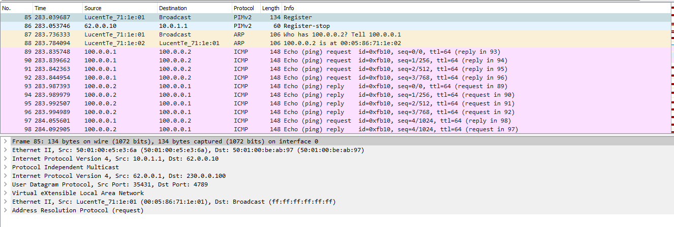
The whole exchange looks a little different than in the first case. First, a message is sent to the multicast group address:

In the dump, the PIM Register and Register-stop messages are clearly visible - that is, the multicast operation is in its pure form.
Next we see the answer from the remote server, but unicast:
Well, after what the traffic exchange follows:

Now we will add another Server-4 server to the schema, connect it to Leaf-3 and place it on the VNI 200:
The configuration on Leaf-3 has changed somewhat:
Leaf-3(config-if-Vx1)#show active interface Vxlan1 vxlan multicast-group 230.0.0.100 vxlan source-interface Loopback0 vxlan udp-port 4789 vxlan vlan 200 vni 200 vxlan vlan 300 vni 100 I want to note that both VNI will use the same multicast group.
Now, when trying to view information on the VxLAN interface, we see that we now have two VNIs:
Leaf-3#show interfaces vxlan 1 Vxlan1 is up, line protocol is up (connected) Hardware is Vxlan Source interface is Loopback0 and is active with 62.0.0.3 Replication/Flood Mode is multicast Remote MAC learning via Datapath Static VLAN to VNI mapping is [200, 200] [300, 100] Note: All Dynamic VLANs used by VCS are internal VLANs. Use 'show vxlan vni' for details. Static VRF to VNI mapping is not configured Multicast group address is 230.0.0.100 Vlan 200 is mapped in VNI 200, vlan 300 in VNI 100. They are looking at the same port:
Leaf-3#show vxlan vni VNI to VLAN Mapping for Vxlan1 VNI VLAN Source Interface 802.1Q Tag --------- ---------- ------------ --------------- ---------- 100 300 static Ethernet5 300 200 200 static Ethernet5 200 Note: * indicates a Dynamic VLAN Next, create L3 interfaces. On Leaf-1/2 we will make the vlan 100 interface with vrrp (as in the last test, I will not re-configure), and on Leaf-3 we will create a gate for the VNI 200:
Leaf-3#show running-config interfaces vlan 200 interface Vlan200 ip address 200.0.0.254/24 Leaf-3#show vlan id 200 VLAN Name Status Ports ----- -------------------------------- --------- ------------------------------- 200 VNI-200 active Cpu, Et5, Vx1 As a result, our scheme acquired the following form:

Now let's check if routing between VNI works:
bormoglotx@ToR> ping logical-system Server-4 source 200.0.0.3 100.0.0.3 PING 100.0.0.3 (100.0.0.3): 56 data bytes 64 bytes from 100.0.0.3: icmp_seq=0 ttl=61 time=155.736 ms 64 bytes from 100.0.0.3: icmp_seq=1 ttl=61 time=117.702 ms 64 bytes from 100.0.0.3: icmp_seq=2 ttl=61 time=120.800 ms 64 bytes from 100.0.0.3: icmp_seq=3 ttl=61 time=127.033 ms ^C --- 100.0.0.3 ping statistics --- 4 packets transmitted, 4 packets received, 0% packet loss round-trip min/avg/max/stddev = 117.702/130.318/155.736/15.055 ms The traffic path at the moment is the same - from Server-3 traffic flies along the default route to the mac address of the default gateway, which is on Leaf-3. The switch, having received the packet, decapsulates it, and sees that it is intended for itself (vlan interface), then IP lookup occurs. Since the host 100.0.0.3 lives on the network 100.0.0.0/24, the traffic is sent to Leaf-1, since the destination network is terminated there (VRRP Master lives on Leaf-1). Over the IP network via Spine, the packet reaches Leaf-1. The switch, accepting an IP packet (not a VxLAN but a pure IP), looks at the destination address and realizes that it sees it through the VxLAN tunnel to Leaf-3. The packet is encapsulated in the VxLAN and sent to Leaf-3. Leaf-3, receives the packet, decapsulates it, sees that the destination address is 100.0.0.3, which is connected to it via the eth5 interface, hangs a vlan tag and sends it to the server. Here we have such an optimal routing, we have two servers that live on the same interface and communicate through the entire IP factory.
As in the previous section for an example configuration of a similar service with Cisco and Juniper:
On the Nexus, everything again looks like Arista. We also create the necessary vlan and associate it with VNI:
vlan 100 name VNI-16000100 vn-segment 16000100 And in the nve interface we indicate which multicast group should be tied to vni
interface nve1 no shutdown source-interface loopback0 overlay-encapsulation vxlan member vni 16000100 mcast-group 225.0.0.100 Naturally, we include the PIM feature and the PIM itself on the right interfaces. Next, the vlan is prescribed in the direction of the client and everything should take off.
interface Ethernet1/2 description Server-1 | LS-3 switchport mode trunk switchport trunk allowed vlan 100 On Juniper QFX, you first need to enable pim on the right interfaces (including Lo0), as well as enable tunnel services on some of the FPC (necessary for PIM to work):
pim { rp { static { address 62.0.0.10; } } interface xe-0/0/1.0 { mode sparse; } interface lo0.0 { mode sparse; } interface xe-0/0/2.0 { mode sparse; chassis { fpc 0 { pic 0 { tunnel-services { bandwidth 40g; } } } } Further, the configuration looks like this:
{master:0}[edit] bormoglotx@LEAF-101# show switch-options vtep-source-interface lo0.0; {master:0}[edit] bormoglotx@LEAF-101# show vlans BRIDGE-4093 { vlan-id 4093; vxlan { vni 4093; multicast-group 230.0.40.93; } } Further we allow this vlan towards the client.
I think we figured it out, so we move on.
EVPN / VxLAN
Forgot your previous configuration and do it all over again:
Create vlan 100 and enable it on the interface towards the server:
Leaf-1#show running-config section vlan 100 vlan 100 name VNI-1 ! interface Ethernet5 description Server-1 switchport trunk allowed vlan 100 switchport mode trunk Now we create the vxlan interface again, but now we only need to specify the outgoing interface for the vxlna tunnel (usually one of the loopbacks) and associate vlan 100 with vni 100:
interface Vxlan1 vxlan source-interface Loopback0 vxlan udp-port 4789 vxlan vlan 100 vni 100 And then go to bgp. Add the ability to forward extended communities, include the evpn address family, and add a neybor, which is Spine-1:
router bgp 65001 neighbor 10.0.1.0 remote-as 65000 neighbor 10.0.1.0 description Spine-1 neighbor 10.0.1.0 soft-reconfiguration inbound all neighbor 10.0.1.0 send-community extended neighbor 10.0.1.0 maximum-routes 100 redistribute connected ! vlan 100 rd 65001:100 route-target import 65002:100 route-target import 65003:100 route-target export 65001:100 redistribute learned ! address-family evpn neighbor 10.0.1.0 activate ! address-family ipv4 neighbor 10.0.1.0 activate evpn (ibgp/ebgp multihop), ebgp, , — — . , . — ( ).
bgp vlan. evpn (EVI). — rd ( ), rt — VTEP . — Leaf-2, — Leaf-3. redistribute learned , data plane, bgp. L3 . arista, Juniper .
. , , Leaf-3 vni 100 vlan 300.
:
Leaf-1#show interfaces vxlan 1 Vxlan1 is up, line protocol is up (connected) Hardware is Vxlan Source interface is Loopback0 and is active with 62.0.0.1 Replication/Flood Mode is headend with Flood List Source: EVPN Remote MAC learning via EVPN Static VLAN to VNI mapping is [100, 100] Note: All Dynamic VLANs used by VCS are internal VLANs. Use 'show vxlan vni' for details. Static VRF to VNI mapping is not configured Headend replication flood vtep list is: 100 62.0.0.3 62.0.0.2 , — loopback0 62.0.0.1, , EVPN. Vlan 100 VNI 100. VTEP-, EVPN. VTEP:
Leaf-1#show vxlan vtep Remote VTEPS for Vxlan1: 62.0.0.2 62.0.0.3 Total number of remote VTEPS: 2 , Leaf-2/3 VxLAN ? EVPN 3:
Leaf-1#show bgp evpn route-type ? auto-discovery Filter by Ethernet Auto-Discovery (AD) route (Type 1) ethernet-segment Filter by Ethernet Segment Route (Type 4) imet Filter by Inclusive Multicast Ethernet Tag Route (Type 3) <<<< mac-ip Filter by MAC/IP advertisement route (Type 2) — , — Inclusive Multicast Ethernet Tag VTEP-:
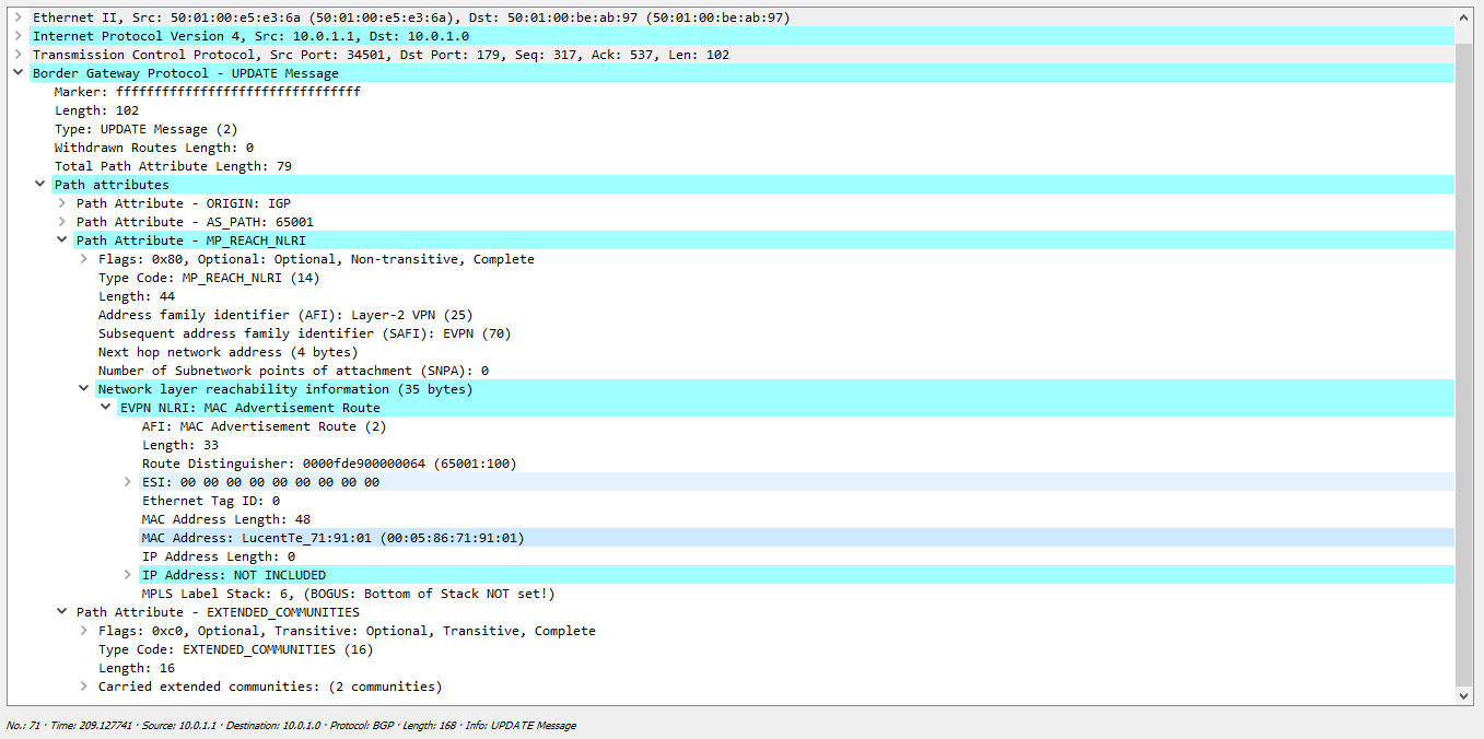
Leaf-1#show bgp evpn route-type imet BGP routing table information for VRF default Router identifier 62.0.0.1, local AS number 65001 Route status codes: s - suppressed, * - valid, > - active, # - not installed, E - ECMP head, e - ECMP S - Stale, c - Contributing to ECMP, b - backup % - Pending BGP convergence Origin codes: i - IGP, e - EGP, ? - incomplete AS Path Attributes: Or-ID - Originator ID, C-LST - Cluster List, LL Nexthop - Link Local Nexthop Network Next Hop Metric LocPref Weight Path * > RD: 65001:100 imet 62.0.0.1 - - - 0 i * > RD: 65002:100 imet 62.0.0.2 62.0.0.2 - 100 0 65000 65002 i * > RD: 65003:100 imet 62.0.0.3 62.0.0.3 - 100 0 65000 65003 i :
Leaf-1#show bgp evpn route-type imet vni 100 next-hop 62.0.0.2 detail BGP routing table information for VRF default Router identifier 62.0.0.1, local AS number 65001 BGP routing table entry for imet 62.0.0.2, Route Distinguisher: 65002:100 Paths: 1 available 65000 65002 62.0.0.2 from 10.0.1.0 (62.0.0.10) Origin IGP, metric -, localpref 100, weight 0, valid, external, best Extended Community: Route-Target-AS:65002:100 TunnelEncap:tunnelTypeVxlan VNI: 100 AS-PATH ( ebgp overlay , ), next-hop ( , ebgp Spine next-hop-, B ), VxLAN ( : TunnelEncap:tunnelTypeVxlan) VNI 100.
( VNI ). :
Leaf-1#show mac address-table unicast vlan 100 Mac Address Table ------------------------------------------------------------------ Vlan Mac Address Type Ports Moves Last Move ---- ----------- ---- ----- ----- --------- Total Mac Addresses for this criterion: 0 :
bormoglotx@ToR> ping logical-system Server-1 100.0.0.2 rapid PING 100.0.0.2 (100.0.0.2): 56 data bytes !!!!! --- 100.0.0.2 ping statistics --- 5 packets transmitted, 5 packets received, 0% packet loss round-trip min/avg/max/stddev = 72.731/94.632/115.048/13.476 ms bormoglotx@ToR> ping logical-system Server-1 100.0.0.3 rapid PING 100.0.0.3 (100.0.0.3): 56 data bytes !!!!! --- 100.0.0.3 ping statistics --- 5 packets transmitted, 5 packets received, 0% packet loss round-trip min/avg/max/stddev = 67.071/99.286/177.772/40.933 ms , . , :
Leaf-1#show mac address-table Mac Address Table ------------------------------------------------------------------ Vlan Mac Address Type Ports Moves Last Move ---- ----------- ---- ----- ----- --------- 100 0005.8671.9101 DYNAMIC Et5 1 0:00:36 ago 100 0005.8671.9102 DYNAMIC Vx1 1 0:00:35 ago 100 0005.8671.9103 DYNAMIC Vx1 1 0:00:19 ago Total Mac Addresses for this criterion: 3 , VxLAN . , :
Leaf-1#show vxlan address-table Vxlan Mac Address Table ---------------------------------------------------------------------- VLAN Mac Address Type Prt VTEP Moves Last Move ---- ----------- ---- --- ---- ----- --------- 100 0005.8671.9102 EVPN Vx1 62.0.0.2 1 0:01:03 ago 100 0005.8671.9103 EVPN Vx1 62.0.0.3 1 0:00:48 ago Total Remote Mac Addresses for this criterion: 2 . EVPN, . , bgp:
Leaf-1#show bgp evpn route-type mac-ip BGP routing table information for VRF default Router identifier 62.0.0.1, local AS number 65001 Route status codes: s - suppressed, * - valid, > - active, # - not installed, E - ECMP head, e - ECMP S - Stale, c - Contributing to ECMP, b - backup % - Pending BGP convergence Origin codes: i - IGP, e - EGP, ? - incomplete AS Path Attributes: Or-ID - Originator ID, C-LST - Cluster List, LL Nexthop - Link Local Nexthop Network Next Hop Metric LocPref Weight Path * > RD: 65001:100 mac-ip 0005.8671.9101 - - - 0 i * > RD: 65001:100 mac-ip 0005.8671.9101 100.0.0.1 - - - 0 i * > RD: 65002:100 mac-ip 0005.8671.9102 62.0.0.2 - 100 0 65000 65002 i * > RD: 65003:100 mac-ip 0005.8671.9103 62.0.0.3 - 100 0 65000 65003 i — AS Path, .
:

, VTEP- IM , , BGP ( - VNI ). :
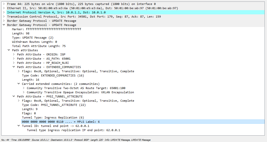
, c VNI 100 (, 6), , 62.0.0.1 VxLAN.
. - , , VxLAN, (, , ):
ARP :
BGP Upgrade . , - mac data plane, BGP mac :
— . data-plane , Server-1 c Server-2 Server-3, Leaf-2 Leaf-3 — , Leaf-1. 2 3 , . , 2 3, , Leaf-2 -3. EVPN Leaf-2 Leaf-3 , BGP.
Cisco Juniper:
Cisco Nexus VNI:
vlan 100 name VNI-100 vn-segment 100 nve , , BGP (host-reachability protocol bgp):
interface nve1 no shutdown source-interface loopback0 host-reachability protocol bgp member vni 100 ingress-replication protocol bgp ingress-replication protocol bgp , . VTEP-, BGP.
evpn (EVI):
evpn vni 100 l2 rd 65001:100 route-target import 65001:100 route-target import 65002:100 route-target import 65003:100 route-target export 65001:100 .
Juniper QFX ( bgp ):
:
{master:0} bormoglotx@LEAF-101> show configuration vlans BRIDGE-4093 { vlan-id 4093; vxlan { vni 15000001; ingress-node-replication; } } BRIDGE-4094 { vlan-id 4094; vxlan { vni 16000001; ingress-node-replication; } } switch-options:
{master:0} bormoglotx@LEAF-101> show configuration switch-options vtep-source-interface lo0.0; route-distinguisher 62.0.0.101:1; vrf-import VNI-IMPORT; vrf-target export target:42000:9999; RD RT, VTEP, RT, 1, per-ESI.
, :
bormoglotx@LEAF-101> show configuration policy-options policy-statement VNI-IMPORT term DC-DEFAULT { from { protocol bgp; community DC-DEFAULT-SW; } then accept; } term VNI-16000001 { from { protocol bgp; community VNI16000001; } then accept; } term VNI-15000001 { from { protocol bgp; community VNI15000001; } then accept; } then reject; evpn:
{master:0} bormoglotx@LEAF-101> show configuration protocols evpn encapsulation vxlan; extended-vni-list [ 15000001 16000001 ]; multicast-mode ingress-replication; vni-options { vni 15000001 { vrf-target export target:1500:1; } vni 16000001 { vrf-target export target:1600:1; } } , rt VNI VNI .
.
, , . EVPN/VxLAN multihomig Arista MLAG Nexus vPC, EVPN Juniper QFX.
- // – . Thanks for attention.
Source: https://habr.com/ru/post/344326/
All Articles