How we taught smart socket to measure power
Welcome
We - the company Rubetek, are engaged in developments in the field of solutions for smart home.
In this article we will talk about how, during the development of one of the devices of our Wi-Fi line, we chose a solution for accurate measurement of the power of connected electrical appliances.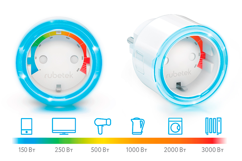
Our Wi-Fi outlet
What kind of device did?
Wi-Fi socket Rubetek is a device designed for remote power management of connected electrical appliances up to 3000 watts. The outlet is controlled by a button located on the case locally (smartphone - WiFi socket, smartphone - WiFi router - Wi-Fi socket) and remotely when the router is connected to the Internet.
The state of the device is changed by the triggering of sensors connected to the outlet of the RF or through the use of pre-configured user scripts.
One of the key functions of the device is monitoring the power consumption of the connected load.
To display the load level of the socket uses an LED indicator that changes the color of the glow in accordance with the power consumed by the load.
The device allows you to connect compatible sensors with the EV1527 protocol (433.92 MHz, ASK) RF sensors (movements, openings, water leaks, gas and smoke leaks) and create scenarios of interaction between the connected devices.
In addition, the smart socket is compatible with the Apple Homekit platform and supports control with Siri voice assistant. Remote control of Homekit via the Internet is possible only with the help of Apple TV, but you can control the voice locally from the iPhone without using Apple TV.
First attempts
At the first stage, the Z-Wave module was selected as the basis for the future outlet (Fig. 2).
According to the terms of reference, the socket had to measure the consumed electricity in single-phase circuits, in the range from 0 W to 3000 W., with an error of no more than 1%.
- To measure the current consumed by the load, and the voltage on the load, we used a circuit consisting of a dual opamp TSV522, a current shunt and a resistive amplifier.
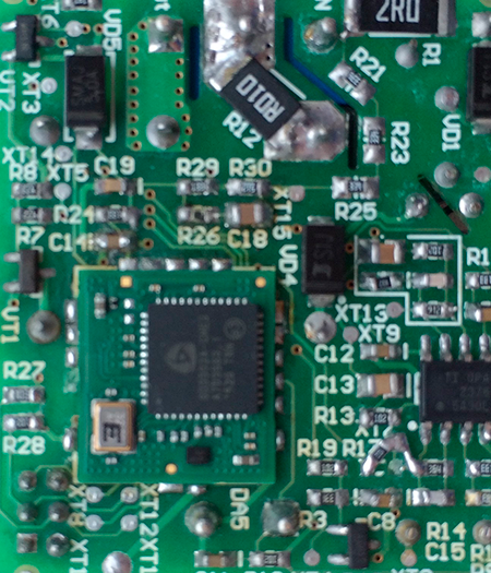
The first prototype on the module Z-Wave
The calculation of the active power consumed by the load was calculated by the formula:
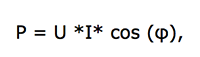
Where:
P - active power consumed by the load
U - effect. load voltage equal to mains voltage
I - effect. load current
φ - phase shift between current and voltage on the load
- The advantages were low input current (1 μA) and low bias voltage (0.8 mV). The input and output signal had a voltage sweep (rail-to-rail).
- The accuracy of measuring the load current with a power consumption of up to 100 W in the range from 0 to 3000 W did not suit us, and to increase it, we used two operational amplifiers operating from a common current shunt and having different gain factors: an amplifier with a large gain factor worked in range from 0 watts to 100 watts, and an amplifier with lower gain worked in the range from 100 watts to 3000 watts.
When developing Wi-Fi sockets, one of the main requirements was the compactness of the product, therefore, we considered the use of several cases of amplifier circuits and ADCs to be irrational. In addition, the analog signal at the output of the amplifiers was very “noisy”, the level of interference did not allow to achieve the specified error in measuring the power consumed by the load. This was especially noticeable on an amplifier operating in the range from 0 W to 100 W. (Fig.3).
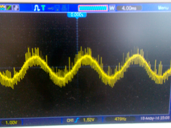
Oscillogram from the current shunt of the Z-Wave ADC module with a power of 10 W load
At this stage, in order to increase the measurement accuracy and increase the degree of integration, it was necessary to find a new solution for implementing the power measurement. It was decided to abandon the Z-Wave module, due to the high cost and poor performance, and OU. The new foundation was the Wi-Fi MCU.
The rejection of Z-Wave in favor of Wi-Fi was due to the obvious advantages of the latter:
the presence of Wi-Fi in any smartphone that allows you to directly control the outlet from the application, the ability to connect to the router for remote control of the outlet from anywhere in the world. This determined the further development of the line of our smart devices.
Looking for a solution
The search for options for the implementation of power measurement led us to specialized measuring RMS chips.
We chose a relatively inexpensive RMS - STPM14A.
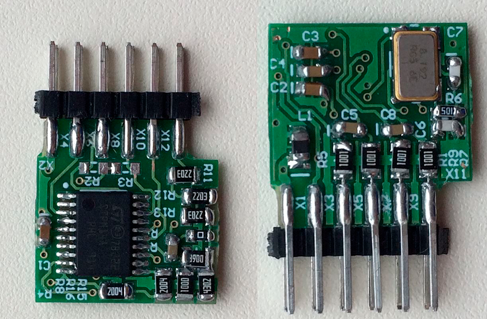
Prototype STPM14A Module
This RMS measures active, reactive and apparent power, effective values of current, voltage and frequency, supports current transformers and shunts, is distinguished by low power consumption, high measurement accuracy, reliability of data transmission and storage. In general, STPM14 suited us in many ways.

Block diagram of STPM14A
But not without its drawbacks.
When using STPM14A, difficulties arose at the data processing stage: this measuring chip did not have a digital output, only a frequency one, which required resources from the Wi-Fi MCU to process the frequency signal. Our Wi-Fi MCU was already loaded with a host of other functions: processing discrete signals, interaction with the server, encryption, timers, scripts. It turned out that the processing of the frequency signal was not possible to implement without consequences for the rest of the functional.
We had to return to the search for alternative solutions also because STPM14A did not have a digital output. After examining several options, we decided to stop on the STPM32 chip. To Wi-Fi MCU STPM32 connected via UART.
STPM32 is a mixed signal processing device. The processor consists of analog and digital blocks.
Analog includes:
- two low-noise amplifiers with programmable gain and low offset;
- four 24-bit delta-sigma second-order ADC;
- two sources of reference voltage based on the forbidden zone with independent temperature compensation;
- low drop voltage regulator;
- dc buffers.
The digital block consists of a cascade of digital filtering, a hardware-based digital signal processor, buffer cascades for input signals, and serial interfaces (UART or SPI).
The measuring chip STPM32 contained two channels for processing analog current and voltage signals, followed by conversion to a digital signal and a high-precision digital signal processor DSP, designed to process digital signals in real time.
The main and most noticeable disadvantage, against the background of all the listed advantages, was that when working with small signals, with the maximum gain (16x), the error in current measurement increased.
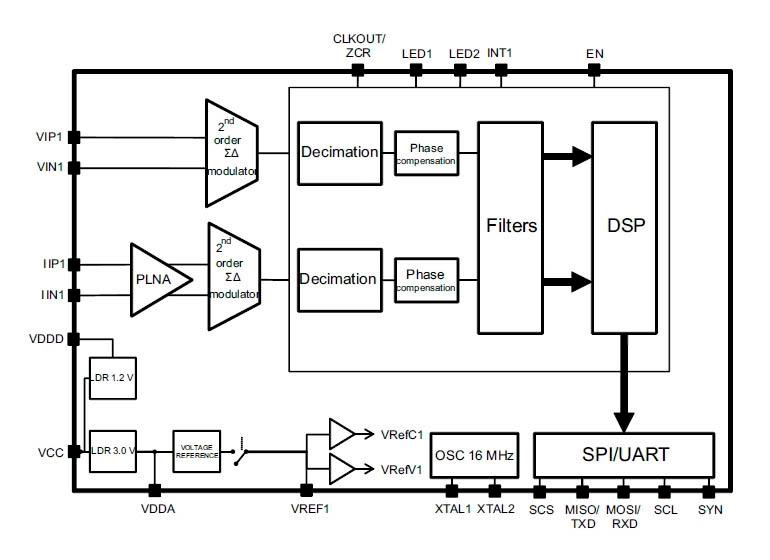
Block diagram of STPM32
How to test?
For testing and testing, we have developed a prototype board.
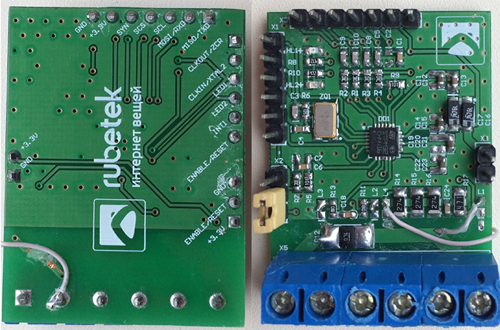
This is how the prototype of power measurement looks like on STPM32
Testing took place at different loads with power from a few watts to 3.5 kW. Incandescent lamps, heating elements (resistive load), fluorescent lamps and power tools (resistive-inductive load), electrical appliances with switching power supplies without a power factor corrector (resistive-capacitive load) were used as the load.
During the prototyping on the debug board, we received positive results, which we were completely satisfied with. STPM32 coped well with the task and could be used in our smart outlet.
Later it turned out that the total measurement error of the device did not correspond to the real readings. We obtained this data by measuring indicators with several household wattmeters of different price categories.
To achieve the specified accuracy of the load power measurement, it was decided to calibrate serial products at the production stage. For this purpose, a special stand was designed and manufactured (Fig. 6), which contained a separate one, calibrated using the STPM32 standard power meter.
The stand had a galvanic isolation from the network in order to ensure electrical safety.
Each product after assembly was connected to the contact device of the stand.
The operator ran a program that provided electrical testing of the outlet for the absence of errors during installation and firmware. In addition, the main outlet functionality was tested and STPM32 calibration was performed.
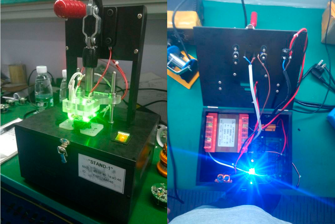
Calibration Stand
The use of the stand ensured high accuracy of power measurement, manufacturability and reliability of the product.
In the process of flashing the socket, a color palette was also laid down (the proportional ratio of red, blue and green colors). This color scale is used in the outlet by the LED rim to display the power consumed by the load connected to the device.
What is the result?
This was our first attempt to implement this functionality. Despite the fact that we went through a lot of options, there is also a positive side to this - by experience we decided on the microcircuit necessary for operation, having studied the pros and cons of all samples.
Our Wi-Fi outlet, having the ability to measure power, from an ordinary device capable of remotely controlling power supply, has become a smart device that greatly facilitates the user's life.
There is still a lot of work ahead, above we mentioned the whole Wi-Fi line, which is being developed right now. In addition to the outlet for purchase is already available, for example, the control module. Many other smart devices are preparing for the exit.
We will certainly tell about them in the following articles.
')
Source: https://habr.com/ru/post/344170/
All Articles