Arduino and segment LCD indicator
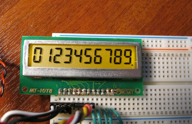
Arduino, as you know, has an excellent built-in library for displaying information on LCD indicators, which, however, only supports matrix sign-synthesizing indicators. It so happened that I had in my hands the usual segment indicator, the simplest 10-bit MT-10T8. The task was fully consistent with the ability of this indicator - to display the current temperature for a single device, which for simplicity we call a laboratory temperature meter. The device is controlled by the Arduino, specifically its kind of Seeduino Mega (analogue of the Arduino Mega). After a brief acquaintance with a rather concise datasheet on the MT-10T8, it was decided to spend a little time and make friends with this indicator Arduino.
The indicator uses a simple control protocol, the address and data are transmitted via a parallel 4-bit bus. The protocol does not represent any difficulties, the address of the symbol fits into 4 bits of the bus, data is transmitted by two tetrads of 4 bits (and that 8 bits per symbol). The only thing you should pay attention to and not confuse is the recommended timings of the indicator control signals. It is desirable that at least the CPU time is spent on accessing the indicator, but it is necessary to ensure stability, because, as practice has shown, the indicator very easily goes crazy.
The minimum delays of tens of nanoseconds required by the datasheet are not provided with Arduino, but after a brief search on the arduino website, there was an advice to use the “nop” assembler command for short delays
')
__asm__("nop\n\t");This design at 16 MHz crystal gives a delay of 62.5 ns. Datashit operates with minimum timings of 50, 100 and 200 nanoseconds, we will also have 62.5, 125 and 250 nanoseconds. It suits.

The indicator connection was made by improvised means, the resulting “Frankenstein” is shown in the photo. The control program uses the hardware function of the indicator to display the characters "in a row", i.e. if, after displaying a character at a specific address, call the next data transfer command without setting an address on the bus, the character will be displayed at the address following the current one.
Now you should probably answer the question - why? In fact, if a 10-bit matrix indicator costs 250 rubles, why use a minimalistic segment indicator, which is only 70 rubles. cheaper? Well, firstly, the ruble protects the penny, and secondly, to put it mildly, the LiquidCrystal library is not small in volume. And then minimalism taxis.
Actually the code, I think, it does not require special explanations. First, the functions themselves display information on the indicator:
// writeSymbol -
// address - (0..9)
// symbol -
// dot -
void writeSymbol(byte address, byte symbol, boolean dot)
{
//
//
digitalWrite(A0_PIN, LOW);
//
digitalWrite(DB0_PIN, bitRead(address,0));
digitalWrite(DB1_PIN, bitRead(address,1));
digitalWrite(DB2_PIN, bitRead(address,2));
digitalWrite(DB3_PIN, bitRead(address,3));
__asm__("nop\n\t"); //62.5ns
//
digitalWrite(WR1_PIN, HIGH);
__asm__("nop\n\t""nop\n\t"); //125.5ns
digitalWrite(WR1_PIN, LOW);
__asm__("nop\n\t"); //62.5ns
//
writeNextSymbol(symbol, dot);
}

// writeNextSymbol - ,
// symbol -
// dot -
void writeNextSymbol(byte symbol, boolean dot)
{
if (dot)
symbol+=16;
//
digitalWrite(DB0_PIN, bitRead(symbol,0));
digitalWrite(DB1_PIN, bitRead(symbol,1));
digitalWrite(DB2_PIN, bitRead(symbol,2));
digitalWrite(DB3_PIN, bitRead(symbol,3));
//
digitalWrite(A0_PIN, HIGH);
// WR
__asm__("nop\n\t""nop\n\t""nop\n\t""nop\n\t"); //250ns
//
digitalWrite(WR1_PIN, HIGH);
__asm__("nop\n\t""nop\n\t"); //125.5ns
digitalWrite(WR1_PIN, LOW);
//
//
digitalWrite(DB0_PIN, bitRead(symbol,4));
digitalWrite(DB1_PIN, bitRead(symbol,5));
digitalWrite(DB2_PIN, bitRead(symbol,6));
digitalWrite(DB3_PIN, bitRead(symbol,7));
// WR
__asm__("nop\n\t""nop\n\t""nop\n\t""nop\n\t"); //250ns
//
digitalWrite(WR1_PIN, HIGH);
__asm__("nop\n\t""nop\n\t"); //125.5ns
digitalWrite(WR1_PIN, LOW);
}

// clearAll -
void clearAll()
{
for (int i=0;i<10;i++)
{
writeSymbol(i, 0, false);
}
}

// unblockBus- /.
// ,
//
void unblockBus()
{
//
digitalWrite(A0_PIN, LOW);
// 0F -
digitalWrite(DB0_PIN, HIGH);
digitalWrite(DB1_PIN, HIGH);
digitalWrite(DB2_PIN, HIGH);
digitalWrite(DB3_PIN, HIGH);
__asm__("nop\n\t"); //62.5ns
//
digitalWrite(WR1_PIN, HIGH);
__asm__("nop\n\t""nop\n\t"); //125.5ns
digitalWrite(WR1_PIN, LOW);
__asm__("nop\n\t"); //62.5ns
// : DB0=1
digitalWrite(DB0_PIN, HIGH);
digitalWrite(DB1_PIN, LOW);
digitalWrite(DB2_PIN, LOW);
digitalWrite(DB3_PIN, LOW);
//
digitalWrite(A0_PIN, HIGH);
// WR
__asm__("nop\n\t""nop\n\t""nop\n\t""nop\n\t"); //250ns
//
digitalWrite(WR1_PIN, HIGH);
__asm__("nop\n\t""nop\n\t"); //125.5ns
digitalWrite(WR1_PIN, LOW);
}
And an example of combat use:
// , Arduino
const byte A0_PIN=10;
const byte WR1_PIN=8;
const byte WR2_PIN=9;
const byte DB0_PIN=2;
const byte DB1_PIN=3;
const byte DB2_PIN=4;
const byte DB3_PIN=5;

//
//
const byte SEG_A=8;
const byte SEG_B=32;
const byte SEG_C=64;
const byte SEG_D=4;
const byte SEG_E=2;
const byte SEG_F=128;
const byte SEG_G=1;
const byte SEG_H=16;

// " ".
const byte WHITESPACE = 0; //
//
const byte DIGIT_ZERO = SEG_A + SEG_B + SEG_C + SEG_D + SEG_E + SEG_F;
const byte DIGIT_ONE = SEG_B + SEG_C;
const byte DIGIT_TWO = SEG_A + SEG_B + SEG_G + SEG_E + SEG_D;
const byte DIGIT_THREE = SEG_A + SEG_B + SEG_G + SEG_C+ SEG_D;
const byte DIGIT_FOUR = SEG_F + SEG_G + SEG_B + SEG_C;
const byte DIGIT_FIVE = SEG_A + SEG_F + SEG_G + SEG_C + SEG_D;
const byte DIGIT_SIX = SEG_A + SEG_F + SEG_G + SEG_C + SEG_D + SEG_E;
const byte DIGIT_SEVEN = SEG_A + SEG_B + SEG_C;
const byte DIGIT_EIGHT = SEG_A + SEG_B + SEG_C + SEG_D + SEG_E + SEG_F + SEG_G;
const byte DIGIT_NINE = SEG_A + SEG_B + SEG_C + SEG_D + SEG_F + SEG_G;

// .
const byte SYMBOL_MINUS = SEG_G;
const byte SYMBOL_C = SEG_A + SEG_F + SEG_E + SEG_D;
const byte SYMBOL_DEGREE= SEG_A + SEG_B + SEG_G + SEG_F;
const byte SYMBOL_UPDASH = SEG_A;
const byte SYMBOL_LOWDASH = SEG_D;

void setup() {
// , -
pinMode(A0_PIN, OUTPUT);
pinMode(WR1_PIN, OUTPUT);
pinMode(WR2_PIN, OUTPUT);
pinMode(DB0_PIN, OUTPUT);
pinMode(DB1_PIN, OUTPUT);
pinMode(DB2_PIN, OUTPUT);
pinMode(DB3_PIN, OUTPUT);
unblockBus();
}

void loop() {
//
clearAll();
delay(1000);
//
writeSymbol(0, DIGIT_ZERO, false);
delay(100);
writeNextSymbol( DIGIT_ONE, false);
delay(100);
writeNextSymbol( DIGIT_TWO, false);
delay(100);
writeNextSymbol( DIGIT_THREE, false);
delay(100);
writeNextSymbol( DIGIT_FOUR, false);
delay(100);
writeNextSymbol( DIGIT_FIVE, false);
delay(100);
writeNextSymbol( DIGIT_SIX, false);
delay(100);
writeNextSymbol( DIGIT_SEVEN, false);
delay(100);
writeNextSymbol( DIGIT_EIGHT, false);
delay(100);
writeNextSymbol( DIGIT_NINE, true);
delay(500);
clearAll();
writeSymbol(0, SYMBOL_MINUS, false);
delay(100);
writeNextSymbol( SYMBOL_C, false);
delay(100);
writeNextSymbol( SYMBOL_DEGREE, false);
delay(100);
writeNextSymbol( SYMBOL_UPDASH, false);
delay(100);
writeNextSymbol( SYMBOL_LOWDASH, false);
delay(1000);
clearAll();
// 156.4
writeSymbol(3, SYMBOL_MINUS, false);
writeNextSymbol( DIGIT_ONE, false);
writeNextSymbol( DIGIT_FIVE, false);
writeNextSymbol( DIGIT_SIX, true);
writeNextSymbol( DIGIT_FOUR, false);
writeNextSymbol( SYMBOL_DEGREE, false);
writeNextSymbol( SYMBOL_C, false);
delay(1000);
clearAll();
//
for (int i=0;i<10;i++)
{
writeSymbol(i, SYMBOL_UPDASH, false);
if (i>0) writeSymbol(i-1, WHITESPACE, false);
delay(200);
}
for (int i=0;i<10;i++)
{
writeSymbol(9-i, SYMBOL_LOWDASH, false);
delay(200);
}
delay(1000);
}
Source: https://habr.com/ru/post/343694/
All Articles