“Like a ram on a new gate” or custom “pseudo-3D” objects in NanoCAD using the MultiCAD.NET API
In my opinion, one of the best ways to learn something is to share knowledge with other people.
This time I needed to understand how to create custom objects in NanoCAD using the MultiCAD.NET API. Nanosoft’s blog has an article from 2013 that explains the basic issues of creating custom primitives . But it would not be interesting to agree, just to reproduce this article, so we will add it a bit.
In our case, we will create a pseudo-three-dimensional door , which will also be able to open and close. And so that our little door is not lonely, we will create a girlfriend for her - the same wall.
')
Under the concept of “pseudo-3D” in this case, I mean that our objects will not have the properties of a rigid body model, that is, it will simply be a set of connected geometric primitives in a three-dimensional coordinate system. Maybe this is not quite the correct term, but so far I have not picked up anything better.
Unfortunately, with all the desire you cannot call me a programmer right now, so this article will be in the style of a beginner to beginners and surely all the code and the techniques you meet in it can be improved.
Anyway, if you are interested in: design, CAD, NanoCAD, development under .NET and in particular in C #, as well as sheep and Sesame Street , then perhaps this article is just for you.
Are you also interested in where the sheep and Sesame Street are? Then you are welcome under the cat.

I will not force a dramatic pause, the sheep are a kind of metaphor explaining the meaninglessness of what we are going to do today (picture a little later).
Well, Sesame Street, here is simply because I recently remembered about her and I was smashed by a terrible nostalgia for the Muppets, so that they will help us withstand the uniform style of the story.
Probably it was stupid to reveal all the intrigue so quickly? But I hope that you still continue to read the article.
Content:
Part I: With the new CAD! (Introduction).
Part II: We write code under NanoCAD 8.5
Part III: Trying to adapt the code for a free NanoCAD 5.1.
Part IV: The Multi-Kukish (Conclusion)

I would like to start with the fact that a stable version of the fresh NanoCAD 8.5 SDK has become available on the NanoCAD developer portal and this time we will be guided by it.
In my last article focused on NanoCAD 8.1, I shared my opinion on the platform, we discussed the process of preparing the project for the assembly and wrote a simple command, so if you missed it and are completely unfamiliar with NanoCAD and developed using the MultiCAD .NET API, you can start from the article "Scarless Face" or the first steps in Multicad.NET API 7 (for Nanocad 8.1)
This time I plan to do less “pour water” and pay more attention to the technical side.
The only thing before going on to develop our facilities is to say that before starting the preparation of this article, I essentially only used the free versions of NanoCAD (NC 5.1), which was released in 2013 already.
There were two reasons for this: it is completely free for any purpose, and the second reason is that I have a very weak computer, so AutoCAD slows down on it and loads a hell of a lot.
But since before writing this article, I had to practice “pens” to draw the object, and also to understand how the three-dimensional viewing of the object works, well, and most importantly, restart the CAD 10,000 times during the debugging process, I had a little time to look at NanoCAD 8.5 .
So at first glance I can say the following, it is more pleasant to draw than in the old free version, and it loads as fast as the old NanoCAD 5.1, that is, NC 8.5 starts several times faster than its peer - AutoCAD 2017 (if anyone is curious, write in the comments, I will stopped with a stopwatch). It only remains to hope that one day the company will update the free version, transferring to it new APIs and new features in terms of the functions of the “electronic panel machine”.
And finally, as I understand in the versions of NanoCAD available for developers, the module of three-dimensional solid modeling is turned on, but I could not understand the API to it, especially for objects created by the user. Maybe another time we will study it. For now we will be content with "pseudo-3D" objects.
This even has its advantage, our library after a small adaptation will be launched in the free NanoCAD 5.1, where there is no solid modeling at all. But more on that later.

Yes, yes, Count von Znach counted everything correctly! Looking ahead to exactly so many sheep, walls and doors we get at the end. Now Count Znak will have a new assignment - count views and votes for the article. I can already hear it straight: “one, one view, two or two views, three ...”
As usual, the full code of the classes and an example of dwg files can be found on GitHub .
And now we will begin to disassemble it in parts. I did not begin to make ready-made assemblies, I think you will be able to build the project yourself, in the last article , I described in detail how to create and configure the project for MS Visual Studio 2015, for NanoCAD 8.1, and so nothing has changed since that moment.
Therefore, this time I will only briefly mention the procedure for assembling under Nanocad 8.5:
You naturally have the name of the project and the path to it may differ.
Well, that’s all, we’re ready for development, now, by pressing F5, NC 8.5 starts automatically and our assembly is loaded right away, all that remains is to enter the commands that we have developed.
Once again, I’m not a programmer, so most likely there will be a lot of flaws in the code: failures when saving, moving or copying objects, and simply non-optimal solutions. If someone, without greatly complicating the code, will be able to bring the ego to mind - “earthly bow”.
But anyway, on the basis of this code, we will be able to sort out a little how to create our objects, which means that it performs its main goal.
Well, of course, I must say a big thank you to Alexander Polkhovsky from the NanoCAD developers forum, he helped me a lot with redefining the functionality related to moving and rotating an object (useful for opening / closing the door). Yes, and to all the other forum participants, too, thank you, I will remind that at the moment one of the most accessible sources of information on the MultiCAD.NET API.
We start with the wall, because it is simpler in execution.
First, let's add namespaces.
Then create a custom object class.
Take the class name you want (you can leave mine as well), the main thing is that it inherit from McCustomBase.
All class attributes are required, I honestly do not fully understand the parameters of the CustomEntity attribute, so I stupidly remade it by analogy.
“8b0986c0-4163-42a4-b005-187111b499d7” - in my example, this is a GUID, I apparently “clicked” the moment where the .NET documentation explained how to work with it. I can only say one thing. For simplicity, I took it from the assembly settings file, replacing the last digit to ensure uniqueness. If the GUID of the door and wall classes is completely the same, miracles will begin: when copying, the doors will turn into doors and the doors will lose their functionality after saving the file, I’ve fixed it, I hope, and you will have no problems.
Define the class fields.
The fields _pnt1 and _pnt12 are the base points on which the geometry of our wall will be built (the length of the wall is in fact), _h is the wall height by default (after creating an object you can correct it).
Next, create a team on call, which will outline our door.
DrawWall in the CommandMethod attribute is the name of the command that you will enter on the command line to call an object, you can shorten it, for example, with a DWall, without losing functionality.
We in the class implementing our team create a new instance of the wall class (if this is not done, then all the walls in my office will begin to be perceived as one “uber” wall). And we will define the PlaceObject method a bit later.
We define the procedure for drawing the object.
I do not fully understand this piece, but somehow the API has a GeometryBuilder class, on the basis of which we will continue to sculpt our wall.
Dc.Clear, apparently clears every time all the geometry previously built for an instance of a class.
Further easier.
We define four base points on the basis of which the base and top of the wall will be built, with the first and second points being linked to the class fields, which means we will be manipulating them later. Our wall in length will be built according to the distance between the _pnt1 and pnt2 points, but the wall width is set rigidly and cannot be corrected (this is done for simplicity), but you can easily redefine the logic of work by analogy.
dc.Color - seems to set the "color by block" property for an object.
The vector hvec is the height of our wall, which we will add to the base to build the top.
Next we draw the lower and upper sides of the wall.
We connect bottom and top with ribs.
Create a contour from pollinium for hatching and then fill it with brick hatching (you can see the names of the hatchings in the program itself). And I did not manage to shade through the list of polylines I had to repeat the procedure twice. I think I did not take into account something.
We only shade 2 wall surfaces - the longest, if you want you can shade the rest yourself.
Define a custom property for an object, since in my opinion it is more convenient to draw in a two-dimensional form, it is not convenient to set the wall height at the moment of drawing, it was possible to make the installation of the wall height as part of its drawing procedure, but we will go more simply by adding a property the help of which we will change the height after it is drawn.
According to the attributes [DisplayName ("Height")] - the name that will be in the properties window, [Description ("Height of wall")], is a description, but I did not understand where it is displayed, [Category ("Wall options")] - category of fields, as you will see later on the example of the doors, it is fashionable to group our fields for convenience.
Well, then the property usually goes on, if you ever made public properties in Unity 3D, then the mechanism is similar, we can have access to the class fields directly from the editor (in our case from CAD).
TryModify () is a required method, it must be called before each change in the properties of an object, as I understood. We will meet with him a couple of times.
Next, we redefine the method responsible for placing the object in the drawing (remember, we used to call it before).
This code is almost entirely borrowed from the example from Nanosoft I mentioned in the first chapter, I do not understand it 100%, but if in short we call the command to enter the first point of the wall (jig.GetPoint), then put it into the drawing (DbEntity. AddToCurrentDocument ()), after which we exclude the object from the bindings so that it does not prevent us from entering the second point (_pnt2).
If everything is normal, then the object is placed in the drawing, if not (for example, input is not completed), then the object is deleted.
And the last do the handles to change the size of the wall.
As I understand it, the code from the example I mentioned above is obsolete in terms of pens (for NC 8.X) and it is better to focus on the code from this example .
Well, of course, I’m warning you that my code is far from ideal, so I’ll be happy with adequate, imputed edits.
Now consider the door. The beginning is the same.
Unless a field was added that will be responsible for whether our door is open or closed, and two vectors will appear _vecStraightDirection - responsible for the current door turn, _vecDirectionClosed - stores data on the door turn in the closed state. This will all come in handy later.
But directly in the geometry of the door, as you would expect there are small changes.
First, note that we build the door one point at a time, that is, the size of the door is rigidly fixed in width and height (well, so that it differs from the wall). Also, the section “// Drawing a Door Handle” was added, there are 2 lines that indicate a conventional handle, and we also replaced the type of hatching with JIS_WOOD
But the PlaceObject method is simpler here, due to the fact that the second handle is not needed.
Next comes the complete novelty with respect to the wall class. For which I thanked Alexander at the beginning of the article.
Below, we will redefine the method that is in some mysterious way responsible for creating the transformation matrix (displacement and rotation) of our door.
I do not fully understand the work of this method, but it seems that with each movement it transforms our door depending on the base point and the rotation vector, this ultimately allows us to open or close the door in the drawing.
Next, we redefine the event that seems to occur when the object is transformed.
To begin with, I will say that in order not to get stuck with the development, I simplified some points, especially those solutions that were given to me with difficulty. One of these simplifications is the restriction on door manipulation.
You can only move, rotate, copy and somehow change the door in the closed state (it is installed by default).
In order for it to work this way, we create an undo object and mark the starting point for committing changes.
After that, if everything is normal, we transfer the state _pnt1 and the vector ._vecStraightDirection to their state after transformation.
Then the condition is checked, if the door was closed, the changes are applied and additionally entered into a vector that stores the position of the closed door.
If the door was open (or ajar), we give an error message and discard all changes.
The door height field is similar to a wall.
But the next field - new
It is here that we are responsible for the state of the door, a drop-down list appears in the properties window with the values: closed, middle, open (one to one, as the definition of the first class enumeration).
When choosing each of the values, the vector responsible for turning the door eventually changes.
When closed, it is set to the previously saved state of _vecDirectionClosed;
In the half-open state, the resulting vector is obtained, which rotates our door at an angle of about 30 degrees, so that it is similar to the designation according to GOST.
When open, we just take a perpendicular to our closed state vector with a negative value (so that the door opens down by default).
I think the default case is not needed at all, but I left it.
Well, the last is a handle for manipulation.
For it you can drag and all. From time to time, I have pens on both objects, wherever I go, but I don’t have the strength to debug it (I thought I would finish the article faster, and I had already killed three full days).
So, press F5 and use the DRAWWALL and DRAWDOOR commands to insert our doors and walls.
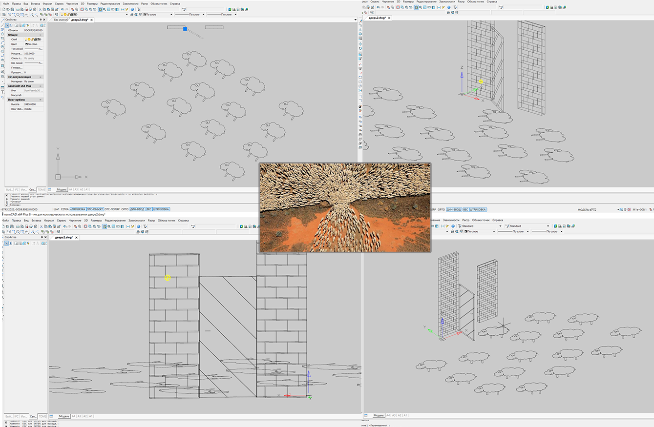
As a result, we get what's in the picture. On it I show you the work of the library from 4 different angles. Sheep unfortunately flat, and I drew them by hand. Well, the doors with walls slightly differ from those in the latest version of the .dwg file on GitHub, just made a couple of edits, and it was too lazy to retake screenshots.
If you will be loading your library manually with the NETLOAD command, remember that it must be loaded before opening the file with our objects, or they are recognized as proxy objects.
For those who are new to working with Nanocad, I remind you that getting a three-dimensional view of your objects is conveniently done like this: view-> orbit-> dependent orbit, and you can return the two-dimensional view back like this: view-> views and projections-> view in plan-> current UCS.

In the last article, for some reason, the face painting team did not work for me, but this time we managed to adapt the code and our object is launched with some limitations in the free version of NanoCAD 5.1.
To begin, briefly tell you how to set up the environment, almost no difference.
Therefore, I again only briefly mention the procedure for assembling under Nanocad 5.1:
Your file paths will be yours.
The code will not drastically differ, so I will hide both classes under the spoiler and explain only the differences.
So, the wall:
What is the difference, firstly, when I tried to insert objects into an empty drawing, then Nanocad scaled it to me so that neither the wall nor the door could be seen, and I added a field with a scale.
For a wall, it changes the thickness of the wall, and for a door, it changes its thickness and length.
Accordingly, the necessary coordinates are now multiplied by the scale for which there is an open property.
And the second difference in the old version of the MultiCAD.NET API is that there is no class for working with hatching, I can assume that it can be implemented through the API for regular .NET, but I did not.
Now the door:
Again, almost everything is the same, the only thing is that in version 5.1 it looks like the field processes enumerations differently and in the object properties window instead of closed / open, we will see enumeration values: 0, 1, 2 this is not very obvious, so we slightly changed the warning about by mistake. Also, the door has no hatching and there is an extra property for scale (by the way, if you wish, you can also implement it in classes for NC 8.5).
It turns out like this:

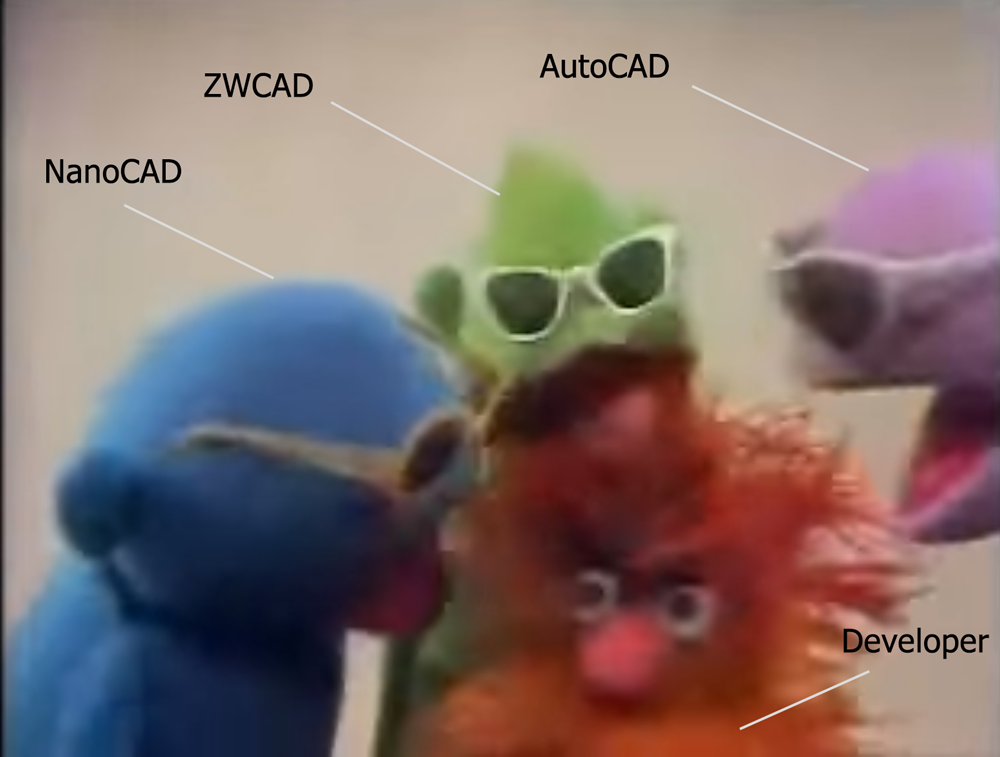
As you remember from the last article, Nanosoft and I are in no way connected, which means I can afford a small element of criticism. The developers declare support for the MultiCAD.NET API in AutoCAD and ZWCAD through a certain layer, there is even an article about it .
But it seems that this is a non-priority direction of development. In the last article, I wrote that I could not test this function because I have AutoCAD 2017 installed on my computer, and the last layer posted on the developers' website - “MultiCAD_AC_ZC_Enabler_2209_RU.zip” (which is already 1.5 years old) does not support anything older than AutoCAD 2016. For the sake of such pleasure, I did not want another version of AutoCAD.
This time I decided to try another option, downloaded the trial version of ZWCAD + 2015, again the latest version that this layer supports. I don’t know, maybe I’ve got a “handle”, but neither this library nor the library from the previous article ever “flew up” in ZWCAD. Therefore, if someone succeeds in running it, and he will share a screenshot, I will be grateful.
But as for the rest, I must say that the more you fiddle with this API, the more you pull in and even start to enjoy a little, it is noticeable that the API is improving, some members of the API classes already have a valid description in Russian, and the API itself becomes more self-sufficient.
I think that when NanoCAD 9 comes out (or whatever they call it) with support for DWG 2018, it will be even better (especially if the developers promised at the forum, it will be followed by a new free NanoCad ).
So I want to say to all participants of the Nanocad Developer Forum - thanks for the help, developers - thanks for posting NC 8.5, and for all readers - thanks for mastering the article to the end.
PS , , « » ( , ). …
This time I needed to understand how to create custom objects in NanoCAD using the MultiCAD.NET API. Nanosoft’s blog has an article from 2013 that explains the basic issues of creating custom primitives . But it would not be interesting to agree, just to reproduce this article, so we will add it a bit.
In our case, we will create a pseudo-three-dimensional door , which will also be able to open and close. And so that our little door is not lonely, we will create a girlfriend for her - the same wall.
')
Under the concept of “pseudo-3D” in this case, I mean that our objects will not have the properties of a rigid body model, that is, it will simply be a set of connected geometric primitives in a three-dimensional coordinate system. Maybe this is not quite the correct term, but so far I have not picked up anything better.
Unfortunately, with all the desire you cannot call me a programmer right now, so this article will be in the style of a beginner to beginners and surely all the code and the techniques you meet in it can be improved.
Anyway, if you are interested in: design, CAD, NanoCAD, development under .NET and in particular in C #, as well as sheep and Sesame Street , then perhaps this article is just for you.
Are you also interested in where the sheep and Sesame Street are? Then you are welcome under the cat.
I will not force a dramatic pause, the sheep are a kind of metaphor explaining the meaninglessness of what we are going to do today (picture a little later).
Well, Sesame Street, here is simply because I recently remembered about her and I was smashed by a terrible nostalgia for the Muppets, so that they will help us withstand the uniform style of the story.
Probably it was stupid to reveal all the intrigue so quickly? But I hope that you still continue to read the article.
Content:
Part I: With the new CAD! (Introduction).
Part II: We write code under NanoCAD 8.5
Part III: Trying to adapt the code for a free NanoCAD 5.1.
Part IV: The Multi-Kukish (Conclusion)
1. With the new CAD! (Introduction).
I would like to start with the fact that a stable version of the fresh NanoCAD 8.5 SDK has become available on the NanoCAD developer portal and this time we will be guided by it.
In my last article focused on NanoCAD 8.1, I shared my opinion on the platform, we discussed the process of preparing the project for the assembly and wrote a simple command, so if you missed it and are completely unfamiliar with NanoCAD and developed using the MultiCAD .NET API, you can start from the article "Scarless Face" or the first steps in Multicad.NET API 7 (for Nanocad 8.1)
This time I plan to do less “pour water” and pay more attention to the technical side.
The only thing before going on to develop our facilities is to say that before starting the preparation of this article, I essentially only used the free versions of NanoCAD (NC 5.1), which was released in 2013 already.
There were two reasons for this: it is completely free for any purpose, and the second reason is that I have a very weak computer, so AutoCAD slows down on it and loads a hell of a lot.
But since before writing this article, I had to practice “pens” to draw the object, and also to understand how the three-dimensional viewing of the object works, well, and most importantly, restart the CAD 10,000 times during the debugging process, I had a little time to look at NanoCAD 8.5 .
So at first glance I can say the following, it is more pleasant to draw than in the old free version, and it loads as fast as the old NanoCAD 5.1, that is, NC 8.5 starts several times faster than its peer - AutoCAD 2017 (if anyone is curious, write in the comments, I will stopped with a stopwatch). It only remains to hope that one day the company will update the free version, transferring to it new APIs and new features in terms of the functions of the “electronic panel machine”.
And finally, as I understand in the versions of NanoCAD available for developers, the module of three-dimensional solid modeling is turned on, but I could not understand the API to it, especially for objects created by the user. Maybe another time we will study it. For now we will be content with "pseudo-3D" objects.
This even has its advantage, our library after a small adaptation will be launched in the free NanoCAD 5.1, where there is no solid modeling at all. But more on that later.
2. We write code under NanoCAD 8.5
Yes, yes, Count von Znach counted everything correctly! Looking ahead to exactly so many sheep, walls and doors we get at the end. Now Count Znak will have a new assignment - count views and votes for the article. I can already hear it straight: “one, one view, two or two views, three ...”
As usual, the full code of the classes and an example of dwg files can be found on GitHub .
And now we will begin to disassemble it in parts. I did not begin to make ready-made assemblies, I think you will be able to build the project yourself, in the last article , I described in detail how to create and configure the project for MS Visual Studio 2015, for NanoCAD 8.1, and so nothing has changed since that moment.
Therefore, this time I will only briefly mention the procedure for assembling under Nanocad 8.5:
- Create a new project. Select the platform. NET Framework 4, as a template, select the class library C #.
- For the Nanocad version of x64 (and I have this) from the SDK \ include-x64 \ folder, add links to the project to: mapibasetypes.dll, mapimgd.dll, imapimgd.dll. Do not forget for all three libraries to copy the property locally to False.
- Also add links to the assembly from Microsoft: System.Windows.Forms.dll, System.Drawing.dll.
- In the project properties, on the “Debug” tab, as an action at startup, select “open in external program” and specify the path to the NC 8.5 executable file (I have C: \ Program Files \ Nanosoft \ nanoCAD x64 Plus 8.5 \ nCad.exe )
- Create two classes DoorPseudo3D.cs and WalllPseudo3D.cs for the door and the wall respectively.
- Let's go to the address C: \ ProgramData \ Nanosoft \ nanoCAD x64 Plus 8.5 \ DataRW (you may differ) and find or create the file load.config with the following content
<root> <list> <module path="C:\Users\...\bin\Debug\nanodoor2.dll"/> </list> </root> You naturally have the name of the project and the path to it may differ.
Well, that’s all, we’re ready for development, now, by pressing F5, NC 8.5 starts automatically and our assembly is loaded right away, all that remains is to enter the commands that we have developed.
Once again, I’m not a programmer, so most likely there will be a lot of flaws in the code: failures when saving, moving or copying objects, and simply non-optimal solutions. If someone, without greatly complicating the code, will be able to bring the ego to mind - “earthly bow”.
But anyway, on the basis of this code, we will be able to sort out a little how to create our objects, which means that it performs its main goal.
Well, of course, I must say a big thank you to Alexander Polkhovsky from the NanoCAD developers forum, he helped me a lot with redefining the functionality related to moving and rotating an object (useful for opening / closing the door). Yes, and to all the other forum participants, too, thank you, I will remind that at the moment one of the most accessible sources of information on the MultiCAD.NET API.
We start with the wall, because it is simpler in execution.
First, let's add namespaces.
using System; using System.Collections.Generic; using System.ComponentModel; using Multicad.Runtime; using Multicad.DatabaseServices; using Multicad.Geometry; using Multicad.CustomObjectBase; using Multicad; Then create a custom object class.
namespace nanowall2 { //change "8b0986c0-4163-42a4-b005-187111b499d7" for your Guid from Assembly. // Be careful GUID for door and wall classes must be different! // Otherwise there will be problems with saving and moving [CustomEntity(typeof(WalllPseudo3D), "8b0986c0-4163-42a4-b005-187111b499d7", "WalllPseudo3D", "WalllPseudo3D Sample Entity")] [Serializable] public class WalllPseudo3D : McCustomBase { Take the class name you want (you can leave mine as well), the main thing is that it inherit from McCustomBase.
All class attributes are required, I honestly do not fully understand the parameters of the CustomEntity attribute, so I stupidly remade it by analogy.
“8b0986c0-4163-42a4-b005-187111b499d7” - in my example, this is a GUID, I apparently “clicked” the moment where the .NET documentation explained how to work with it. I can only say one thing. For simplicity, I took it from the assembly settings file, replacing the last digit to ensure uniqueness. If the GUID of the door and wall classes is completely the same, miracles will begin: when copying, the doors will turn into doors and the doors will lose their functionality after saving the file, I’ve fixed it, I hope, and you will have no problems.
Define the class fields.
private Point3d _pnt1 = new Point3d(100, 100, 0); private Point3d _pnt2 = new Point3d(500, 100, 0); private double _h = 2085; The fields _pnt1 and _pnt12 are the base points on which the geometry of our wall will be built (the length of the wall is in fact), _h is the wall height by default (after creating an object you can correct it).
Next, create a team on call, which will outline our door.
DrawWall in the CommandMethod attribute is the name of the command that you will enter on the command line to call an object, you can shorten it, for example, with a DWall, without losing functionality.
[CommandMethod("DrawWall", CommandFlags.NoCheck | CommandFlags.NoPrefix)] public void DrawWall() { WalllPseudo3D wall = new WalllPseudo3D(); wall.PlaceObject(); } We in the class implementing our team create a new instance of the wall class (if this is not done, then all the walls in my office will begin to be perceived as one “uber” wall). And we will define the PlaceObject method a bit later.
We define the procedure for drawing the object.
public override void OnDraw(GeometryBuilder dc) { dc.Clear(); I do not fully understand this piece, but somehow the API has a GeometryBuilder class, on the basis of which we will continue to sculpt our wall.
Dc.Clear, apparently clears every time all the geometry previously built for an instance of a class.
Further easier.
Point3d pnt1 = _pnt1; Point3d pnt2 = new Point3d(_pnt2.X, pnt1.Y, 0); Point3d pnt3 = new Point3d(pnt2.X, pnt1.Y+150, 0); Point3d pnt4 = new Point3d(pnt1.X , pnt3.Y, 0); // Set the color to ByObject value dc.Color = McDbEntity.ByObject; Vector3d hvec = new Vector3d(0, 0, _h); We define four base points on the basis of which the base and top of the wall will be built, with the first and second points being linked to the class fields, which means we will be manipulating them later. Our wall in length will be built according to the distance between the _pnt1 and pnt2 points, but the wall width is set rigidly and cannot be corrected (this is done for simplicity), but you can easily redefine the logic of work by analogy.
dc.Color - seems to set the "color by block" property for an object.
The vector hvec is the height of our wall, which we will add to the base to build the top.
Next we draw the lower and upper sides of the wall.
dc.DrawPolyline(new Point3d[] { pnt1, pnt2, pnt3, pnt4, _pnt1 }); dc.DrawPolyline(new Point3d[] { _pnt1.Add(hvec), pnt2.Add(hvec), pnt3.Add(hvec), pnt4.Add(hvec), pnt1.Add(hvec)}); We connect bottom and top with ribs.
dc.DrawLine(pnt1, pnt1.Add(hvec)); dc.DrawLine(pnt2, pnt2.Add(hvec)); dc.DrawLine(pnt3, pnt3.Add(hvec)); dc.DrawLine(pnt4, pnt4.Add(hvec)); Create a contour from pollinium for hatching and then fill it with brick hatching (you can see the names of the hatchings in the program itself). And I did not manage to shade through the list of polylines I had to repeat the procedure twice. I think I did not take into account something.
We only shade 2 wall surfaces - the longest, if you want you can shade the rest yourself.
// Create contours for the front and rear sides and hatch them // In this demo, we hatch only two sides, you can tailor the others yourself List<Polyline3d> c1 = new List<Polyline3d>(); c1.Add(new Polyline3d( new List<Point3d>() { pnt1, pnt1.Add(hvec), pnt2.Add(hvec), pnt2, pnt1, })); dc.DrawGeometry(new Hatch(c1, "BRICK", 0, 20, false, HatchStyle.Normal, PatternType.PreDefined, 30), 1); List<Polyline3d> c2 = new List<Polyline3d>(); c2.Add(new Polyline3d( new List<Point3d>() { pnt4, pnt4.Add(hvec), pnt3.Add(hvec), pnt3, pnt4, })); dc.DrawGeometry(new Hatch(c2, "BRICK", 0, 20, false, HatchStyle.Normal, PatternType.PreDefined, 30), 1); } Define a custom property for an object, since in my opinion it is more convenient to draw in a two-dimensional form, it is not convenient to set the wall height at the moment of drawing, it was possible to make the installation of the wall height as part of its drawing procedure, but we will go more simply by adding a property the help of which we will change the height after it is drawn.
//Define the custom properties of the object [DisplayName("Height")] [Description("Height of wall")] [Category("Wall options")] public double HWall { get { return _h; } set { //Save Undo state and set the object status to "Changed" if (!TryModify()) return; _h = value; } } According to the attributes [DisplayName ("Height")] - the name that will be in the properties window, [Description ("Height of wall")], is a description, but I did not understand where it is displayed, [Category ("Wall options")] - category of fields, as you will see later on the example of the doors, it is fashionable to group our fields for convenience.
Well, then the property usually goes on, if you ever made public properties in Unity 3D, then the mechanism is similar, we can have access to the class fields directly from the editor (in our case from CAD).
TryModify () is a required method, it must be called before each change in the properties of an object, as I understood. We will meet with him a couple of times.
Next, we redefine the method responsible for placing the object in the drawing (remember, we used to call it before).
public override hresult PlaceObject(PlaceFlags lInsertType) { InputJig jig = new InputJig(); // Get the first box point from the jig InputResult res = jig.GetPoint("Select first point:"); if (res.Result != InputResult.ResultCode.Normal) return hresult.e_Fail; _pnt1 = res.Point; // Add the object to the database this.DbEntity.AddToCurrentDocument(); //Exclude the object from snap points jig.ExcludeObject(ID); // Monitoring mouse moving and interactive entity redrawing jig.MouseMove = (s, a) => { TryModify(); _pnt2 = a.Point; this.DbEntity.Update(); }; // Get the second box point from the jig res = jig.GetPoint("Select second point:"); if (res.Result != InputResult.ResultCode.Normal) { this.DbEntity.Erase(); return hresult.e_Fail; } _pnt2 = res.Point; return hresult.s_Ok; } This code is almost entirely borrowed from the example from Nanosoft I mentioned in the first chapter, I do not understand it 100%, but if in short we call the command to enter the first point of the wall (jig.GetPoint), then put it into the drawing (DbEntity. AddToCurrentDocument ()), after which we exclude the object from the bindings so that it does not prevent us from entering the second point (_pnt2).
If everything is normal, then the object is placed in the drawing, if not (for example, input is not completed), then the object is deleted.
And the last do the handles to change the size of the wall.
// Create a grip for the base point of the object public override bool GetGripPoints(GripPointsInfo info) { info.AppendGrip(new McSmartGrip<WalllPseudo3D>(_pnt1, (obj, g, offset) => { obj.TryModify(); obj._pnt1 += offset; })); info.AppendGrip(new McSmartGrip<WalllPseudo3D>(_pnt2, (obj, g, offset) => { obj.TryModify(); obj._pnt2 += offset; })); return true; } } // TODO: There are many shortcomings in this code. // Including failures when working with copying, moving objects and saving files, you can improve it if you want. } As I understand it, the code from the example I mentioned above is obsolete in terms of pens (for NC 8.X) and it is better to focus on the code from this example .
Well, of course, I’m warning you that my code is far from ideal, so I’ll be happy with adequate, imputed edits.
Now consider the door. The beginning is the same.
using System; using System.Collections.Generic; using System.ComponentModel; using System.Windows.Forms; using Multicad.Runtime; using Multicad.DatabaseServices; using Multicad.Geometry; using Multicad.CustomObjectBase; using Multicad; namespace nanodoor2 { //change "8b0986c0-4163-42a4-b005-187111b499d7" for your Guid from Assembly. // Be careful GUID for door and wall classes must be different! // Otherwise there will be problems with saving and moving [CustomEntity(typeof(DoorPseudo3D), "8b0986c0-4163-42a4-b005-187111b499d9", "DoorPseudo3D", "DoorPseudo3D Sample Entity")] [Serializable] public class DoorPseudo3D : McCustomBase { // First and second vertices of the box private Point3d _pnt1 = new Point3d(0, 0, 0); private double _h = 2085; private Vector3d _vecStraightDirection = new Vector3d(1, 0, 0); private Vector3d _vecDirectionClosed = new Vector3d(1, 0, 0); public enum status { closed , middle, open }; private status _dStatus = status.closed; [CommandMethod("DrawDoor", CommandFlags.NoCheck | CommandFlags.NoPrefix)] public void DrawDoor() { DoorPseudo3D door = new DoorPseudo3D(); door.PlaceObject(); } Unless a field was added that will be responsible for whether our door is open or closed, and two vectors will appear _vecStraightDirection - responsible for the current door turn, _vecDirectionClosed - stores data on the door turn in the closed state. This will all come in handy later.
But directly in the geometry of the door, as you would expect there are small changes.
public override void OnDraw(GeometryBuilder dc) { dc.Clear(); // Define the basic points for drawing Point3d pnt1 = new Point3d(0, 0, 0); Point3d pnt2 = new Point3d(pnt1.X + 984, pnt1.Y, 0); Point3d pnt3 = new Point3d(pnt2.X + 0, pnt1.Y+50, 0); Point3d pnt4 = new Point3d(pnt1.X , pnt3.Y, 0); // Set the color to ByObject value dc.Color = McDbEntity.ByObject; Vector3d hvec = new Vector3d(0, 0, _h); // Draw the upper and lower sides dc.DrawPolyline(new Point3d[] { pnt1, pnt2, pnt3, pnt4, pnt1 }); dc.DrawPolyline(new Point3d[] { pnt1.Add(hvec), pnt2.Add(hvec), pnt3.Add(hvec), pnt4.Add(hvec), pnt1.Add(hvec)}); // Draw the edges dc.DrawLine(pnt1, pnt1.Add(hvec)); dc.DrawLine(pnt2, pnt2.Add(hvec)); dc.DrawLine(pnt3, pnt3.Add(hvec)); dc.DrawLine(pnt4, pnt4.Add(hvec)); // Drawing a Door Handle dc.DrawLine(pnt2.Add(new Vector3d( - 190, -0, _h*0.45)), pnt2.Add(new Vector3d(-100, 0, _h * 0.45))); dc.DrawLine(pnt3.Add(new Vector3d(-190, 0, _h * 0.45)), pnt3.Add(new Vector3d(-100, 0, _h * 0.45))); // Create contours for the front and rear sides and hatch them // In this demo, we hatch only two sides, you can tailor the others yourself List<Polyline3d> c1 = new List<Polyline3d>(); c1.Add(new Polyline3d( new List<Point3d>() { pnt1, pnt1.Add(hvec), pnt2.Add(hvec), pnt2, pnt1, })); List<Polyline3d> c2 = new List<Polyline3d>(); c2.Add(new Polyline3d( new List<Point3d>() { pnt4, pnt4.Add(hvec), pnt3.Add(hvec), pnt3, pnt4, })); dc.DrawGeometry(new Hatch(c1, "JIS_WOOD", 0, 170, false, HatchStyle.Normal, PatternType.PreDefined, 500), 1); dc.DrawGeometry(new Hatch(c2, "JIS_WOOD", 0, 170, false, HatchStyle.Normal, PatternType.PreDefined, 500), 1); } First, note that we build the door one point at a time, that is, the size of the door is rigidly fixed in width and height (well, so that it differs from the wall). Also, the section “// Drawing a Door Handle” was added, there are 2 lines that indicate a conventional handle, and we also replaced the type of hatching with JIS_WOOD
But the PlaceObject method is simpler here, due to the fact that the second handle is not needed.
public override hresult PlaceObject(PlaceFlags lInsertType) { InputJig jig = new InputJig(); // Get the first box point from the jig InputResult res = jig.GetPoint("Select first point:"); if (res.Result != InputResult.ResultCode.Normal) return hresult.e_Fail; _pnt1 = res.Point; // Add the object to the database DbEntity.AddToCurrentDocument(); return hresult.s_Ok; } Next comes the complete novelty with respect to the wall class. For which I thanked Alexander at the beginning of the article.
Below, we will redefine the method that is in some mysterious way responsible for creating the transformation matrix (displacement and rotation) of our door.
/// <summary> /// Method for changing the object's SC (the graph is built at the origin of coordinates). /// </ summary> /// <param name = "tfm"> The matrix for changing the position of the object. </ param> /// <returns> True - if the matrix is passed, False - if not. </ returns> public override bool GetECS(out Matrix3d tfm) { // Create a matrix that transforms the object. // The object is drawn in coordinates(0.0), then it is transformed with the help of this matrix. tfm = Matrix3d.Displacement(this._pnt1.GetAsVector()) * Matrix3d.Rotation (-this._vecStraightDirection.GetAngleTo(Vector3d.XAxis, Vector3d.ZAxis), Vector3d.ZAxis, Point3d.Origin); return true; } I do not fully understand the work of this method, but it seems that with each movement it transforms our door depending on the base point and the rotation vector, this ultimately allows us to open or close the door in the drawing.
Next, we redefine the event that seems to occur when the object is transformed.
public override void OnTransform(Matrix3d tfm) { // To be able to cancel(Undo) McUndoPoint undo = new McUndoPoint(); undo.Start(); // Get the coordinates of the base point and the rotation vector this.TryModify(); this._pnt1 = this._pnt1.TransformBy(tfm); this.TryModify(); this._vecStraightDirection = this._vecStraightDirection.TransformBy(tfm); // We move the door only when it is closed if not - undo if (_dStatus == status.closed) _vecDirectionClosed = _vecStraightDirection; else { MessageBox.Show("Please transform only closed door"); undo.Undo(); } undo.Stop(); } To begin with, I will say that in order not to get stuck with the development, I simplified some points, especially those solutions that were given to me with difficulty. One of these simplifications is the restriction on door manipulation.
You can only move, rotate, copy and somehow change the door in the closed state (it is installed by default).
In order for it to work this way, we create an undo object and mark the starting point for committing changes.
After that, if everything is normal, we transfer the state _pnt1 and the vector ._vecStraightDirection to their state after transformation.
Then the condition is checked, if the door was closed, the changes are applied and additionally entered into a vector that stores the position of the closed door.
If the door was open (or ajar), we give an error message and discard all changes.
The door height field is similar to a wall.
//Define the custom properties of the object [DisplayName("Height")] [Description("Height of door")] [Category("Door options")] public double HDoor { get { return _h; } set { //Save Undo state and set the object status to "Changed" if (!TryModify()) return; _h = value; } } But the next field - new
[DisplayName("Door status")] [Description("Door may be: closed, middle, open")] [Category("Door options")] public status Stat { get { return _dStatus; } set { //Save Undo state and set the object status to "Changed" if (!TryModify()) return; // Change the rotation vector for each of the door states switch (value) { case status.closed: _vecStraightDirection = _vecDirectionClosed; break; case status.middle: _vecStraightDirection = _vecDirectionClosed.Add(_vecDirectionClosed.GetPerpendicularVector().Negate() * 0.575) ; break; case status.open: _vecStraightDirection = _vecDirectionClosed.GetPerpendicularVector()*-1; break; default: _vecStraightDirection = _vecDirectionClosed; break; } _dStatus = value; } } It is here that we are responsible for the state of the door, a drop-down list appears in the properties window with the values: closed, middle, open (one to one, as the definition of the first class enumeration).
When choosing each of the values, the vector responsible for turning the door eventually changes.
When closed, it is set to the previously saved state of _vecDirectionClosed;
In the half-open state, the resulting vector is obtained, which rotates our door at an angle of about 30 degrees, so that it is similar to the designation according to GOST.
When open, we just take a perpendicular to our closed state vector with a negative value (so that the door opens down by default).
I think the default case is not needed at all, but I left it.
Well, the last is a handle for manipulation.
// Create a grip for the base point of the object public override bool GetGripPoints(GripPointsInfo info) { info.AppendGrip(new McSmartGrip<DoorPseudo3D>(_pnt1, (obj, g, offset) => { obj.TryModify(); obj._pnt1 += offset; })); return true; } // TODO: There are many shortcomings in this code. // Including failures when working with copying, moving objects and saving files, you can improve it if you want. } For it you can drag and all. From time to time, I have pens on both objects, wherever I go, but I don’t have the strength to debug it (I thought I would finish the article faster, and I had already killed three full days).
So, press F5 and use the DRAWWALL and DRAWDOOR commands to insert our doors and walls.
As a result, we get what's in the picture. On it I show you the work of the library from 4 different angles. Sheep unfortunately flat, and I drew them by hand. Well, the doors with walls slightly differ from those in the latest version of the .dwg file on GitHub, just made a couple of edits, and it was too lazy to retake screenshots.
If you will be loading your library manually with the NETLOAD command, remember that it must be loaded before opening the file with our objects, or they are recognized as proxy objects.
For those who are new to working with Nanocad, I remind you that getting a three-dimensional view of your objects is conveniently done like this: view-> orbit-> dependent orbit, and you can return the two-dimensional view back like this: view-> views and projections-> view in plan-> current UCS.
3. We try to adapt the code for a free NanoCAD 5.1.
In the last article, for some reason, the face painting team did not work for me, but this time we managed to adapt the code and our object is launched with some limitations in the free version of NanoCAD 5.1.
To begin, briefly tell you how to set up the environment, almost no difference.
Therefore, I again only briefly mention the procedure for assembling under Nanocad 5.1:
- Create a new project, select the .NET Framework 3.5 platform, and select a C # class library as a template.
- For the Nanocad version x32 (and 5.1 is only this) from the SDK \ include \ folder, add a link to the project to: mapimgd. Do not forget to copy the property locally to False.
- Also add links to the assembly from Microsoft: System.Windows.Forms.dll, System.Drawing.dll.
- In the project properties, on the “Debug” tab, as the action at startup, select “open in external program” and specify the path to the NC 5.1 executable file (I have C: \ Program Files (x86) \ Nanosoft \ nanoCAD 5.1 \ nCad. exe)
- I even before the heap in the "Assembly" set the final platform - x86.
- Create two classes DoorPseudo3D_nc51.cs and WalllPseudo3D_nc51.cs for the door and the wall respectively.
- Let's go to C: \ ProgramData \ Nanosoft \ nanoCAD 5.1 \ DataRW (you may differ) and find or create a load.config file with the following content
<root> <list> <module path="C:\Users\...\bin\Debug\ nanodoor2_51.dll"/> </list> </root> Your file paths will be yours.
The code will not drastically differ, so I will hide both classes under the spoiler and explain only the differences.
So, the wall:
Complete code for the wall
//Use Microsoft .NET Framework 3.5 and old version of MultiCad.NET (for NC 5.1) //Class for demonstrating the capabilities of MultiCad.NET //Assembly for the Nanocad 5.1 //Link mapimgd from Nanocad SDK //Link System.Windows.Forms and System.Drawing //The commands: draws a pseudo 3D wall. //This code in the part of non-infringing rights Nanosoft can be used and distributed in any accessible ways. //For the consequences of the code application, the developer is not responsible. //More detailed - https://habrahabr.ru/post/342680/ using System; using System.ComponentModel; using Multicad.Runtime; using Multicad.DatabaseServices; using Multicad.Geometry; using Multicad.CustomObjectBase; using Multicad; namespace nanowall2 { //change "8b0986c0-4163-42a4-b005-187111b499d7" for your Guid from Assembly. // Be careful GUID for door and wall classes must be different! // Otherwise there will be problems with saving and moving [CustomEntity(typeof(WalllPseudo3D_nc51), "b4edac1f-7978-483f-91b1-10503d20735a", "WalllPseudo3D_nc51", "WalllPseudo3D_nc51 Sample Entity")] [Serializable] public class WalllPseudo3D_nc51 : McCustomBase { // First and second vertices of the box private Point3d _pnt1 = new Point3d(100, 100, 0); private Point3d _pnt2 = new Point3d(500, 100, 0); private double _h = 2085; private double _scale = 1000; [CommandMethod("DrawWall", CommandFlags.NoCheck | CommandFlags.NoPrefix)] public void DrawWall() { WalllPseudo3D_nc51 wall = new WalllPseudo3D_nc51(); wall.PlaceObject(); } public override void OnDraw(GeometryBuilder dc) { dc.Clear(); // Define the basic points for drawing Point3d pnt1 = _pnt1; Point3d pnt2 = new Point3d(_pnt2.X, pnt1.Y, 0); Point3d pnt3 = new Point3d(pnt2.X, pnt1.Y+(150 * _scale), 0); Point3d pnt4 = new Point3d(pnt1.X , pnt3.Y, 0); // Set the color to ByObject value dc.Color = McDbEntity.ByObject; Vector3d hvec = new Vector3d(0, 0, _h * _scale); // Draw the upper and lower sidestes dc.DrawPolyline(new Point3d[] { pnt1, pnt2, pnt3, pnt4, pnt1 }); dc.DrawPolyline(new Point3d[] { _pnt1.Add(hvec), pnt2.Add(hvec), pnt3.Add(hvec), pnt4.Add(hvec), pnt1.Add(hvec)}); // Draw the edges dc.DrawLine(pnt1, pnt1.Add(hvec)); dc.DrawLine(pnt2, pnt2.Add(hvec)); dc.DrawLine(pnt3, pnt3.Add(hvec)); dc.DrawLine(pnt4, pnt4.Add(hvec)); } //Define the custom properties of the object [DisplayName("WScale")] [Description("Wall Scale")] [Category("Wall options")] public double WScale { get { return _scale; } set { if (!TryModify()) return; _scale = value; } } [DisplayName("Height")] [Description("Height of wall")] [Category("Wall options")] public double HWall { get { return _h; } set { //Save Undo state and set the object status to "Changed" if (!TryModify()) return; _h = value; } } public override hresult PlaceObject(PlaceFlags lInsertType) { InputJig jig = new InputJig(); // Get the first box point from the jig InputResult res = jig.GetPoint("Select first point:"); if (res.Result != InputResult.ResultCode.Normal) return hresult.e_Fail; _pnt1 = res.Point; // Add the object to the database this.DbEntity.AddToCurrentDocument(); //Exclude the object from snap points jig.ExcludeObject(ID); // Monitoring mouse moving and interactive entity redrawing jig.MouseMove = (s, a) => { TryModify(); _pnt2 = a.Point; this.DbEntity.Update(); }; // Get the second box point from the jig res = jig.GetPoint("Select second point:"); if (res.Result != InputResult.ResultCode.Normal) { this.DbEntity.Erase(); return hresult.e_Fail; } _pnt2 = res.Point; return hresult.s_Ok; } // Create a grip for the base point of the object public override bool GetGripPoints(GripPointsInfo info) { info.AppendGrip(new McSmartGrip<WalllPseudo3D_nc51>(_pnt1, (obj, g, offset) => { obj.TryModify(); obj._pnt1 += offset; })); info.AppendGrip(new McSmartGrip<WalllPseudo3D_nc51>(_pnt2, (obj, g, offset) => { obj.TryModify(); obj._pnt2 += offset; })); return true; } } // TODO: There are many shortcomings in this code. // Including failures when working with copying, moving objects and saving files, you can improve it if you want. } What is the difference, firstly, when I tried to insert objects into an empty drawing, then Nanocad scaled it to me so that neither the wall nor the door could be seen, and I added a field with a scale.
For a wall, it changes the thickness of the wall, and for a door, it changes its thickness and length.
Accordingly, the necessary coordinates are now multiplied by the scale for which there is an open property.
And the second difference in the old version of the MultiCAD.NET API is that there is no class for working with hatching, I can assume that it can be implemented through the API for regular .NET, but I did not.
Now the door:
Full door code
//Use Microsoft .NET Framework 3.5 and old version of MultiCad.NET (for NC 5.1) //Class for demonstrating the capabilities of MultiCad.NET //Assembly for the Nanocad 5.1 //Link mapimgd from Nanocad SDK //Link System.Windows.Forms and System.Drawing //The commands: draws a pseudo 3D door. //This code in the part of non-infringing rights Nanosoft can be used and distributed in any accessible ways. //For the consequences of the code application, the developer is not responsible. //More detailed - https://habrahabr.ru/post/342680/ // PS A big thanks to Alexander Vologodsky for help in developing a method for pivoting object. using System; using System.ComponentModel; using System.Windows.Forms; using Multicad.Runtime; using Multicad.DatabaseServices; using Multicad.Geometry; using Multicad.CustomObjectBase; using Multicad; namespace nanodoor2 { //change "8b0986c0-4163-42a4-b005-187111b499d7" for your Guid from Assembly. // Be careful GUID for door and wall classes must be different! // Otherwise there will be problems with saving and moving [CustomEntity(typeof(DoorPseudo3D_nc51), "b4edac1f-7978-483f-91b1-10503d20735b", "DoorPseudo3D_nc51", "DoorPseudo3D_nc51 Sample Entity")] [Serializable] public class DoorPseudo3D_nc51 : McCustomBase { // First and second vertices of the box private Point3d _pnt1 = new Point3d(0, 0, 0); private double _scale = 1000; private double _h = 2085; private Vector3d _vecStraightDirection = new Vector3d(1, 0, 0); private Vector3d _vecDirectionClosed = new Vector3d(1, 0, 0); public enum status { closed , middle, open }; private status _dStatus = status.closed; [CommandMethod("DrawDoor", CommandFlags.NoCheck | CommandFlags.NoPrefix)] public void DrawDoor() { DoorPseudo3D_nc51 door = new DoorPseudo3D_nc51(); door.PlaceObject(); } public override void OnDraw(GeometryBuilder dc) { dc.Clear(); // Define the basic points for drawing Point3d pnt1 = new Point3d(0, 0, 0); Point3d pnt2 = new Point3d(pnt1.X + (984 * _scale), pnt1.Y, 0); Point3d pnt3 = new Point3d(pnt2.X + 0, pnt1.Y+(50 * _scale), 0); Point3d pnt4 = new Point3d(pnt1.X , pnt3.Y, 0) ; // Set the color to ByObject value dc.Color = McDbEntity.ByObject; Vector3d hvec = new Vector3d(0, 0, _h * _scale) ; // Draw the upper and lower sides dc.DrawPolyline(new Point3d[] { pnt1, pnt2, pnt3, pnt4, pnt1 }); dc.DrawPolyline(new Point3d[] { pnt1.Add(hvec), pnt2.Add(hvec), pnt3.Add(hvec), pnt4.Add(hvec), pnt1.Add(hvec)}); // Draw the edges dc.DrawLine(pnt1, pnt1.Add(hvec)); dc.DrawLine(pnt2, pnt2.Add(hvec)); dc.DrawLine(pnt3, pnt3.Add(hvec)); dc.DrawLine(pnt4, pnt4.Add(hvec)); // Drawing a Door Handle dc.DrawLine(pnt2.Add(new Vector3d( -190 * _scale, -0, _h*0.45 * _scale)), pnt2.Add(new Vector3d(-100 * _scale, 0, _h * 0.45 * _scale))); dc.DrawLine(pnt3.Add(new Vector3d(-190 * _scale, 0, _h * 0.45 * _scale)), pnt3.Add(new Vector3d(-100 * _scale, 0, _h * 0.45 * _scale))); } public override hresult PlaceObject(PlaceFlags lInsertType) { InputJig jig = new InputJig(); // Get the first box point from the jig InputResult res = jig.GetPoint("Select first point:"); if (res.Result != InputResult.ResultCode.Normal) return hresult.e_Fail; _pnt1 = res.Point; // Add the object to the database DbEntity.AddToCurrentDocument(); return hresult.s_Ok; } /// <summary> /// Method for changing the object's SC (the graph is built at the origin of coordinates). /// </ summary> /// <param name = "tfm"> The matrix for changing the position of the object. </ param> /// <returns> True - if the matrix is passed, False - if not. </ returns> public override bool GetECS(out Matrix3d tfm) { // Create a matrix that transforms the object. // The object is drawn in coordinates(0.0), then it is transformed with the help of this matrix. tfm = Matrix3d.Displacement(this._pnt1.GetAsVector()) * Matrix3d.Rotation (-this._vecStraightDirection.GetAngleTo(Vector3d.XAxis, Vector3d.ZAxis), Vector3d.ZAxis, Point3d.Origin); return true; } public override void OnTransform(Matrix3d tfm) { // To be able to cancel(Undo) McUndoPoint undo = new McUndoPoint(); undo.Start(); // Get the coordinates of the base point and the rotation vector this.TryModify(); this._pnt1 = this._pnt1.TransformBy(tfm); this.TryModify(); this._vecStraightDirection = this._vecStraightDirection.TransformBy(tfm); // We move the door only when it is closed if not - undo if (_dStatus == status.closed) _vecDirectionClosed = _vecStraightDirection; else { MessageBox.Show("Please transform only closed door (when its status = 0)"); undo.Undo(); } undo.Stop(); } //Define the custom properties of the object [DisplayName("Height")] [Description("Height of door")] [Category("Door options")] public double HDoor { get { return _h; } set { //Save Undo state and set the object status to "Changed" if (!TryModify()) return; _h = value; } } [DisplayName("DScale")] [Description("Door Scale")] [Category("Door options")] public double DScale { get { return _scale; } set { if (!TryModify()) return; _scale = value; } } [DisplayName("Door status")] [Description("0-closed, 1-midle, 2-open")] [Category("Door options")] public status Stat { get { return _dStatus; } set { //Save Undo state and set the object status to "Changed" if (!TryModify()) return; // Change the rotation vector for each of the door states switch (value) { case status.closed: _vecStraightDirection = _vecDirectionClosed; break; case status.middle: _vecStraightDirection = _vecDirectionClosed.Add(_vecDirectionClosed.GetPerpendicularVector().Negate() * 0.575) ; break; case status.open: _vecStraightDirection = _vecDirectionClosed.GetPerpendicularVector()*-1; break; default: break; } _dStatus = value; } } // Create a grip for the base point of the object public override bool GetGripPoints(GripPointsInfo info) { info.AppendGrip(new McSmartGrip<DoorPseudo3D_nc51>(_pnt1, (obj, g, offset) => { obj.TryModify(); obj._pnt1 += offset; })); return true; } } // TODO: There are many shortcomings in this code. // Including failures when working with copying, moving objects and saving files, you can improve it if you want. } Again, almost everything is the same, the only thing is that in version 5.1 it looks like the field processes enumerations differently and in the object properties window instead of closed / open, we will see enumeration values: 0, 1, 2 this is not very obvious, so we slightly changed the warning about by mistake. Also, the door has no hatching and there is an extra property for scale (by the way, if you wish, you can also implement it in classes for NC 8.5).
It turns out like this:
4. Multikukish (Conclusion)
As you remember from the last article, Nanosoft and I are in no way connected, which means I can afford a small element of criticism. The developers declare support for the MultiCAD.NET API in AutoCAD and ZWCAD through a certain layer, there is even an article about it .
But it seems that this is a non-priority direction of development. In the last article, I wrote that I could not test this function because I have AutoCAD 2017 installed on my computer, and the last layer posted on the developers' website - “MultiCAD_AC_ZC_Enabler_2209_RU.zip” (which is already 1.5 years old) does not support anything older than AutoCAD 2016. For the sake of such pleasure, I did not want another version of AutoCAD.
This time I decided to try another option, downloaded the trial version of ZWCAD + 2015, again the latest version that this layer supports. I don’t know, maybe I’ve got a “handle”, but neither this library nor the library from the previous article ever “flew up” in ZWCAD. Therefore, if someone succeeds in running it, and he will share a screenshot, I will be grateful.
But as for the rest, I must say that the more you fiddle with this API, the more you pull in and even start to enjoy a little, it is noticeable that the API is improving, some members of the API classes already have a valid description in Russian, and the API itself becomes more self-sufficient.
I think that when NanoCAD 9 comes out (or whatever they call it) with support for DWG 2018, it will be even better (especially if the developers promised at the forum, it will be followed by a new free NanoCad ).
So I want to say to all participants of the Nanocad Developer Forum - thanks for the help, developers - thanks for posting NC 8.5, and for all readers - thanks for mastering the article to the end.
PS , , « » ( , ). …
...
Source: https://habr.com/ru/post/342680/
All Articles