Atmega328p + ENC28J60 = Bridge between UART and Ethernet

Creating various electronics and programming AVR, STM, etc. There is always the question of how to connect it to other peripherals to control and transfer information, for example, to a computer.
There are many different solutions: COM, RS482, WiFi, Zigbee, ZWave, Ethernet, etc. Of all the options I tried WiFi, Zigbee, Ethernet, everything else is extremely inconvenient or outdated.
I want to tell and share how you can use the ENC28J60 chip from Microchip and Atmega328p to create a “bridge” (hereinafter) between UART and Ethernet.
There are ready boards from China with a chip, but this is only a chip without TCP / IP implementation and is large.
')

So I had to create not only the firmware, but also the PCB itself.
The fee turned out small.


Many people write that the chip is buggy, there are fakes, but I could not find it in my practice. There are many projects and sources on the Internet for working with this chip, but I could not meet the working projects. As a rule, these projects "died" or were not brought to the end by the author. My project is fully working, you can safely use it. So I wanted to share. Today I no longer use ENC28J60. it was replaced by the WiFi module ESP8266. I will also write later an article on how to assemble AT, MicroPython, NodeMCU, Esp-Bridge, etc. under ESP8266 firmware. But maybe someone else needs a wired Ethernet connection with his devices or a distrust of wireless technology. In any case, in each situation, a good decision. There is no universal solution!
All diagrams and explanations at the end of the article. And of course I will answer the questions.
I had the task to connect remotely to my AVR device via the Internet.
Transmission is fully pass-through and two-way
Here is something like this:

Since Atmega doesn't have much memory, then I implemented only the most necessary:

For settings, use the Web interface on port 80
- IP address
- Mask
- Gateway
- UARTa speed selection
In my final device there were two boards, the main one with all the logic and separate as a “bridge”.
The “bridge” itself was implemented on a separate board, which was already inserted into the main one.
On the main board was located RJ45 connector (for me it was convenient). It was always possible to remove the “bridge” if the customer did not require it.
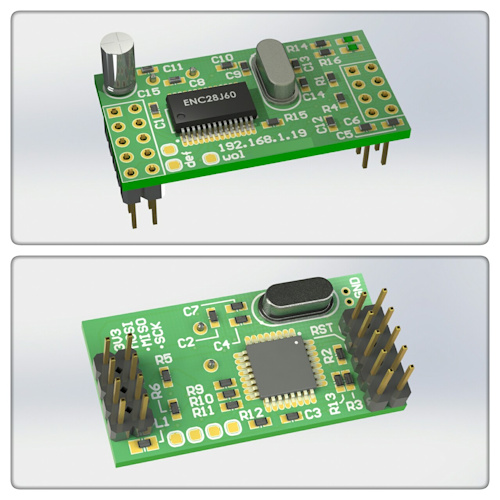
Model view (Altium)

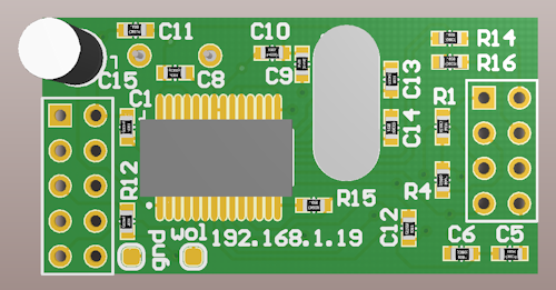
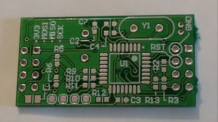
Already finished PCB:

In my device:


Main features
- "Bridge" always listens to port 23 and waits for a connection.
- Only one connection is possible at a time.
- There is support for ping
- Fully implemented TCP / IP
- Port speed from 2400 ... 115200
- There is support for RTS / CTS
- 3.3V power supply
The source for Atmeg328 itself
Schemes (PDF) and photos
Schemes and PCB painted in Altium ʻe, if necessary, write will send.
In general, I hope this will help someone to implement an external connection to their devices using Ethernet (TCP / IP).
Source: https://habr.com/ru/post/342424/
All Articles