Expansion of the menu functionality in nanoCAD 8.5: macros and LISP expressions

The nanoCAD menu files have a .cfg extension and a structure that differs from the menu structure ( * .mnu , * .cui , * .cuix ) of other CAD systems. Version 8.5 introduces support for macros, which can contain several commands and parameters, as well as LISP expressions.
Complex macro in the menu
For example, in the Notepad text editor, we write a drop-down menu MyTest.cfg from one item that creates a circular hole with a fixed radius of 500 at a fixed center point 700.600 in the drawing using the CIRCLE command. The dialog in the command line of such a macro is shown in Figure 1. The user must click on the menu item only once and no more data will be entered.
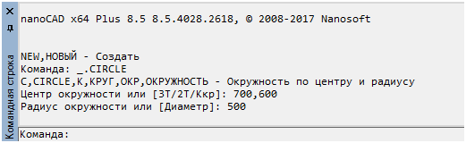
Fig. 1. Result of executing a complex menu macro
')
To implement such a menu, the menu and commands sections must be filled in the MyTest.cfg file:
[\] [\menu] [\menu\MyTest] Name=sMyTest [\menu\MyTest\MenuItem500] Name=s_R500 Intername=sMHole500 [\configman] [\configman\commands] [\configman\commands\MHole500] Weight=i30 CmdType=i1 Intername=sMHole500 LocalName=s_R500 DispName=s__R500 StatusText=s R500 ToolTipText=s R500 Keyword=s_.CIRCLE;700,600;500; IsUserCommand=f1 This file contains the description of the new MHole500 command with such a macro (the symbol s in front of it is the service one):
_.CIRCLE; 700,600; 500;
This macro contains the CIRCLE command and two parameters: 700,600 (coordinates of the center point) and 500 (radius value), which are separated by a semicolon (analogous to pressing Enter when working in the command line).
To simplify the loading of such a menu, apply the testcfg.package file , the name of which will be specified in the startup folder. To do this, go to the menu item Tools> Applications> Application Download , and in the Application Download / Upload window, click the Startup Portfolio Applications button (Figure 2).
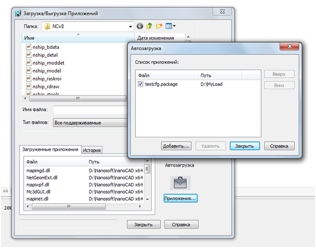
Fig. 2. Autoload testcfg.package using the portfolio
In the nested Startup window using the Add button, we add to the list of startup files the testcfg.package file, which will be placed in the D: \ MyLoad folder along with MyTest.cfg . In the testcfg.package file, which is an UTF-8 encoded XML file (this is important!), We will write the following:
<?xml version="1.0" encoding="utf-8" ?> <ApplicationPackage xmlns="hostModulePackage/v01" Name="Tests" > <Components> <ConfigEntry FileName="MyTest.cfg" FileType="CFG" /> </Components> </ApplicationPackage> Here, in the ConfigEntry tag, you should have information about the CFG file that needs to be loaded immediately after loading the main nanoCAD core (there should be several tags if you want to load several CFG files). For more information about .package files, see the article " Configuring the user interface when installing applications on nanoCAD Plus 8.5 ".
After exiting the windows Startup and Downloading / Unloading Applications and rebooting nanoCAD, our menu MyTest will appear in the menu bar (Fig. 3):
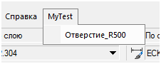
Fig. 3. MyTest in the menu bar
In the drop-down menu one item, it creates a circle of a fixed radius and a fixed center (Fig. 4):
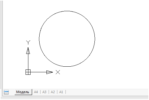
Fig. 4. Built circle
The macro we wrote is complex (consists of three parts). But implements a very simple option. Let's complicate the task: let the user specify the center point himself.
Pause in the menu
In version 8.5, pause processing in macros appeared. To illustrate this, copy the file MyTest.cfg to MyTest1.cfg , rename the command MHole500 to M1Hole500, and change the macro text in the Keyword parameter:
[\configman\commands\M1Hole500] weight=i30 CmdType=i1 Intername=sM1Hole500 LocalName=s_R500 DispName=s__R500 ToolTipText=s R500 Keyword=s_.CIRCLE;\500; IsUserCommand=f1 The macro has the form:
_.CIRCLE; \ 500;
Compared to the macro in the previous example, there are no center coordinates, but there is a backslash (\). This is a pause signal for user input (at this point, the CIRCLE command requests a center point).
Figure 5 shows how our macro looks like if you load the interface editor using the INTERFACE command (or using the menu item Tools> Interface> Interface Settings ), and in the window select the file MyTest1.cfg using File> Open .
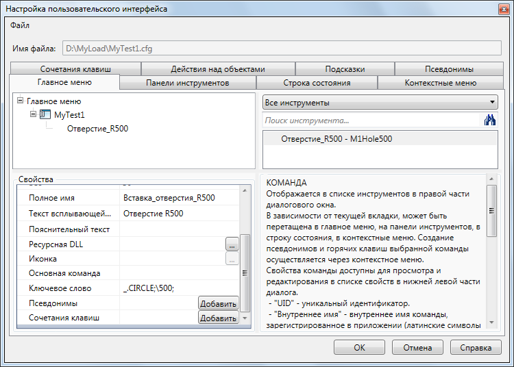
Fig. 5. Macro display with a pause character in the interface editor.
In the Properties pane, the macro text is shown in the Keyword parameter.
Important note. When saving menu files in the interface editor, they replace the main menu of the nanoCAD platform. You can return the previous main menu using the SETCONFIG command or manually edit the file “c: \ Users \\ AppData \ Roaming \ Nanosoft \ nanoCAD [x64] Plus 8.5 \ Config \ cfg.ini”.
Correct the testcfg.package file (you can add the MyTest1.cfg menu to it ). The approximate result of the macro (Fig. 6):

Fig. 6. The operation of the macro containing the pause character
LISP expressions in the menu
Processing LISP expressions on the command line is another step forward in nanoCAD 8.5. At the same time, it became possible to include LISP expressions in the menu macros.
For example, let's write another version of the menu MyTest2.cfg , but from three points that implement the creation of circular holes in a drawing using the CIRCLE command. Commands must be invoked via a LISP expression. Menu items will differ only in radius values (100, 200 and 300). In this case, the center point of the hole will be requested using a pause (LISP-symbol pause ). Along the way, we’ll slightly complicate the menu items by adding the standard CIRCLE command icon. System icons are in the file newbtns.dll , which is part of the software nanoCAD. The icon name matches the command name.
[\] [\menu] [\menu\MyTest2] Name=sMyTest2 [\menu\MyTest2\MenuItem100] Name=s_R100 Intername=sTHole100 [\menu\MyTest2\MenuItem200] Name=s_R200 Intername=sTHole200 [\menu\MyTest2\MenuItem300] Name=s_R300 Intername=sTHole300 [\configman] [\configman\commands] [\configman\commands\THole100] Weight=i30 CmdType=i1 Intername=sTHole100 LocalName=s_R100 DispName=s__R100 StatusText=s R100 ToolTipText=s R100 BitmapDll=snewbtns.dll Icon=sCIRCLE Keyword=s(command "_.CIRCLE" pause 100); IsUserCommand=f1 [\configman\commands\THole200] Weight=i30 CmdType=i1 Intername=sTHole200 LocalName=s_R200 DispName=s__R200 StatusText=s R200 ToolTipText=s R200 BitmapDll=snewbtns.dll Icon=sCIRCLE Keyword=s(command "_.CIRCLE" pause 200); IsUserCommand=f1 [\configman\commands\THole300] Weight=i30 CmdType=i1 Intername=sTHole300 LocalName=s_R300 DispName=s__R300 StatusText=s R300 ToolTipText=s R300 BitmapDll=snewbtns.dll Icon=sCIRCLE Keyword=s(command "_.CIRCLE" pause 300); IsUserCommand=f1 This file contains the description of three commands (THole100, THole200, THole300) that work by invoking LISP expressions with the command function. See how a macro with a LISP expression looks in the interface editor (in the picture in the title of the article, the menu MyTest2.cfg is shown).
After performing the above actions with the startup folder and rebooting nanoCAD in the menu bar, we will see our menu MyTest2 (Fig. 7):

Fig.7. MyTest2 with three menu items
There are three items in the drop-down menu; they create circles of three radii (Fig. 8):
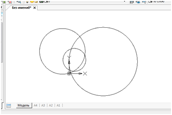
Fig. 8. The result of the three menu items
Transparent teams
In the nanoCAD system, some commands (for example, ZOOM or PAN) can be executed in transparent mode and they will not interfere with the execution of other previously launched commands. In version 8.5, the command call is implemented in transparent mode via the command line, preceded by their names by an apostrophe, by analogy with other CAD systems (Fig. 9):
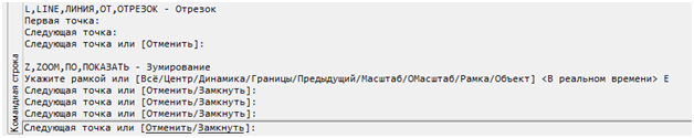
Fig. 9. Transparent 'ZOOM' command entered on command line
In the example above, during the LINE command, the command 'ZOOM with the parameter E (Show Borders) was called in transparent mode, after which the control was successfully returned to the LINE command.
It is possible to include transparent commands in the macro in the menu, for example:
Keyword = s_.CIRCLE; '_. ZOOM; _E; \ 400;
* .Cuix to * .cfg converter
When transferring custom menus from AutoCAD to nanoCAD, the CuixConverter.exe utility, ftp.nanocad.ru/habr/CUIX85/CuixConverter85.zip is very useful.
It reads the CUIX file and generates the corresponding CFG file. The syntax for using the converter (for example my.cuix ):
CuixConverter.exe [<path> \] my.cuix
<path> can be absolute or relative (according to Windows rules). If the path is not specified, the file should be in the current directory. As a result of the utility running, the file my.cuix.cfg will appear in the same folder <path> with the result of the conversion. This will save you from the hard work of writing CFG files manually or using the command Tools> Interface> Interface Settings .
To run the converter, a Windows command prompt window is required. It can be opened by typing cmd in the startup line. An example of working with the file MyMenu.cuix , which is located in the same folder as the converter files * .exe , * .dll (Fig. 10):
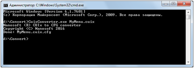
Fig. 10. Windows command line with the result of the converter
As a result of successful work, get the message Done: MyMenu.cuix.cfg .
Nikolay Poleshchuk
Source: https://habr.com/ru/post/342146/
All Articles