Automated workshop - 1. Example “Display”, development of OA and UA
Article 1 reviewed the internal structure of the Display example (laboratory version). Today's article describes the process of automatic development of the working version, focusing on how the choice of certain technical solutions was made. I will not repeat the contents of the mentioned article, limiting myself briefly to the statement of the problem.
Formulation of the problem
There is a b / w graphic display. Its video memory has a standard byte organization, in which each bit represents one pixel. Data output is streaming byte-filling the display video memory via a parallel interface or SPI using a protocol like:
')
- send the command Write_byte (coordinates_byte_ on_display)
- receive confirmation, after which you can send information
- data is transmitted by a continuous stream of bytes, sequentially, line by line filling the video memory
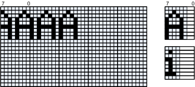
Text output must be done in different, not monospaced fonts.
but)
b)
at)
Figure 1. Display module requirements
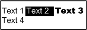
All characters in the same font height, but the font can be changed on the fly, in the process of outputting the same line. Similarly, attributes can be changed - bold, italic, underline. To control the parameters, esc-sequences are used , to which the control character '\ n', a line break, the text of one line can be displayed on several lines on the display. For example, the text:
"Text 1 \033[7m Text 2 \033[27m \033[1m Text 3 \033[21m \n Text 42" will be displayed as shown in Figure 1 (b)
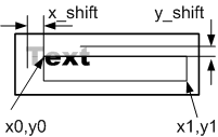
The text is displayed in the area bounded by the rectangle of Fig.1 (c), and may have an offset x_shift , y_shift . The coordinates of the output area are in pixels, the coordinates can be negative, which means going beyond the output area. Text that goes beyond the boundaries of the output area is cut off, Figure 1 (c).
User interface - function with prototype
void Out_text(int x0, int y0, int x1, int y1, int x_shift, int y_shift, char * Text); Start of development, obtaining requirements for automatic output of text blocks
The compilation of an automaton begins with decomposition into an operating and manager and can be repeated recursively — at each stage, an OA can be split into a pair of lower-level OA and its AA.
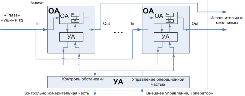
Figure 2. The recursive decomposition of the automaton on the operating and managing
Decomposition should be natural for the problem to be solved, and for this you need to try to portray the task visually, that is, to look at the problem in detail . Often, a competent representation of the process that needs to be carried out is tantamount to obtaining a solution to the problem in general, this is almost half the success in choosing OA.
Let me explain what I mean. As follows from the problem statement , the initial sequence of characters in the general case looks like: Text1 control1 Text2 control2 Text3 control3 Text4 control4 Text5 \ 0
where upN control esc-sequences, line breaks , tabs.
No additional effort is required to see in this scheme that there are monolithic text blocks separated by control sequences. Consequently, the overall task is divided into the stage of splitting the initial sequence into blocks and the output of these blocks.
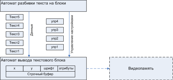
Figure 3. Initial partition
This is the simplest case, such a partitioning of the original task was suggested by itself, in other cases it is not so obvious, therefore in the Practicum cycle I will pay attention to a substantive look at the original problem, giving advice using examples.
An important place is occupied by the communication between the parts, if it can be made such that the alteration of one of the levels will not affect other levels, it will be a huge plus. Each text block is characterized by coordinates of the text block x_block, y_block (relative to the output window). Since the font and attributes (inverse or not, flashing, bold, italic, underline, and so on) may remain unchanged, you should not provide each text block with unnecessary information, but make a separate channel ( automatic output method of text blocks ) for attribute management. Such a partitioning scheme and such communication between the parts makes it possible to implement the OA of the automatic output of text blocks in the most convenient way, without touching the other parts, which has been demonstrated: for the OA A1 scheme and OA A2 scheme, the general partitioning scheme remains the same same
Thus, the requirements for the automatic output of text blocks are as follows.
Automatic text block output
Requirements for automatic output of text blocks can be represented graphically.
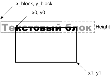
Figure 4. Requirements for automatic output of text blocks
Each of the text blocks no longer contains control sequences within itself and is displayed with unchanged attributes from the position x_block, y_block to the end of the block or to the end of the screen. The values of x_shift, y_shift affect the location of the whole group of blocks and, when displaying a separate block, are already compensated for the value of x_block, y_block . The upper right corner of the text box is relative to the upper right corner of the output window, the height is equal to the font height, and the width is equal to the width of the text or the output window if the text does not fit entirely.
Machine Design as a Process
Shown in fig. 2, the recursiveness of decomposition does not continue infinitely, in our case it is two levels of splitting. For many tasks there will be the same pair of levels, or even one. A large multistage characteristic is not for modules, but for systems.
After this, a detailed study of the indivisible pair of OA + UA, the lower level pair and its software implementation, which occur from the bottom up , from OA to UA, occurs. This is dictated by the fact that usually the lowest level is directly tied to the actuators, which puts us within certain limits and limits the possibility of "maneuver" and at the same time determines the degree of efficiency, while higher levels are more flexible in this regard, and they follow from the implementation of the underlying automata. These “frames” are sometimes groped in the process of development, and during the initial analysis and decomposition they are hidden by the “fog of war”. This illustrates the importance of communication between the parts, which I mentioned above, which play the role of “watertight bulkheads”, allowing us to limit ourselves to changing only individual modules, and not the entire stack of automata.
The process of automatic development of an indivisible pair of OA + UA iterative:
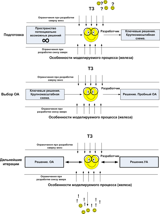
Figure 5. The iterative process in automated development
In an iterative way, large projects are developed, on which collectives work, and the same form of work organization is suitable for individual use. In this case, we are not talking about formalities. An individual iterative design process does not imply scheduled meetings of participants who need to share results and report, the developer is one. Iteration is just a line of thought flow. An individual iterative design process is a design process of OA and UA, in which each iteration is “doped” by OA and “pulled” by UA. As mentioned repeatedly, effective design is first and foremost an effective OA, so development begins with it.
OA model selection
The study of OA begins from the lowest level. Since data output to the display is streamed byte-filled by video memory through a communication channel, it is supposed to use a scheme with an intermediate line buffer in which the “fingerprint” of each character (glyth) is placed, and after the entire text block is output, the line buffer content is discarded into the display streams of bytes, horizontal lines in the entire width of the text and one pixel in height.
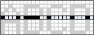
Figure 6. Long lines of stream output from line buffer to video memory.
The overall output scheme looks like:

Figure 7. General output model
In the implementation of A2 (recall that the general output model is the same, Fig. 3), the operating automatic output to the line buffer is a very universal, but because of this low-performance OA of arbitrary pixel transfer. The cyclic consumption of this variant is O (W * H) , i.e. proportional to the character area.

Figure 8. An arbitrary pixel transfer automaton.
But how to get high-performance OA? The natural solution is to transfer the bits immediately in groups. It would be best to transfer the characters with an operation that at once copies the entire rectangular footprint array from the character generator to the line buffer, the cyclo-consumption of this variant is proportional to O (1) . However, there are no such commands. Copying a character to the string buffer in rows is the most efficient way available.
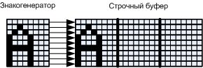
Figure 9. The optimal transfer scheme underlying OA for A1
The line-by-line output of characters from the character generator is technical solution No. 1, it provides the foundation for future efficiency and it is already possible to give first estimates: the cyclo-consumption of such an option will be proportional to the number of lines in the O (H) symbol, which, by the way, is shown in the previous article, fig. 14.
It should be noted that the width of characters in pixels is not proportional to the width of a byte, and the text block itself may not start from a byte boundary. In this case, it is impossible to copy the contents of the character generator bytes into bytes, a preliminary shift of each character line is required.
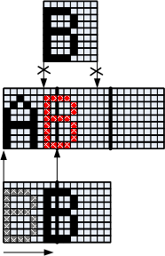
Figure 10. Explaining the need to shift the glyph before outputting to the line buffer
From the illustration of fig. 10 shows that several characters can be included in each byte of the string buffer. In order for several characters to get into one byte not to overwrite each other, the data of the shift register are not copied, but superimposed on or . However, this operation requires pre-cleaning the buffer, which translates into overhead, which will generally be proportional to the size of the line buffer in bytes, and its size is proportional to the number of lines in the font. Fig. 11 confirms this dependence
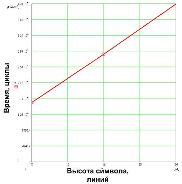
Figure 11. Dependency of Total Overhead on the number of lines in the font, for the variant with string buffer cleaning
Summarizing the subtotal, the working scheme is as follows:
- the data from the character generator is copied to the shift register - one character line per iteration.
- there they shift to the
Current_shiftpixels - the already shifted contents of the register are superimposed on or on a certain portion of the line buffer, which is addressed by the
Current_bytepointer. - line buffer must be cleared in advance.
- this is repeated for all lines of the symbol, after which both
Current_shiftandCurrent_byteincremented by formulas.
Formula 1
Current_byte = (Current_byte + (Current_shift + Width)) >> 3; Current_shift = (Current_shift + Width) & 0x7; 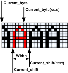
Figure 12. Basic OA text block output model
From formula (1) in particular, it follows that 7 positions for the variable Current_shift (shift value) is the maximum value, any shift by a large amount is limited modulo 8. For example, 12 bits are converted into a shift by 4 pixels and unloading the shift register by 1 byte to the right.
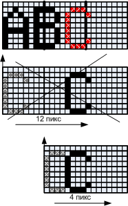
Figure 13. Modulation-shift limitation 7
It was a preparatory iteration, the choice of key, strategic decisions. In this variant, the solution that is working, itself suggested itself, but there are cases when the subject image of the conditions of the problem does not even hint at what kind of operating machine to process them. In this case, the conditions of the problem can be subjected to mathematical processing, and the solution is not the original problem, but a mathematically identical, but more convenient one (in later articles I will explain this with examples). For serious tasks, you may even have to consider a number of solutions and make technical estimates of speed and other resource costs, for which you may even need to go further along the described instructions and perform one or two subsequent iterations. In any case, such an approach makes it possible to choose the optimal solution in a reasonable time.
Based on the chosen strategic decision, OA is being developed. In OA, I remind you, everything that is connected with the direct transfer and transformation of data goes, and in UA, what will be necessary for the operation of OA.
Iteration 1. Source OA
The operating machine is a semi-finished product, it optimally performs the required operation with any valid parameters. In this case, the UA is the parameterization and the start of the OA. Such a structure gives high flexibility and means in particular that the OA itself does not change the contents of Current_shift and Current_byte . It receives a ready-made set of parameters for performing all the above operations. To find out what other parameters are needed, consider how exactly OA will work. I have already written above about the importance of a visual image of the phenomenon that is being modeled. It should be added that it is important to depict not only the ideal case, but also “not convenient” variants that are associated with boundary conditions. This will allow to avoid wrong decisions, with the subsequent alteration, perhaps, of all previously accumulated. I focus on this attention, because it is a psychologically difficult moment - to portray the simulated phenomenon from the most difficult point, as if complicating the task for myself. However, the complexity of the problem being solved is an objective thing, and it does not depend on whether you close your eyes for uncomfortable moments or not, and the only thing you can influence is the complexity of solving this problem, and it will be as low as possible if you look for a solution from the outset understanding how difficult moments have to face. This approach shifts the resource development of the program from the debugging stage (when dealing with a bunch of implemented modules) to the design phase (when dealing with a blank canvas).
All characters are of different widths, so you need a parameter - the number of bytes loaded for each character string:

Figure 14. The parameter bytes_For_load
After loading each line of the character needs to be shifted. It should be noted that the shift occurs for different microcontrollers in different ways. ARMs have an effective bitwise shift mechanism for up to 32 bits per cycle, and this shift can simply be added as an option to other commands, such as arithmetic. In the case of msp430, the best shift command is: 16 bits per position. However, the general scheme does not change from this, just note that for processors with a shift of 1 position (msp430), you can use a more efficient scheme of shift through assembler inserts, the command "shift through the transfer flag." As an extreme option (this applies not only to the Display but in general to different OA), you can write OA on a macro assembler, which will deploy relatively simple code into arrays of assembler instructions. Perhaps an assembler implementation is not needed, I mentioned this to indicate that there is an additional "trump card", ways to improve the "Display" module, if necessary. It does not require alteration of the AA, because it is part of the concept of OA and UA families described in the previous article.
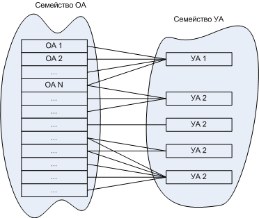
Figure 15. Families OA and UA
Over time, the families of operating machines will be replenished with a variety of machines, which will allow for the use of an effective semi-automated search among them, which will become a convenient development tool. But, by the way, for our example, the OA and UA families are not needed for “manual” automaton design, so I’ll focus on one of the options chosen.
Shift need all bytes included in the line. The shift direction is logical to take in such a way that the number of positions for the shift is minimal, however, practical experience says that uniformity in carrying out operations is of considerable value, so the option of shifting to the right will be considered, and it can already be implemented so that it is actually shorter. the side.
At a certain amount of shift, the number of bytes that need to be shifted may increase by another byte compared to the number of bytes that need to be loaded.
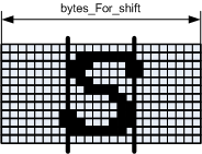
Figure 16. Parameter bytes_For_shift
After the shift, the contents of the shift register are dropped into the string buffer. At first glance, the number of bytes for the output should coincide with the number of bytes for the shift, but if you imagine that the leftmost pixel of this character protrudes to the left of the screen edge, then the number of bytes for the output will not match the number of bytes for the shift.

Figure 17. Parameter bytes_For_out
The general scheme of OA, therefore, will be approximately as follows:
class tShift_buffer { public: void Load (u1x *Source, int Bytes_amount); void Shift(int Bits_amount, int Bytes_amount); void Out (u1x *Destination, int Bytes_amount); }; //////////////////////////////////////////////////////////////////////////// // void Out_symbol() { // for(int y = 0; y < Height; y++) { u1x * Glyph_line = Current_font->Image_for(* Text) + y * bytes_Width; Shift_buffer.In (Glyph_line, bytes_For_load); Shift_buffer.Shift (Current_shift, bytes_For_shift); Shift_buffer.Out (&String_buffer [y][Current_byte], bytes_For_out); }// for(int y = y0; y < Height; y++) }// void Out_symbol() It is obvious that the effectiveness of this OA directly depends on how the operations with the shift register are implemented. On this further, in the meantime, it seems that there is nothing difficult to implement them effectively.
Now you can start drawing up a model of the control machine. Further detailing of OA can now lead to a dead end. This is due to the fact that the choice of extremely effective OA can lead to exorbitant overhead costs in UA and, accordingly, to the inefficiency of the whole scheme. In addition, developing a ready-made OA scheme and not even having a UA model, you will have to keep this model in mind, which can simply lead to conflicting requirements that cannot be implemented. And finally, the most important thing: in order to understand how suitable the OA model from the previous listing is, you need to look at the whole process from a height, so to speak, bird flight.
Iteration 1. Source UA
So, the initial implementation of the AA is required, which will allow to detail the OA, estimating in the course of detailing what this will result in from the point of view of the AA. The development of UA is inseparable from the development of OA due to the fact that the first controls the parameters of the second. In developing the UA, we do not stop discussing OA and its parameters, but on the contrary, we add the calculation of these parameters and their initial values.
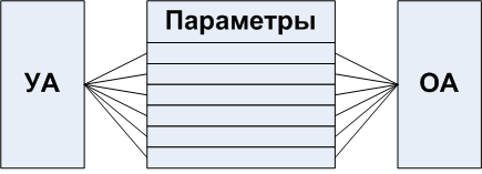
Figure 18. The close relationship of OA and UA
Accordingly, it would be nice to keep records of the parameters so that none of them are un-initialized or without control by the UA, as well as that their number does not grow beyond measure.
Table 1. Parameters for OA operation
variable parameter | formula |
width | loading from character generator |
current_byte, current_shift | current_byte = (current_byte + (current_shift + width)) >> 3; current_shift = (current_shift + width) & 0x7; current_byte 0 = 0; current_ shift 0 = x_block & 0x7; |
bytes_for_load, bytes_for_shift, bytes_for_out | further defined |
Such a table is constructed as the automaton is drafted on a draft, as an auxiliary one. However, returning to the compilation of some “generic, universal automaton template” described in the “ Looking to the Future ” chapter of the previous article, such a table can be used to describe UA and OA in the form of mutual export / public announcements with the possibility of combining those of them which match the parameter sets that will be used in computer-aided design systems.
Trial version va.
If it was required to output infinite text to an infinitely long line buffer, starting at position 0, then the UA would be as follows
uchar * Text; uchar String_buffer[y_string][x_max /* 0.Infinity */ ]; //////////////////////////////////////////////////////////////////////////// // void Out_text_block(uchar * Text) { Current_shift = Current_byte = 0; while(1) { Witdh = Current_font->Width_for(* Text); bytes_For_load = (Width + 7) >> 3; bytes_For_shift = (Width + Current_shift + 7) >> 3; bytes_For_out = bytes_For_shift; Out_symbol(); Current_shift = (Current_shift + Width); Current_byte = (Current_byte + Current_shift) >> 3; Current_shift &= 0x7; Text++; } }// void Out_text_block(uchar * Text) However, we are dealing with real text of finite length, moreover, having an initial shift relative to the output window, and this text may not fit in the output window either from above or below, or from left and right.
The case where the text protrudes beyond the edge of the output window from the top or bottom.
Accounting for the constraints below and above is simpler than on the right and left, so I'll start with it. It may be that the height of the character is wider than the output bar, or the initial shift of the text may result in some of the text protruding from above, or below, or immediately above and below.
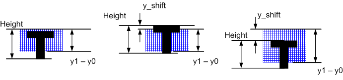
Figure 19. Vertical oversized text variations.
From the point of view of OA, this behavior is implemented simply. It is enough to modify the “VERTICAL CYCLE” shown in the listing, which goes through the lines from 0to Height, so that it goes through the lines from Start_lineto End_line, where Start_lineis the number of the upper line of the glyph that goes into the buffer, End_lineis the number of the first line (below) that no longer falls into the range of values being sorted. That is, for a 6x9 character that completely falls into the buffer End_line = 9.
First determinedStart_line
if(y_block < y0) { Start_line = y0 - y_block; } else { Start_line = 0; } if( Start_line >= Height) // , End_linesearched based on value Start_line. if( (y1 – y_block) >= Height) { End_line = Height; } else { End_line = y1 – y_block; } The case where the text protrudes beyond the edge of the output window to the right or left.
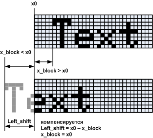
Horizontally, the situation is more complicated due to the byte grouping of columns. Block start coordinate - x_block. The value is x_shiftcompensated, you can not remember about it.
20.
x_block > x0 , , , , – . x_block < x0 -, . . 20, . , Left_shift , .
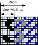
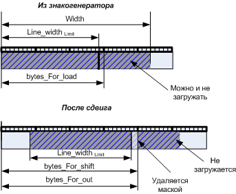
« » . 21.
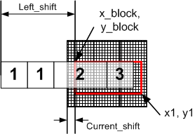
21. .
Left_shift , ( 1 ). .
, ( 2 ). ( 3 ), 2 ( ) , 3 . , — . , , .
, 2 3 .
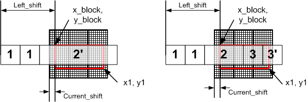
22.
, 2, 2', 3 3' . , , . , . , . ( ) .
1. . Continuation
left_shift | if ( x _ block >= x 0) |
, , . 23

23.
As I noted earlier, in addition to the description of the automaton, the state diagram is at the same time a scheme for describing the algorithm, an alternative to graph-schemes. According to it, it is elementary to make a software implementation. The colors indicate the text of the program corresponding to the states.
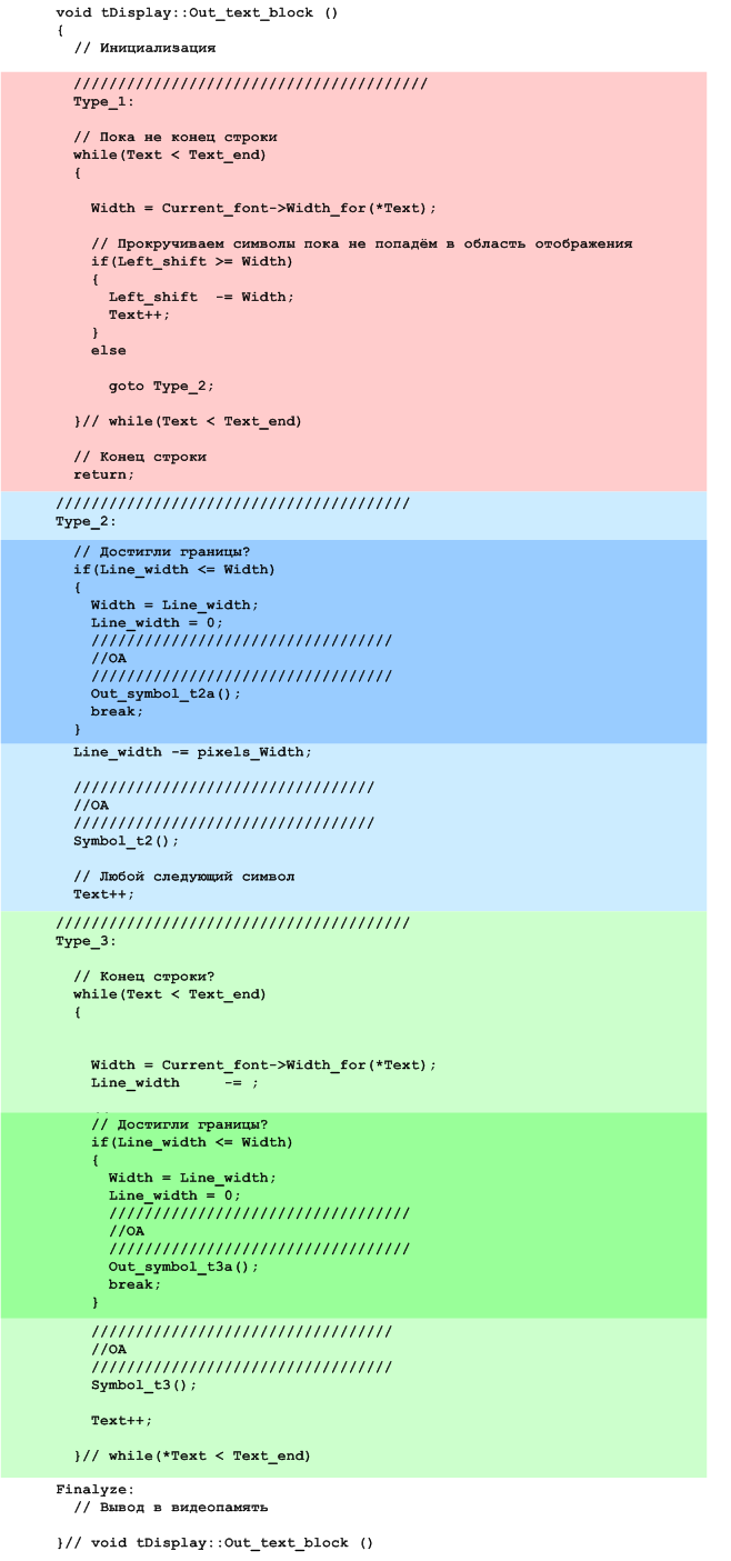
The parameter
Line_widthindicates whether the end of the output window is reached or not.Table 1. Parameters for OA operation. Continuation
variable parameter | formula |
line_width | line _ width = line _ width - width ; |
Making a commit
This is not a working application yet, instead of OA, caps are used that are displayed in the debugging Memo: symbol, width, type according to our classification (2.2a, 3.3a). For type 2 / 2a characters, the offset value is additionally displayed
Left_shift.The situation is generally understandable. The next task is to obtain, in a first approximation, the working module OA.
Iteration 2. OA
There are symbols of three types 1, 2 and 3 and two subtypes 2 'and 3'. It is logical to use for their output specialized for each type of OA.
Characters are completely out of the output window.
Those characters that are not completely in the display area due to the left shift, are shown in figure 1, they are easiest to handle, just scrolling all characters that do not fall into the display area.
// , while(Text < Text_end) { Width = Current_font->Width_for(*Text); // if(Left_shift >= Width) { Left_shift -= Width; Text++; } else goto Type_2; }// while(Text < Text_end) Characters fit in the entire output window.
Type 3 is the main character type that has already been described. For its processing needs parameters
Current_byte(known from the previous symbol) Current_shift(known from the previous character) bytes_For_load, bytes_For_shift, bytes_For_out.
Figure 24. Character type 3 parameters
Since the actual calculations take place in an algebraic ring, edge effects cannot be avoided.
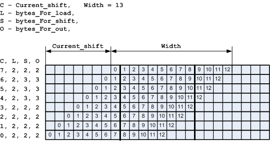
Figure 25. Explanation of the calculation of parameters for type 3
Using the illustration of Fig. 25 it is easy to make formulas for calculating parameters.
bytes_For_load = (Width + 7) >> 3; bytes_For_shift = (Width + Current_shift + 7) >> 3; bytes_For_out = bytes_For_shift; Current_shift_next = (Current_shift + Width) & 0x7; Current_byte_next = Current_byte + ( (Current_shift + Width) >> 3 ); Characters protruding only on the right.
but)
b)
Figure 26. Character type 3a parameters
Magnitude this is the rest of the line at the moment when the event occurs The boundary of the output window is reached , that is, the type 3a symbol does not fit on the screen entirely
Source: https://habr.com/ru/post/342048/
All Articles