Using the KOMPAS-3D API → Lesson 6 → Construction of a circular arc
We continue the cycle of articles on working with the CAD API KOMPAS-3D Sergey Norseev, an engineer-programmer of the All-Russian Scientific-Research Institute “Signal”, the author of the book “Development of applications for KOMPAS in Delphi”. C ++ Builder is used as the medium. In previous lessons on the API KOMPAS Basics and Drawing Design, we proceeded from the fact that KOMPAS is not running, in the Lesson Correct connection to KOMPAS we checked for the presence of already running KOMPAS and connected to it. In the lesson the Main inscription was disassembled, how to fill the main inscription of the drawing. In the last lesson, Graphic primitives, we began to draw the first geometric shapes. This article discusses various ways to build a circular arc. In COMPASS, it can be built in three different ways. We will cover them all.

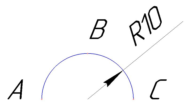
First, let's decide what we will build. For example, I propose to take a semicircle with a radius of 10 mm centered at the point with coordinates (100, 100) . This arc is shown in the figure below.
(The picture is clickable).
')
A, B and C are auxiliary points that will be useful to us when describing various ways to construct an arc.
The first method is based on the fact that you know the coordinates of points A, B and C , but the coordinates of the center are unknown. To build an arc on three points, use the ksArcBy3Points method of the ksDocument2D interface. Below is its prototype.
Line styles were discussed in a previous article in the series .
In case of success, the method returns a pointer to the constructed arc, and in case of error, the value is zero .
To build our arc you need to decide on the coordinates of the points. So, point A has coordinates (90, 100) , point B (100, 110) , point C (110, 100) . With such source data, the ksArcBy3Points method call should be made as shown below.
How to get a pointer to the ksDocument2D interface was described in previous articles in the series .
This method is based on the fact that you know the coordinates of the center of the arc and the angles of its ends. To construct an arc using this information, the ksArcByAngle method of the ksDocument2D interface is used . Below is a prototype of this method.
With the parameters xc , yc , rad and style , I think everything is clear. There should be no questions with them.
The parameters f1 and f2 define the angles ( in degrees ) between the straight lines passing through the center of the arc and its end points, and the horizontal line. These angles are shown in the figure below.
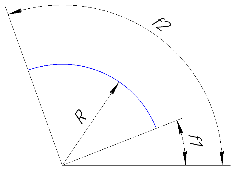
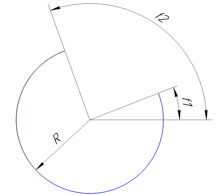
Now about the direction parameter. It sets the direction in which the arc should be drawn. If it is equal to 1 , then the arc is built counterclockwise, if it is equal to -1 , then the arc is built clockwise. For example, the arc shown in the figure above is drawn counterclockwise, and the figure below shows an arc constructed with the same parameters, but clockwise.
If successful, the ksArcByAngle method returns a pointer to the constructed arc, and in case of error, the value is zero .
Let us return to our task of constructing an arc. To render it counterclockwise, the angles must be set as follows: f1 = 0 , f2 = 180 . To draw the same arc clockwise, the angles need to be swapped (f1 = 180, f2 = 0) .
The arc construction code is shown below.
This method is based on the fact that you know the coordinates of the center of the arc and the coordinates of the end points of the arc. To construct an arc using this information, the ksDocument2D interface's ksArcByPoint method is used. Below is a prototype of this method.
This method is very similar to the ksArcByAngle method discussed earlier. The only difference is that the end points are not defined by angles, but by coordinates.
If successful, the ksArcByPoint method returns a pointer to the arc, and in case of error, zero .
Below is the code to call this method to build our arc.
The attentive reader probably noticed that the parameters of the ksArcByPoint method are redundant. Why? Is there really a bug creators API? Not really. You just need to correctly understand the purpose of the points (x1, y1) and (x2, y2) . According to KOMPAS documentation:
x1, y1 - coordinates of the starting point of the arc,
x2, y2 - coordinates of the end point of the arc.
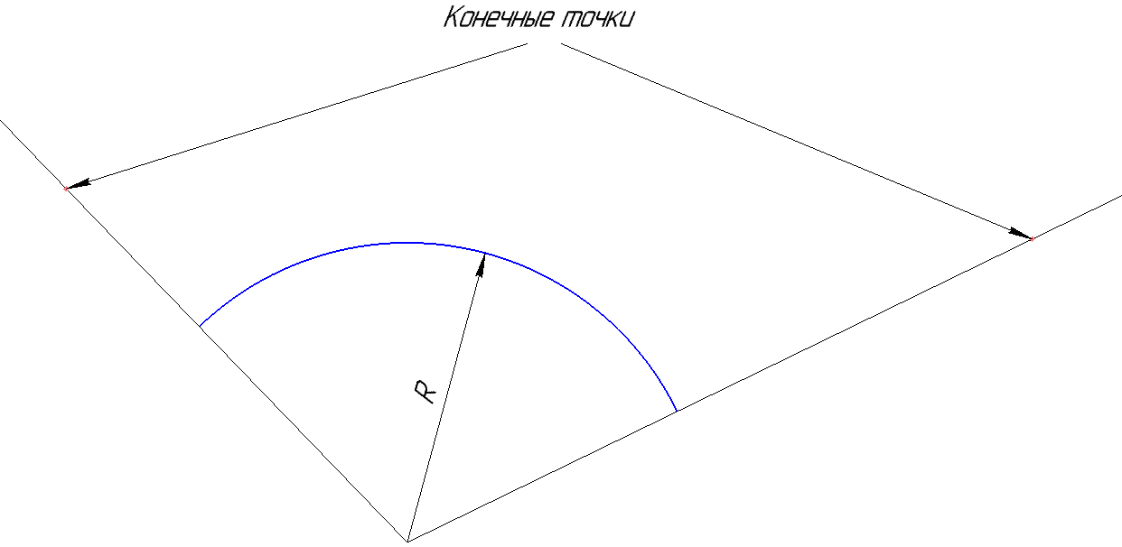
Such an incorrect description creates confusion. In fact, the points (x1, y1) and (x2, y2) may not belong to an arc. They specify not the position of the end points, but the orientation of the vector on which they are located. And the beginning of this vector is in the center of the arc. The figure below explains this more clearly.
On this basis, the arc we are considering can be constructed using the code below.
Note: the end points do not coincide with the points A and C , but the arc is still built correctly.
Conclusion
In this article, we looked at various ways to build a circular arc. Which of them to use, decide for yourself. But I think that your decision will be determined by the information about the arc that you have at a given time.
To be continued, stay tuned to the blog.
 Sergey Norseev, author of the book “Development of applications for KOMPAS in Delphi”.
Formulation of the problem
First, let's decide what we will build. For example, I propose to take a semicircle with a radius of 10 mm centered at the point with coordinates (100, 100) . This arc is shown in the figure below.
(The picture is clickable).
')
A, B and C are auxiliary points that will be useful to us when describing various ways to construct an arc.
By three points
The first method is based on the fact that you know the coordinates of points A, B and C , but the coordinates of the center are unknown. To build an arc on three points, use the ksArcBy3Points method of the ksDocument2D interface. Below is its prototype.
long ksArcBy3Points ( double x1, // double y1, double x2, // double y2, double x3, // double y3, long style);// Line styles were discussed in a previous article in the series .
In case of success, the method returns a pointer to the constructed arc, and in case of error, the value is zero .
To build our arc you need to decide on the coordinates of the points. So, point A has coordinates (90, 100) , point B (100, 110) , point C (110, 100) . With such source data, the ksArcBy3Points method call should be made as shown below.
Document2D->ksArcBy3Points( 90 , 100, // 100, 110, // B 110, 100, // C 1); //C How to get a pointer to the ksDocument2D interface was described in previous articles in the series .
Centered and corners
This method is based on the fact that you know the coordinates of the center of the arc and the angles of its ends. To construct an arc using this information, the ksArcByAngle method of the ksDocument2D interface is used . Below is a prototype of this method.
long ksArcByAngle ( double xc, // double yc, double rad, // double f1, // double f2, short direction, // long style); // With the parameters xc , yc , rad and style , I think everything is clear. There should be no questions with them.
The parameters f1 and f2 define the angles ( in degrees ) between the straight lines passing through the center of the arc and its end points, and the horizontal line. These angles are shown in the figure below.
Now about the direction parameter. It sets the direction in which the arc should be drawn. If it is equal to 1 , then the arc is built counterclockwise, if it is equal to -1 , then the arc is built clockwise. For example, the arc shown in the figure above is drawn counterclockwise, and the figure below shows an arc constructed with the same parameters, but clockwise.
If successful, the ksArcByAngle method returns a pointer to the constructed arc, and in case of error, the value is zero .
Let us return to our task of constructing an arc. To render it counterclockwise, the angles must be set as follows: f1 = 0 , f2 = 180 . To draw the same arc clockwise, the angles need to be swapped (f1 = 180, f2 = 0) .
The arc construction code is shown below.
Document2D->ksArcByAngle( 100, 100, // 10, // 0, 180, // 1, // 1); //C Center and end points
This method is based on the fact that you know the coordinates of the center of the arc and the coordinates of the end points of the arc. To construct an arc using this information, the ksDocument2D interface's ksArcByPoint method is used. Below is a prototype of this method.
long ksArcByPoint ( double xc, // double yc, double rad, // double x1, // double y1, double x2, // double y2, short direction, // long style); // This method is very similar to the ksArcByAngle method discussed earlier. The only difference is that the end points are not defined by angles, but by coordinates.
If successful, the ksArcByPoint method returns a pointer to the arc, and in case of error, zero .
Below is the code to call this method to build our arc.
Document2D->ksArcByPoint( 100, 100, // 10, // 110, 100, // C 90 , 100, // A 1, // 1); // The attentive reader probably noticed that the parameters of the ksArcByPoint method are redundant. Why? Is there really a bug creators API? Not really. You just need to correctly understand the purpose of the points (x1, y1) and (x2, y2) . According to KOMPAS documentation:
x1, y1 - coordinates of the starting point of the arc,
x2, y2 - coordinates of the end point of the arc.
Such an incorrect description creates confusion. In fact, the points (x1, y1) and (x2, y2) may not belong to an arc. They specify not the position of the end points, but the orientation of the vector on which they are located. And the beginning of this vector is in the center of the arc. The figure below explains this more clearly.
On this basis, the arc we are considering can be constructed using the code below.
double xc = 100; double yc = 100; Document2D->ksArcByPoint( xc, yc, // 10, // xc+1, yc, // xc-1, yc, // 1, // 1); // Note: the end points do not coincide with the points A and C , but the arc is still built correctly.
Conclusion
In this article, we looked at various ways to build a circular arc. Which of them to use, decide for yourself. But I think that your decision will be determined by the information about the arc that you have at a given time.
To be continued, stay tuned to the blog.
Sergey Norseev, author of the book “Development of applications for KOMPAS in Delphi”.Source: https://habr.com/ru/post/342032/
All Articles