Tale about resistors and neon
Calculation of DC circuits on the fingers, or let's assume the DAC for the ternary logic
But for starters neon, what kind of Russian does not love them?
So, again I am with my triple glands, but in this article they act as a background, today there is an article about resistors. I had a few handkerchiefs in which I could insert gas discharge lamps like IN-12 or IN-15, but I didn't want to make the clock :)
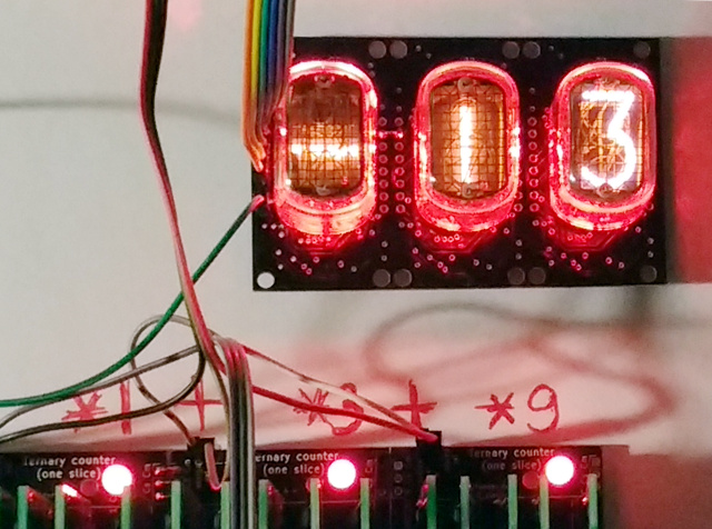
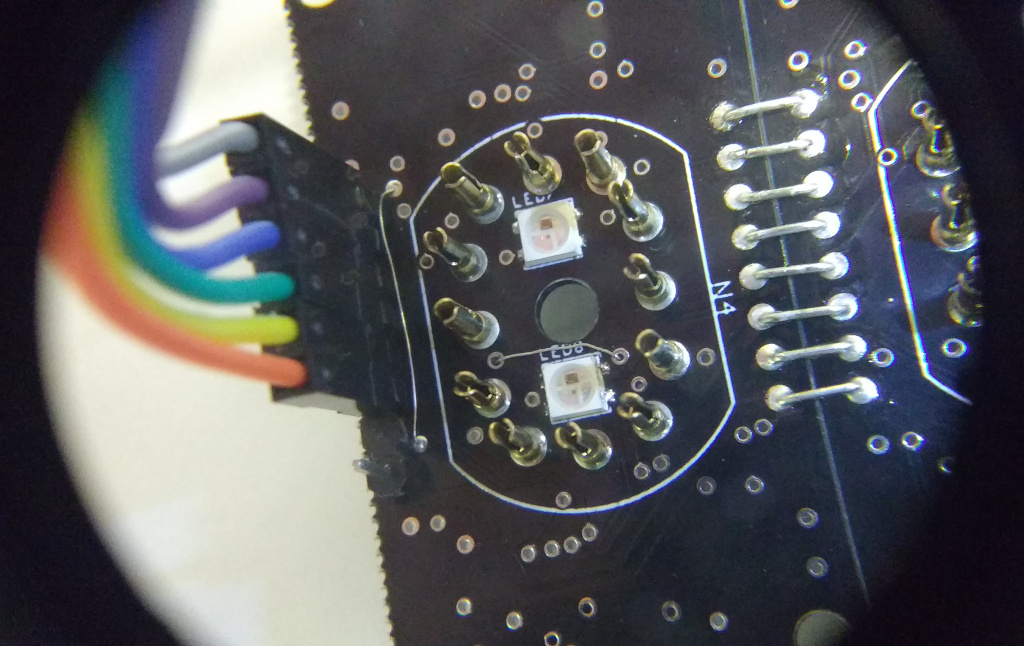
The simplest scarves carry a pair of sk6812 LEDs to illuminate the balloon, a dozen transistors and their 595e shift registers. This is how a handkerchief looks like, carrying one lamp on itself, but at the same time they can be assembled into a long sausage to achieve the desired number of lamps:
')
Thanks ikaktys for the help! At the same time with the neon-women I threw up and soldered the ternary counter, which I had previously collected on the breadboard and described in detail .
I remind you that my ternary counter uses a balanced ternary number system, which is represented by three voltage levels (-5, 0 and 5 volts). Its state is indicated by two-color LEDs: red is a negative value, extinguished is zero, and green is a positive value.
It would seem that this is quite enough, why are there neonas? One of my friends, who is very sincerely interested in where the threefold path will lead me, turned out to be color blind! Thus, I had to think about an alternative to two-color LEDs. And here the neon box lies, and the decimal display is convenient.
Cross the horror and hedgehog, or how to make friends binary and ternary logic
Since I have, as is known, arduino of the brain, I manage the neonks with the help of arduin. That is, the neon driver works on binary logic, and I need to output information based on the ternary one. I was too lazy to gossip about the decoders, and since I already have an arduin, I decided to simply get the ternary signal into the ADC of the arduin, good, it has more than enough free legs. Then we just look at which third of the ADC area is the current line, and this will give us the threefold value inside the arduin.
Only one bad luck: the Arduin wants to measure the analog signal between the ground and five volts, and the ternary signal has a variation from minus five to five. By the way, it is necessary to measure arduine voltage from -5 to 5 V in other areas. For example, recently I needed to measure the current in the DC motor windings, and the hall sensor gave me a signal from -5 to 5.
That is, I need to scale the voltage level twice and move it to the positive area. The easiest way to do this is to hang each ternary line according to such a resistor divider:
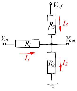
The ternary signal enters Vin (from -5 to +5 V), the Arduin power is Vref (5 V), and the Vout starts up on the arduine's ADC. This raises the question of how to select the necessary resistor values so that Vout is located in the working area of the ADC (from 0 to 5 V).
Probably, there are people who can do this almost in the mind, but I don’t belong to them, and I know physics only at the school level. My secret knowledge is that you do not need to lick the outlet. But I can read, therefore, after reading Wikipedia, we arm ourselves with Ohm’s law, Kirchhoff’s law and the ability to solve linear equations.
First, let's set the task as follows: knowing the resistances R1, R2 and R3, as well as the voltages Vref and Vin, find the current flowing through each resistor, and at the same time the output voltage Vout.
Let us arbitrarily choose the direction of current flow (indicated by the arrow) through each resistor. If we “made a mistake” with the choice of direction, then just the current strength will turn out to be negative.
Then we write the Kirchhoff's law for the chain node (the one that is marked with a bold black dot in the diagram): the sum of the flowing currents equals the sum of the incoming currents, that is, I1 + I3 = I2.
Then the second Kirchhoff rule for a closed loop tells us that the sum of the voltages across the resistors is equal to the total emf of the loop.
We can choose two circuits, one with a common voltage Vref, the second with a voltage Vin. We write all three equations:

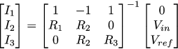
Let's rewrite the same system in a matrix form, I’m lazy to solve it with my own hands, and in the software for symbolic matrix calculations it is obviously more convenient:

And then the desired currents I1, I2 and I3 can be found by reversing the 3x3 matrix of our system:
Then the output voltage Vout can be found through the newly found I2:

This is fine, but in general our task is not to find Vout from known resistances and Vin, but on the contrary, knowing the range of Vin, choose resistance so that Vout fits between zero and Vref.
Let's substitute 5 volts of arduin power supply instead of Vref in our equations, choose arbitrarily R1 resistor at 100kOhm (we have the same voltage divider, so we can choose one of the resistors ourselves). Then we write down two equations: for Vin = -5, Vout should be equal to zero, and for Vin = 5, Vout should be equal, for example, 4.9 V. That is, we got the following system of equations, I didn’t simplify anything specifically:

In general, a polynomial equation is obtained; you can count it by hands, but why? I will consider it in sage, here you can execute the code below:
var("R1,R2,R3,Vin,Vout,Vref") A=matrix([[1,-1,1],[R1,R2,0],[0,R2,R3]]) b=matrix([[0],[Vin],[Vref]]) I=(A.inverse()*b).simplify_full() I2=I[1][0] eq1=(4.9==(I2*R2).substitute(Vin= 5,Vref=5,R1=10^5)) eq2=(0 ==(I2*R2).substitute(Vin=-5,Vref=5,R1=10^5)) solve([eq1,eq2],R2,R3) Here is the output of the solve command:
[[R2 == 0, R3 == 0], [R2 == 2450000, R3 == 100000]]Our resistors must have strictly positive values of the ratings, so we discard the obviously impossible answers. Total, the solver tells us that if we choose R1 = R3 = 100 kΩ and R2 = 2.45 megaoma, then when powering Vref = 5 V, the input voltage range Vin = [- 5 V, + 5 V] will be displayed in the Vout node in range [0 V, 4.9 V]. Hooray!
A question for attentive readers: why did I choose the output range of 0-4.9 V, and not 0-5 V?
Here is the code I use:
Hidden text
#define F_CPU 16000000L #include <avr/io.h> #include <avr/interrupt.h> #include <util/atomic.h> #include <util/delay.h> #include <stdlib.h> #include <stdio.h> #include <avr/pgmspace.h> // PSTR /////////////////////////////////////////////////////////////////////////////////////////////////////////////////////// #define INPUT2(port,pin) DDR ## port &= ~_BV(pin) #define OUTPUT2(port,pin) DDR ## port |= _BV(pin) #define CLEAR2(port,pin) PORT ## port &= ~_BV(pin) #define SET2(port,pin) PORT ## port |= _BV(pin) #define READ2(port,pin) ((PIN ## port & _BV(pin))?1:0) #define INPUT(x) INPUT2(x) #define OUTPUT(x) OUTPUT2(x) #define CLEAR(x) CLEAR2(x) #define SET(x) SET2(x) #define READ(x) READ2(x) #define WRITE(x,b) ((b)?(SET2(x)):(CLEAR2(x))) #define SK6812_DATA_PIN B,0 #define SHIFT_595_DATA_PIN B,1 #define SHIFT_595_CLOCK_PIN B,2 #define SHIFT_595_LATCH_PIN B,3 // IN12b: 0 1 2 3 4 5 6 7 8 9 . // IN15a: μ n % П k M m + - P nc uint16_t nixie_pins[] = {(1<<8), (1<<11), (1<<9), (1<<3), (1<<4), (1<<5), (1<<0), (1<<7), (1<<2), (1<<6), (1<<10)}; void push_nixie_symbol(uint8_t i) { uint16_t data = nixie_pins[i]; for (int8_t j=15; j>=0; j--) { CLEAR(SHIFT_595_CLOCK_PIN); _delay_us(10); if ((data>>j)&1) { SET(SHIFT_595_DATA_PIN); } else { CLEAR(SHIFT_595_DATA_PIN); } _delay_us(10); SET(SHIFT_595_CLOCK_PIN); _delay_us(10); } } void clock_nixie_latch() { SET(SHIFT_595_LATCH_PIN); _delay_us(10); CLEAR(SHIFT_595_LATCH_PIN); _delay_us(10); } /////////////////////////////////////////////////////////////////////////////////////////////////////////////////////// void adc_init() { ADMUX = (1<<REFS0); // AREF = AVcc ADCSRA = (1<<ADEN)|(1<<ADPS2)|(1<<ADPS1)|(1<<ADPS0); // ADC Enable and prescaler of 128 } uint16_t adc_read(uint8_t ch) { ch &= 7; // prevent ch being >7 ADMUX = (ADMUX & 0xF8) | ch; // clear 3 lower bits before ORing ADCSRA |= (1<<ADSC); // start single convertion while (ADCSRA & (1<<ADSC)); // wait for the conversion to complete return ADC; } /////////////////////////////////////////////////////////////////////////////////////////////////////////////////////// void uart_write(char x) { while ((UCSR0A & (1<<UDRE0))==0); // wait for empty receive buffer UDR0 = x; // send } uint8_t uart_char_is_waiting() { // returns 1 if a character is waiting, 0 otherwise return (UCSR0A & (1<<RXC0)); } char uart_read() { while (!uart_char_is_waiting()); char x = UDR0; return x; } int uart_putchar(char c, FILE *stream __attribute__((unused))) { uart_write(c); return 0; } int uart_getchar(FILE *stream __attribute__((unused))) { return uart_read(); } void uart_init() { UBRR0H = 0; // For divisors see table 19-12 in the atmega328p datasheet. UBRR0L = 16; // U2X0, 16 -> 115.2k baud @ 16MHz. UCSR0A = 1<<U2X0; // U2X0, 207 -> 9600 baud @ 16Mhz. UCSR0B = 1<<TXEN0; // Enable the transmitter. Reciever is disabled. UCSR0C = (1<<UDORD0) | (1<<UCPHA0); fdevopen(&uart_putchar, &uart_getchar); } /////////////////////////////////////////////////////////////////////////////////////////////////////////////////////// #define ASM_STRIP_PIN2(port,pin) "I" (_SFR_IO_ADDR(PORT ## port)), "I" (pin) #define ASM_STRIP_PIN(x) ASM_STRIP_PIN2(x) void __attribute__((noinline)) led_strip_write(uint8_t *colors, uint16_t count) { cli(); while (count--) { asm volatile( "ld __tmp_reg__, %a0+\n" "rcall led_strip_send_byte%=\n" "ld __tmp_reg__, %a0+\n" "rcall led_strip_send_byte%=\n" "ld __tmp_reg__, %a0+\n" "rcall led_strip_send_byte%=\n" "rjmp led_strip_asm_end%=\n" "led_strip_send_byte%=:\n" "rcall led_strip_send_bit%=\n" "rcall led_strip_send_bit%=\n" "rcall led_strip_send_bit%=\n" "rcall led_strip_send_bit%=\n" "rcall led_strip_send_bit%=\n" "rcall led_strip_send_bit%=\n" "rcall led_strip_send_bit%=\n" "rcall led_strip_send_bit%=\n" "ret\n" "led_strip_send_bit%=:\n" "sbi %2, %3\n" "rol __tmp_reg__\n" "nop\n" "nop\n" "brcs .+2\n" "cbi %2, %3\n" "nop\n" "nop\n" "nop\n" "nop\n" "nop\n" "brcc .+2\n" "cbi %2, %3\n" "ret\n" "led_strip_asm_end%=: " : "=b" (colors) : "0" (colors), ASM_STRIP_PIN(SK6812_DATA_PIN) ); } sei(); _delay_us(80); } /////////////////////////////////////////////////////////////////////////////////////////////////////////////////////// #define LED_COUNT 8 uint8_t red[] = {0,128,0,0,128,0,0,128,0,0,128,0,0,128,0,0,128,0,0,128,0,0,128,0}; uint8_t green[] = {128,0,0,128,0,0,128,0,0,128,0,0,128,0,0,128,0,0,128,0,0,128,0,0}; uint8_t gray[] = {128,128,128,128,128,128,128,128,128,128,128,128,128,128,128,128,128,128,128,128,128,128,128,128}; int main(void) { OUTPUT(SHIFT_595_DATA_PIN); OUTPUT(SHIFT_595_CLOCK_PIN); OUTPUT(SHIFT_595_LATCH_PIN); OUTPUT(SK6812_DATA_PIN); CLEAR(SHIFT_595_DATA_PIN); CLEAR(SHIFT_595_CLOCK_PIN); CLEAR(SHIFT_595_LATCH_PIN); CLEAR(SK6812_DATA_PIN); adc_init(); uart_init(); FILE uart_stream = FDEV_SETUP_STREAM(uart_putchar, uart_getchar, _FDEV_SETUP_RW); stdin = stdout = &uart_stream; while(1) { uint16_t v0 = adc_read(0); uint16_t v1 = adc_read(1); uint16_t v2 = adc_read(2); int8_t t0 = v0<341 ? -1 : (v0>682 ? 1 : 0); int8_t t1 = v1<341 ? -1 : (v1>682 ? 1 : 0); int8_t t2 = v2<341 ? -1 : (v2>682 ? 1 : 0); int8_t value = t0+t1*3+t2*9; uint8_t ns0 = abs(value)%10; uint8_t ns1 = abs(value)/10; if (!ns1) ns1 = 10; uint8_t ns2 = value>0?7:(value<0?8:10); if (value>0) { led_strip_write(green, LED_COUNT); } else if (value<0) { led_strip_write(red, LED_COUNT); } else { led_strip_write(gray, LED_COUNT); } push_nixie_symbol(ns0); push_nixie_symbol(ns1); push_nixie_symbol(ns2); clock_nixie_latch(); fprintf_P(&uart_stream, PSTR("%d,%d,%d,%d, %d %d %d\r\n"), adc_read(0), adc_read(1), adc_read(2), value, ns2, ns1, ns0); _delay_ms(100); } return 0; } But the video of the work of my ternary counter with a decimal display of the current value on the lamps, it clearly shows three identical dividers instituted on the arduine ADC:
I am not very confused by the binary nature of the display, it does not compromise the work of my ternary calculator, since neonas are not an obligatory element, the main output is provided by two-color LEDs.
Complicate the problem, go to the DAC
Digital-to-analog binary code conversion
First, let's remember the resistor R-2R matrix for a binary DAC, it looks like this:
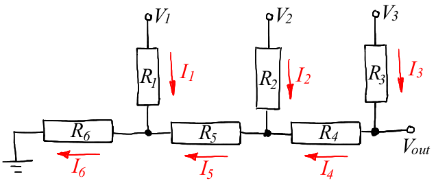
The theory tells us that if we choose R4 = R5 = R, and R1 = R2 = R3 = R6 = 2R, then, applying three bits of the binary number to the inputs V1, V2, V3, we get an analog level on the Vout node the entrance.
Reading the encyclopedia is good, but how were these denominations of R and 2R obtained? Let's find them yourself. So, the topology of the DAC is given to us, as before, arbitrarily choose the direction of current flow through each resistor.
The calculation method is exactly the same as in the previous example: first, we calculate the current for given resistors, and then we write several equations that connect Vout with inputs V1, V2 and V3, which will give us the necessary values.
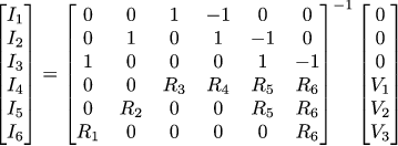
So, we have three nodes and three contours, as a result, six equations:

Rewrite in matrix form:

And then the strength of the currents can be found by reversing the 6x6 matrix:
Vout can be obtained as the sum of the voltage drops across three resistors:

For clarity, let me show you how Vout looks like a function of R1, R2, R3, R4, R5, R6 and V1, V2, V3:

Pretty unpleasant expression, right? Well, God be with him, we will not count hands. So, for given resistor ratings, we have seven non-zero combinations of input voltages at our DAC. They must match seven different Vout values. This will give seven equations, deciding which, we get the desired values of resistors.
As before, we will consider it in sage, here’s the code that can be run in the browser .
var("R1,R2,R3,R4,R5,R6,V1,V2,V3") A=matrix([[0,0,1,-1,0,0],[0,1,0,1,-1,0],[1,0,0,0,1,-1],[0,0,R3,R4,R5,R6],[0,R2,0,0,R5,R6],[R1,0,0,0,0,R6]]) b=matrix([[0],[0],[0],[V3],[V2],[V1]]) I=(A.inverse()*b).simplify_full() Vo=(I[5][0]*R6+I[4][0]*R5+I[3][0]*R4).simplify_full() eq7=(7/8==Vo.substitute(V1=1,V2=1,V3=1)) eq6=(6/8==Vo.substitute(V1=0,V2=1,V3=1)) eq5=(5/8==Vo.substitute(V1=1,V2=0,V3=1)) eq4=(4/8==Vo.substitute(V1=0,V2=0,V3=1)) eq3=(3/8==Vo.substitute(V1=1,V2=1,V3=0)) eq2=(2/8==Vo.substitute(V1=0,V2=1,V3=0)) eq1=(1/8==Vo.substitute(V1=1,V2=0,V3=0)) solve([eq1,eq2,eq3,eq4,eq5,eq6,eq7],R2,R3,R4,R5,R6) Here is the output of the solve command (I threw out all the solutions with negative and zero resistors) with my hands:
[R2 == r11, R3 == r12, R4 == -1/2*r11 + r12, R5 == -1/2*R1 + r11, R6 == R1]This means that we can select (almost) arbitrarily the resistors R1, R2, R3, and our DAC will work correctly. If we take them all three of the same denomination, then we get the well-known R-2R matrix.
Digital-to-analog conversion of the ternary code
And now we come to the most interesting, to the development of a digital-to-analog converter for a ternary balanced system. As far as I know, nobody has done this yet, few fools :)
In general, the resistor matrix works great for a binary code, but what happens if it sends a ternary signal to the input? If V1 = V2 = V3 = -1, then the output of the matrix will be approximately -1, if V1 = V2 = V3 = 0, then the output is zero, and if V1 = V2 = V3 = 1, then the output is approximately 1. Then there is, in the first approximation, the matrix works as we need. Let's try adjusting resistors to make it work quite well.
The topology of the matrix remains the same, the expression for Vout does not change, we only need to adjust the system of equations to search for nominal values. If earlier we had 7 equations, now it will be 13. Let's try!
var("R,R1,R2,R3,R4,R5,R6,V1,V2,V3") A=matrix([[0,0,1,-1,0,0],[0,1,0,1,-1,0],[1,0,0,0,1,-1],[0,0,R3,R4,R5,R6],[0,R2,0,0,R5,R6],[R1,0,0,0,0,R6]]) b=matrix([[0],[0],[0],[V3],[V2],[V1]]) I=(A.inverse()*b).simplify_full() Vo=(I[5][0]*R6+I[4][0]*R5+I[3][0]*R4).simplify_full() Vo=Vo.substitute(R1==R,R2==R,R3==R) eq13=(26/27==Vo.substitute(V1= 1,V2= 1,V3= 1)) eq12=(24/27==Vo.substitute(V1= 0,V2= 1,V3= 1)) eq11=(22/27==Vo.substitute(V1=-1,V2= 1,V3= 1)) eq10=(20/27==Vo.substitute(V1= 1,V2= 0,V3= 1)) eq09=(18/27==Vo.substitute(V1= 0,V2= 0,V3= 1)) eq08=(16/27==Vo.substitute(V1=-1,V2= 0,V3= 1)) eq07=(14/27==Vo.substitute(V1= 1,V2=-1,V3= 1)) eq06=(12/27==Vo.substitute(V1= 0,V2=-1,V3= 1)) eq05=(10/27==Vo.substitute(V1=-1,V2=-1,V3= 1)) eq04=( 8/27==Vo.substitute(V1= 1,V2= 1,V3= 0)) eq03=( 6/27==Vo.substitute(V1= 0,V2= 1,V3= 0)) eq02=( 4/27==Vo.substitute(V1=-1,V2= 1,V3= 0)) eq01=( 2/27==Vo.substitute(V1= 1,V2= 0,V3= 0)) sln=solve([eq01,eq02,eq03,eq04,eq05,eq06,eq07,eq08,eq09,eq10,eq11,eq12,eq13],R4,R5,R6) show(sln) As usual, this code can be run in a browser.
Well listen, and the system has a solution, if we take R1 = R2 = R3 = R, R4 = R5 = 4 / 3R and R6 = 2R, then we will have a real three-way DAC!
Theory by theory but let's test in practice
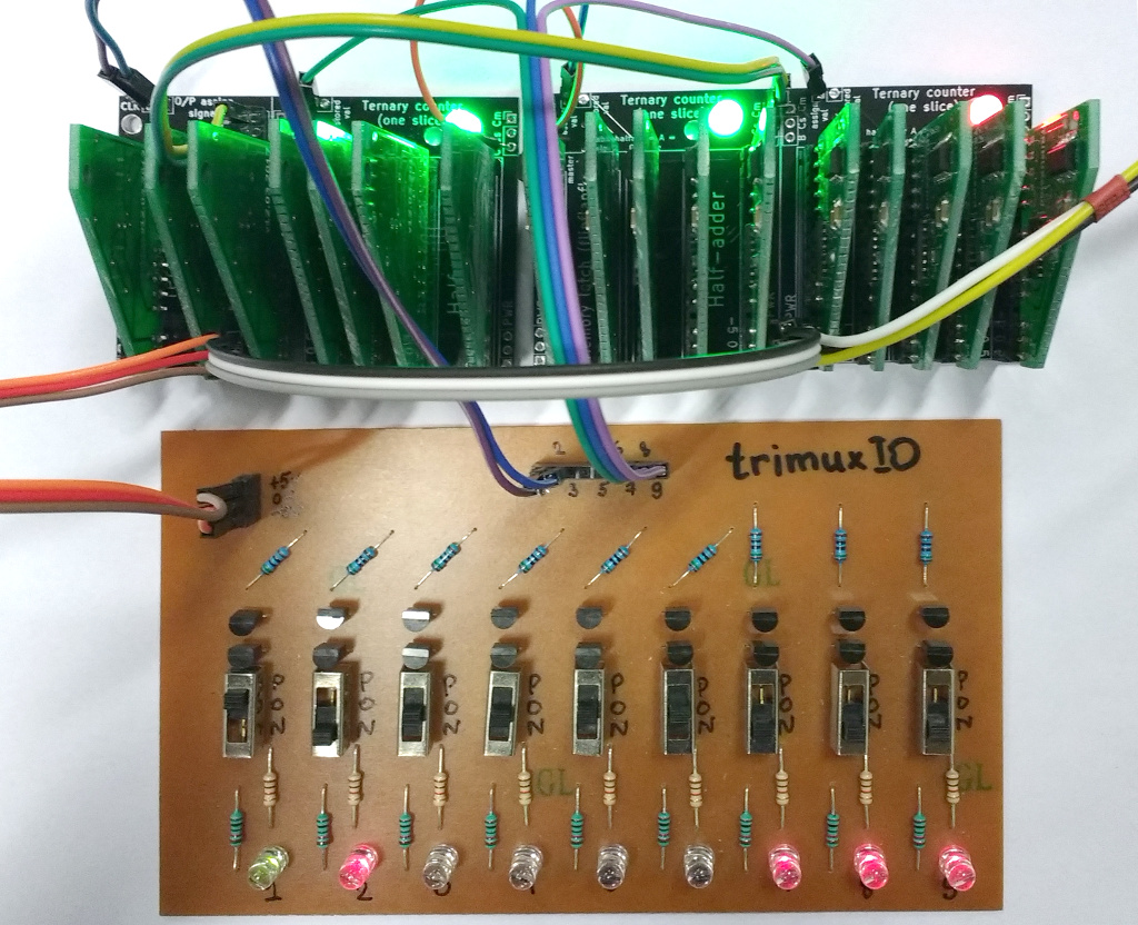
In order to check the operation of the DAC, we take the same most ternary counter that I described a little earlier. Clock counter will be triangular saw, the scheme is available here. And we will drive three digits of our meter to the three inputs of the ternary DAC. Here is the test pattern:

On the breadboard top are clock triangles, then a counter, on the breadboard bottom is a resistor matrix. In this matrix there are three resistors, I chose 1 kΩ, 1.33 kΩ and 2 kΩ. A three-digit counter counts from -13 to +13, at the output I expect to see a ladder from (approximately) -5 V to (approximately) +5 V. I poke with an oscilloscope:

It is clearly seen that each clock triangle generates another step for us. Works!
Bonus: how much can you trust math software?
Today we cheerfully considered crocodiles all sorts of software good. In general, how much can you trust what we have counted? I consider everyone to work a lot, find bugs in almost all mathematical packages. Here, for example, since we are talking about sage, a screenshot I took two and a half years ago when I sent a bugreport:

Who is right, the numerical integral of the function f or its symbolic calculation? They even have a different sign! Now the yard is the end of 2017, you can check the current state of things . Versions are replaced, and the error is still in place. Therefore , of course, it is possible to use mathematical software, but it is necessary to check the results in the same way as after outputting formulas on paper .
Source: https://habr.com/ru/post/341328/
All Articles