Connecting a remote COM controller to a computer’s USB port via unmatched lines
Until now, there are many devices that connect to a computer through the COM port, but since modern computers are less and less equipped with COM ports, communication with the COM devices is performed via USB ports supplemented with special signal converters. A significant increase in the frequency of signals in the USB lines (in comparison with the signals of the COM port) imposes a limit on the length of the lines, increases their cost and requires solving the problems of matching the lines. In this paper, using the example of an Arduino UNO controller, we consider connecting a COM device to a computer through long unmatched lines.
A typical scheme for connecting an Arduino UNO controller to a computer via a USB port is shown in Figure 1. On the computer side, the communication channel is visible as a standard COM port. But, in fact, this is a virtual COM port with which a computer exchanges data packets at a frequency of 12 MHz, and a specialized controller located on the Arduino UNO board converts USB data packets into a sequence of bits in the 0 / 5V asynchronous interface format. and are used by the main Arduino UNO controller (ATmega328P chip) for downloading programs and exchanging data with a computer during program execution.
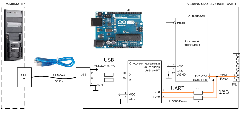
Figure 1. A typical connection of the Arduino UNO controller to a computer via USB port.
The timing diagram of serial data transmission according to the UART device rules with a signal level of 0 / 5V is shown in Figure 2. Data is transmitted by bytes. In addition to data, the sequence contains start and stop bits and may include other service bits, for example, the parity bit, the use of which is set in the COM port settings, one of the standard transmission rates is also set there.
')
Note. In the family of the asynchronous interface UART, the most commonly known standard is the RS-232 physical layer used by the computer's COM port.
The COM port does not have synchronization signals, time intervals are formed by both the transmitter and the receiver with a clocking accuracy of no worse than 5%.
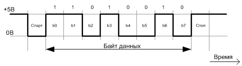
Figure 2. Timing diagram of UART serial data transfer (01001011) of the ATmega328P chip of the Arduino UNO controller.
The Arduino UNO controller contains a dedicated controller for converting UART signals to a USB sequence and vice versa. The computer's USB port communicating with the virtual COM port operates in Full-speed mode at a frequency of 12 Mbps (Figure 3). This mode supports both USB 1.0. and USB 2.0.
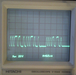
Figure 3. The measured 4B signal on the differential line USB – COM controller Arduino. USB cable length 2m. The frequency of the signals on the USB line is 12 MHz. For the formation of signals used to write data to the COM port of the controller. The frequency of 12 MHz USB data did not change when writing to the COM port at both 9600 bps and 115200 bps.
Data on the USB bus is transmitted in packets (Figure 4). The packet size depends on the type of transfer being performed. Each packet in Full-speed mode contains 8 clock bits for the receiver and transmitter (Sync), 8 bits for the packet identifier (PID), and 2 bits for the end of the packet (EOP). The data block can be from 0 to 1023 bytes.
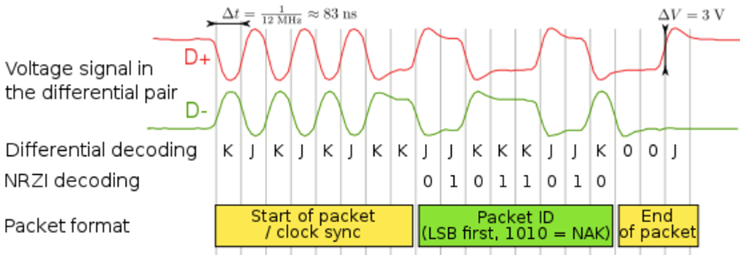
Figure 4. An example of transferring a packet over a USB 1.1 differential line in Full-speed mode [2]. The change in the state of the differential signal corresponds to the transfer of zero, the preservation of levels corresponds to the transfer of one. To improve synchronization on single sequences, forcibly insert zero for every 6 units in a row.
In addition to the data packet, other packets are transmitted. For all USB transfers, 2 or 3 packets of information are required to be transferred between the host controller and the receiver. If the transmission was successful, the destination returns an acknowledgment packet. If an error is detected during transmission, a no-notification packet is generated.
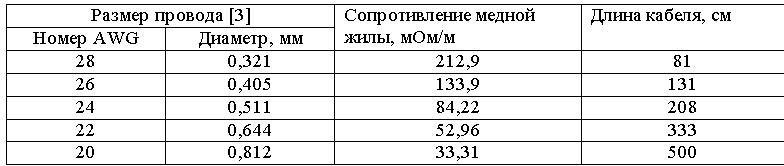
Differential USB signals are transmitted over a twisted pair shielded 4-wire cable. According to the standard, the cross section of the signal wires of the high speed USB 2.0 cable should be 28 AWG and from 20 to 28 AWG for the power supply wires, depending on the cable length (see Table 1).
Table 1. Approximate correspondence of the length and diameter of the wires of the USB2 cable.
Wire Size [3]
To increase the length of the USB cable, it is equipped with built-in signal amplifiers.
At the request of the USB 2.0 specification for High-speed mode (up to 480 Mbps), the signal propagation delay in the cable should not exceed 5.2 ns / m and be no more than 26 ns, which determines the maximum cable length of 5 m.
The delay per meter length in a coaxial cable is inversely proportional to the wave propagation velocity in m / s, which is calculated as
 ,
,
where c is the speed of light 3 * 10 ^ 8 m / s; e is the dielectric constant of the material of the inner insulator; u is the permeability of the insulator. For polyethylene with u = 1 and e = 2.2, the phase velocity is 2 * 10 ^ 8 m / s and, accordingly, the delay is 5 ns / m.
To reduce signal loss, it is important to ensure the uniformity of the wave resistance (s) of the signal line. Change v.s. may be due to poor cable sealing, poor matching of line elements, poor connector quality, etc.
The characteristic impedance of the cable is determined by its design. Vs coaxial cable in the high-frequency (30 kHz and above) is calculated by the following formula.
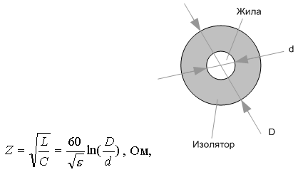
where L is the longitudinal inductance of the shorted cable, Gn; C is the transverse capacity of an open cable, F; e is the dielectric constant of the insulator; D is the diameter of the insulator; d is the conductor diameter. Value v.s. does not depend on cable length.
The dielectric constant of insulators lies in the range of 1 ... 7: 1 - air, vacuum; 1.3 ... 2.4 - polyethylene; 2.5..6 - rubber; 5..7 - porcelain; 6..7 - mica; 7 - glass.
Value v.s. The twisted pair USB 2.0 cable is 90 ± 15% ohms [5]. Calculation v.s. shielded twisted pair must take into account the relative position of the conductors.
In a matched cable whose load at the ends has a resistance equal to c., All transmitted electromagnetic energy is completely absorbed by the receiver without reflection. In non-uniform lines and with unmatched loads, reflected waves occur in places of electrical inconsistency and some energy returns to the beginning of the line.
The reflection coefficient of the waves in the cable is equal to
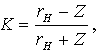 ,
,
where rH is the load resistance; Z - w.s. cable.
Incorporating unmatched elements into a USB line can significantly distort the signal. For example, the line turns out to be inoperable when electric wires from a power cable with a wave resistance of 10 ... 40 Ω are inserted into it.
To ensure stable communication of a remote COM device with a computer through a USB port, the length of the USB channel is minimized, a USB - RS-232 converter is supplied at the USB output, which is connected to a level converter + 15 / -15V == 0 / 5V through a long line, located near the Arduino controller and connected to its UART port, as shown in Figure 5. The data exchange rate in this structure is the same as when the Arduino is connected to a computer via a USB cable, but the signal frequency in a long line is almost 100 times lower - as 0 , 115200 Mbit / s and 12 Mbit / s.

Figure 5. Connection diagram of the Arduino UNO controller to the computer via the USB port and long unmatched lines. The designation of the GND pins, the Tx transmitter, and the Rx receiver on the standard DB-9 connector on the computer's COM port is shown at the top left. On the device side, the TxD and RxD signals on the DB-9 connector must be swapped.
The RS232 level converter (Figure 5) does not change the sequence of bits. It changes the signal levels of 0/5 V to + 12 / -12 V and vice versa (Figure 6).
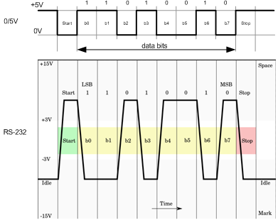
Figure 6. Timing diagram and signal levels of an RS232 converter.
For the conversion of RS232 signal levels, microcircuits can be used, for example, MAX232 (from Maxim Integrated Products), SP232 (Sipex), ADM232 (Analog Devices). These chips have the same characteristics and pin assignments. The connection of the MAX232 converter is shown in Figure 7 [6].
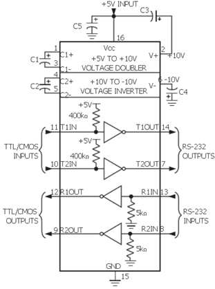
Figure 7. Wiring diagram for level converter MAX232. The circuit provides an output voltage level of approximately ± 7.5 V corresponding to the RS-232 interface.
The market offers many modules of level converters built on the base of the listed and other microcircuits. The appearance of one of these modules is shown in (Figure 5).
The device can be connected to a computer via a standard COM port, if it exists, or use a USB-RS232 converter (also called USB-COM converters, adapters or adapters) connected directly to the USB port or via its own USB cable. The appearance of USB converters is shown in Figure 5.
An implementation option for the COM device line layout is a USB port of a computer without an RS-232 line shown in Figure 8.
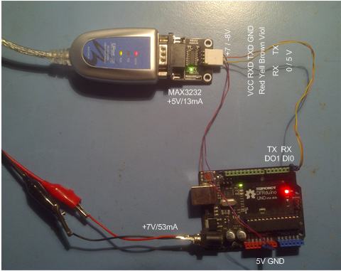
Figure 8. A variant of connecting an Arduino UNO controller to a computer's USB-COM converter.
To test the performance of the data exchange channel between the Arduino UNO controller and the computer, the wire shown in Figure 9 and Figure 10 was assembled through a long unmatched line. The wire pieces were twisted together or held in the socket slots for friction.
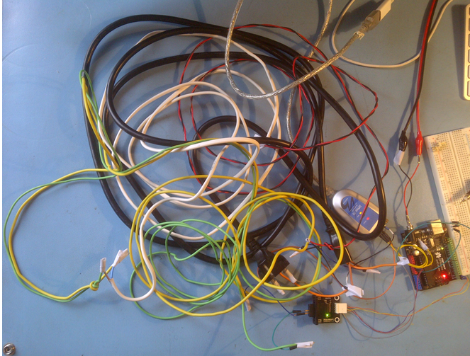
Figure 9. RS232 channel of 9.5 m composite cable
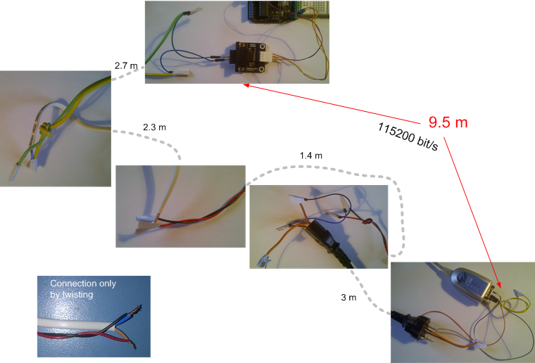
Figure 10. Pieces of RS232 wire from a 9.5 m composite cable.
Transmission and reception of data through the COM port of the Arduino UNO controller was controlled by the COM Port Toolkit computer utility.
The Arduino UNO program used for testing the line, transmitting data bytes to the COM and switching the controller LED on the arrival of external commands is shown below.
Waveforms of signals taken at the ends of the RS-232 line consisting of pieces are shown in Figure 11. Data is transmitted at a frequency of 115200 bps.
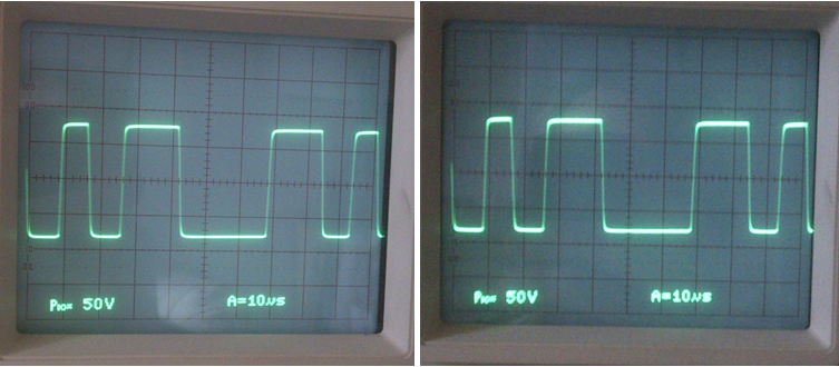
Figure 11. Signal amplitude + 7.5 / -8 V at the ends of the RS-232 line of a composite cable with a length of 9.5 m. The data transmission frequency is 115200 bps. The signal has no noticeable distortion.
Programs are loaded into the Arduino controller using its internal loader, which starts immediately after turning on the controller's power supply, or after pressing the reset button on the board, or when the computer sends a reset signal through the USB line.
When the Arduino board was connected via an RS-232 channel with two Tx and Rx signal lines with no reset signal line, the download was performed in the following order.
1. The Arduino development environment was launched (as well as in the download mode via USB).
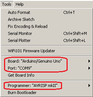
2. The program was loaded (as in the download mode via USB).
3. The firmware of the program was launched with the command Ctrl + U or via the button (as in boot mode via USB)
4. Additionally, after starting the firmware and filling the progress indicator Reset button was pressed
  on the Arduino controller board for approximately 0.5 seconds.
Successful firmware ends with a message.
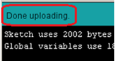 .
.
The firmware was executed successfully even with a brief power-off of the controller, instead of pressing the Reset button.
The launch of the Arduino controller loader can be performed automatically from the computer, without pressing the Reset button or momentary power failure. For this, it is necessary, for example, to complement the RS-232 channel with Tx, Rx, and GND with an RTS line and connect it via the level converter to the RESET input of the Arduino controller.
1. WikipediA. The Free Encyclopedia.
2. WikipediA. The Free Encyclopedia.
3. WikipediA. The Free Encyclopedia.
4. Ways to transmit over twisted pairs.
5. USB2.0 A plug B plug multimedia cable.
6. + 5V-Powered, Multichannel RS-232 Drivers / Receivers.
7. Dr. Bob Davidov. Serial data port interface converter.
8. Dr. Bob Davidov.
USB channel structure - Arduino UNO board
A typical scheme for connecting an Arduino UNO controller to a computer via a USB port is shown in Figure 1. On the computer side, the communication channel is visible as a standard COM port. But, in fact, this is a virtual COM port with which a computer exchanges data packets at a frequency of 12 MHz, and a specialized controller located on the Arduino UNO board converts USB data packets into a sequence of bits in the 0 / 5V asynchronous interface format. and are used by the main Arduino UNO controller (ATmega328P chip) for downloading programs and exchanging data with a computer during program execution.
Figure 1. A typical connection of the Arduino UNO controller to a computer via USB port.
The timing diagram of serial data transmission according to the UART device rules with a signal level of 0 / 5V is shown in Figure 2. Data is transmitted by bytes. In addition to data, the sequence contains start and stop bits and may include other service bits, for example, the parity bit, the use of which is set in the COM port settings, one of the standard transmission rates is also set there.
')
Note. In the family of the asynchronous interface UART, the most commonly known standard is the RS-232 physical layer used by the computer's COM port.
The COM port does not have synchronization signals, time intervals are formed by both the transmitter and the receiver with a clocking accuracy of no worse than 5%.
Figure 2. Timing diagram of UART serial data transfer (01001011) of the ATmega328P chip of the Arduino UNO controller.
The Arduino UNO controller contains a dedicated controller for converting UART signals to a USB sequence and vice versa. The computer's USB port communicating with the virtual COM port operates in Full-speed mode at a frequency of 12 Mbps (Figure 3). This mode supports both USB 1.0. and USB 2.0.
Figure 3. The measured 4B signal on the differential line USB – COM controller Arduino. USB cable length 2m. The frequency of the signals on the USB line is 12 MHz. For the formation of signals used to write data to the COM port of the controller. The frequency of 12 MHz USB data did not change when writing to the COM port at both 9600 bps and 115200 bps.
Data on the USB bus is transmitted in packets (Figure 4). The packet size depends on the type of transfer being performed. Each packet in Full-speed mode contains 8 clock bits for the receiver and transmitter (Sync), 8 bits for the packet identifier (PID), and 2 bits for the end of the packet (EOP). The data block can be from 0 to 1023 bytes.
Figure 4. An example of transferring a packet over a USB 1.1 differential line in Full-speed mode [2]. The change in the state of the differential signal corresponds to the transfer of zero, the preservation of levels corresponds to the transfer of one. To improve synchronization on single sequences, forcibly insert zero for every 6 units in a row.
In addition to the data packet, other packets are transmitted. For all USB transfers, 2 or 3 packets of information are required to be transferred between the host controller and the receiver. If the transmission was successful, the destination returns an acknowledgment packet. If an error is detected during transmission, a no-notification packet is generated.
Differential USB signals are transmitted over a twisted pair shielded 4-wire cable. According to the standard, the cross section of the signal wires of the high speed USB 2.0 cable should be 28 AWG and from 20 to 28 AWG for the power supply wires, depending on the cable length (see Table 1).
Table 1. Approximate correspondence of the length and diameter of the wires of the USB2 cable.
Wire Size [3]
To increase the length of the USB cable, it is equipped with built-in signal amplifiers.
At the request of the USB 2.0 specification for High-speed mode (up to 480 Mbps), the signal propagation delay in the cable should not exceed 5.2 ns / m and be no more than 26 ns, which determines the maximum cable length of 5 m.
The delay per meter length in a coaxial cable is inversely proportional to the wave propagation velocity in m / s, which is calculated as
,where c is the speed of light 3 * 10 ^ 8 m / s; e is the dielectric constant of the material of the inner insulator; u is the permeability of the insulator. For polyethylene with u = 1 and e = 2.2, the phase velocity is 2 * 10 ^ 8 m / s and, accordingly, the delay is 5 ns / m.
To reduce signal loss, it is important to ensure the uniformity of the wave resistance (s) of the signal line. Change v.s. may be due to poor cable sealing, poor matching of line elements, poor connector quality, etc.
The characteristic impedance of the cable is determined by its design. Vs coaxial cable in the high-frequency (30 kHz and above) is calculated by the following formula.
where L is the longitudinal inductance of the shorted cable, Gn; C is the transverse capacity of an open cable, F; e is the dielectric constant of the insulator; D is the diameter of the insulator; d is the conductor diameter. Value v.s. does not depend on cable length.
The dielectric constant of insulators lies in the range of 1 ... 7: 1 - air, vacuum; 1.3 ... 2.4 - polyethylene; 2.5..6 - rubber; 5..7 - porcelain; 6..7 - mica; 7 - glass.
Value v.s. The twisted pair USB 2.0 cable is 90 ± 15% ohms [5]. Calculation v.s. shielded twisted pair must take into account the relative position of the conductors.
In a matched cable whose load at the ends has a resistance equal to c., All transmitted electromagnetic energy is completely absorbed by the receiver without reflection. In non-uniform lines and with unmatched loads, reflected waves occur in places of electrical inconsistency and some energy returns to the beginning of the line.
The reflection coefficient of the waves in the cable is equal to
,where rH is the load resistance; Z - w.s. cable.
Incorporating unmatched elements into a USB line can significantly distort the signal. For example, the line turns out to be inoperable when electric wires from a power cable with a wave resistance of 10 ... 40 Ω are inserted into it.
USB channel structure - RS-232 - Arduino UNO board
To ensure stable communication of a remote COM device with a computer through a USB port, the length of the USB channel is minimized, a USB - RS-232 converter is supplied at the USB output, which is connected to a level converter + 15 / -15V == 0 / 5V through a long line, located near the Arduino controller and connected to its UART port, as shown in Figure 5. The data exchange rate in this structure is the same as when the Arduino is connected to a computer via a USB cable, but the signal frequency in a long line is almost 100 times lower - as 0 , 115200 Mbit / s and 12 Mbit / s.
Figure 5. Connection diagram of the Arduino UNO controller to the computer via the USB port and long unmatched lines. The designation of the GND pins, the Tx transmitter, and the Rx receiver on the standard DB-9 connector on the computer's COM port is shown at the top left. On the device side, the TxD and RxD signals on the DB-9 connector must be swapped.
The RS-232 interface has the following characteristics [7,8].
Signal transmission method Single phase
Maximum number of receivers 1
Maximum baud rate of 460 kbps
Maximum cable length 15 m (for 460 kbps)
Common-mode voltage at the output ± 25V
Impedance load 3 ..7 kOhm
Allowable signal range at the receiver input ± 25V
± 3V receiver sensitivity
Input impedance of the receiver 3 ..7 kOhm
Load capacity not more than 2500 pcf *
______________________
* When using a cable with a small capacity of communication can be maintained at distances up to 300 m [1].
The RS232 level converter (Figure 5) does not change the sequence of bits. It changes the signal levels of 0/5 V to + 12 / -12 V and vice versa (Figure 6).
Figure 6. Timing diagram and signal levels of an RS232 converter.
For the conversion of RS232 signal levels, microcircuits can be used, for example, MAX232 (from Maxim Integrated Products), SP232 (Sipex), ADM232 (Analog Devices). These chips have the same characteristics and pin assignments. The connection of the MAX232 converter is shown in Figure 7 [6].
Figure 7. Wiring diagram for level converter MAX232. The circuit provides an output voltage level of approximately ± 7.5 V corresponding to the RS-232 interface.
The market offers many modules of level converters built on the base of the listed and other microcircuits. The appearance of one of these modules is shown in (Figure 5).
The device can be connected to a computer via a standard COM port, if it exists, or use a USB-RS232 converter (also called USB-COM converters, adapters or adapters) connected directly to the USB port or via its own USB cable. The appearance of USB converters is shown in Figure 5.
An implementation option for the COM device line layout is a USB port of a computer without an RS-232 line shown in Figure 8.
Figure 8. A variant of connecting an Arduino UNO controller to a computer's USB-COM converter.
To test the performance of the data exchange channel between the Arduino UNO controller and the computer, the wire shown in Figure 9 and Figure 10 was assembled through a long unmatched line. The wire pieces were twisted together or held in the socket slots for friction.
Figure 9. RS232 channel of 9.5 m composite cable
Figure 10. Pieces of RS232 wire from a 9.5 m composite cable.
Transmission and reception of data through the COM port of the Arduino UNO controller was controlled by the COM Port Toolkit computer utility.
The Arduino UNO program used for testing the line, transmitting data bytes to the COM and switching the controller LED on the arrival of external commands is shown below.
void setup() { pinMode(LED_BUILTIN, OUTPUT); Serial.begin(115200); // , 9600,115200 } void loop() { if (Serial.available() >0) { mode = Serial.read(); // read byte switch (mode) { case 1: digitalWrite(LED_BUILTIN, HIGH); // turn the LED on break; case 2: digitalWrite(LED_BUILTIN, LOW); // turn the LED off break; } } Serial.print(5); // 6 or 9 } Waveforms of signals taken at the ends of the RS-232 line consisting of pieces are shown in Figure 11. Data is transmitted at a frequency of 115200 bps.
Figure 11. Signal amplitude + 7.5 / -8 V at the ends of the RS-232 line of a composite cable with a length of 9.5 m. The data transmission frequency is 115200 bps. The signal has no noticeable distortion.
Arduino UNO controller firmware
Programs are loaded into the Arduino controller using its internal loader, which starts immediately after turning on the controller's power supply, or after pressing the reset button on the board, or when the computer sends a reset signal through the USB line.
When the Arduino board was connected via an RS-232 channel with two Tx and Rx signal lines with no reset signal line, the download was performed in the following order.
1. The Arduino development environment was launched (as well as in the download mode via USB).
2. The program was loaded (as in the download mode via USB).
3. The firmware of the program was launched with the command Ctrl + U or via the button
(as in boot mode via USB)4. Additionally, after starting the firmware and filling the progress indicator
Reset button was pressed on the Arduino controller board for approximately 0.5 seconds.Successful firmware ends with a message.
.The firmware was executed successfully even with a brief power-off of the controller, instead of pressing the Reset button.
The launch of the Arduino controller loader can be performed automatically from the computer, without pressing the Reset button or momentary power failure. For this, it is necessary, for example, to complement the RS-232 channel with Tx, Rx, and GND with an RTS line and connect it via the level converter to the RESET input of the Arduino controller.
Conclusion
- The transfer of COM data through an extended USB line is carried out by packets at higher frequencies (12 MHz) and requires a matched line.
- Minimizing the length of the USB path and the use of a long line to transfer COM data directly made it possible to ensure reliable data transmission through pieces of inconsistent wires with a total length of 9.5 m.
- RS-232 data transmission at low frequencies along lines with a small capacity (less than 2500 pF) can be carried out at distances up to 300 m.
- The use of RS-422 or 485 differential lines for remote communications with a computer’s USB port allows you to increase the distance up to 1200 m, but when solving the issue of matching the lines.
Literature
1. WikipediA. The Free Encyclopedia.
2. WikipediA. The Free Encyclopedia.
3. WikipediA. The Free Encyclopedia.
4. Ways to transmit over twisted pairs.
5. USB2.0 A plug B plug multimedia cable.
6. + 5V-Powered, Multichannel RS-232 Drivers / Receivers.
7. Dr. Bob Davidov. Serial data port interface converter.
8. Dr. Bob Davidov.
Source: https://habr.com/ru/post/341172/
All Articles