How to render frame Unreal Engine
Once I looked for the Unreal source code and, inspired by an excellent analysis of how popular games render a frame ( translation of an article on Habré), I decided to do something similar with it, too, to study how the engine renders the frame (with the parameters and settings of the scene on default).
Since we have access to the source code, we can examine the source of the renderer to understand what it does, however, this is quite a voluminous part of the engine, and the rendering paths are highly context-sensitive, so it will be easier to explore the pure low-level API (sometimes looking at the code, to fill in the blanks).
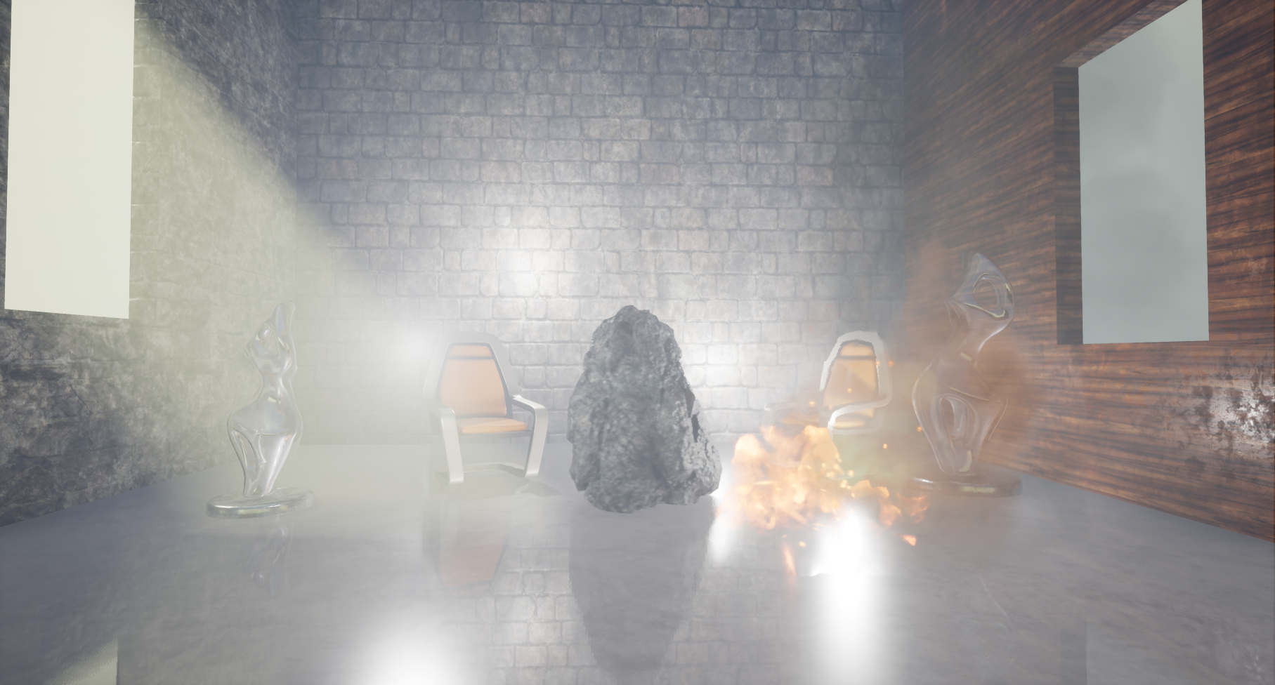
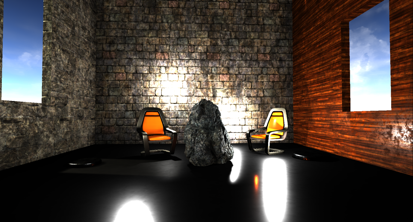
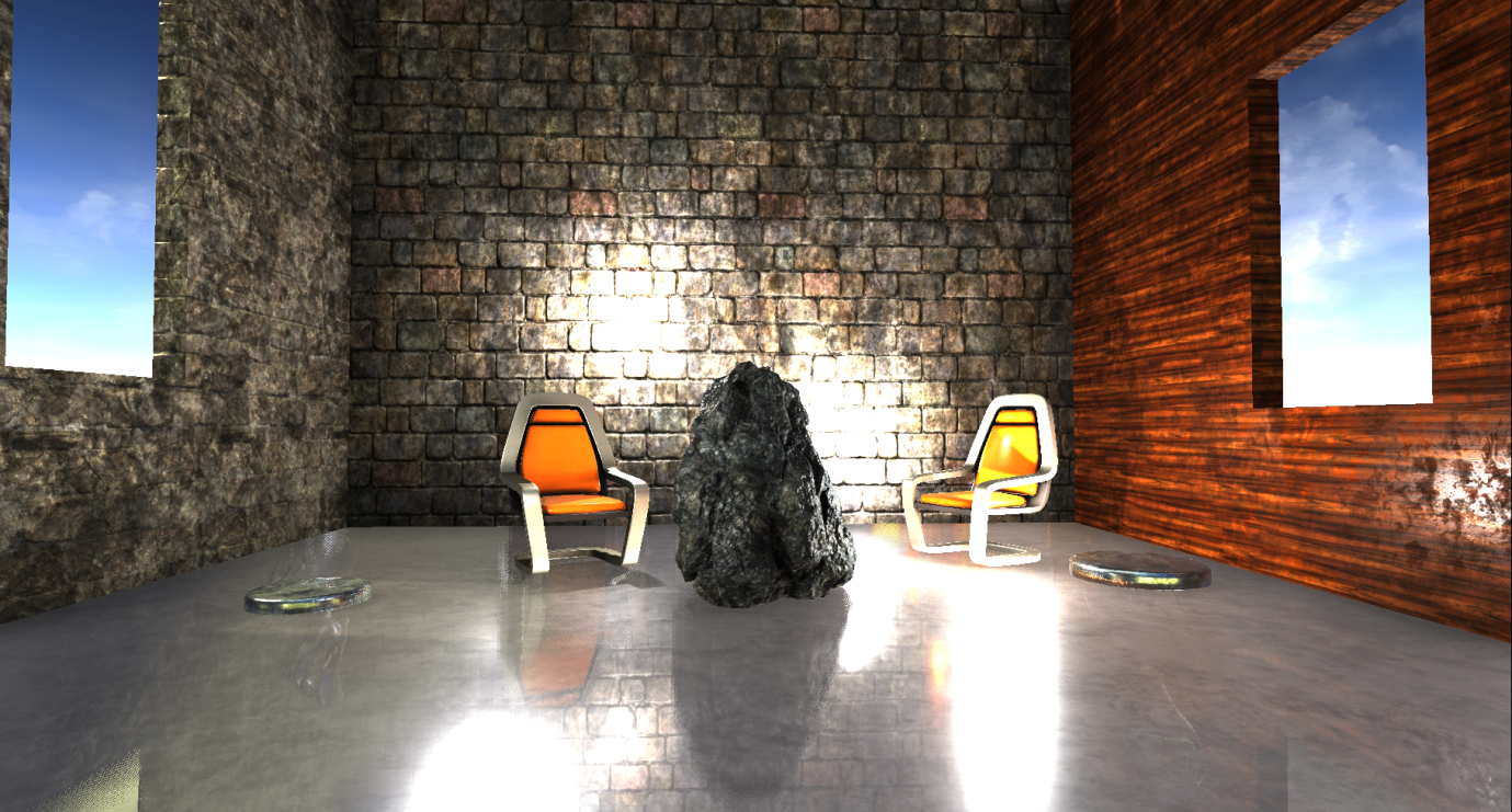
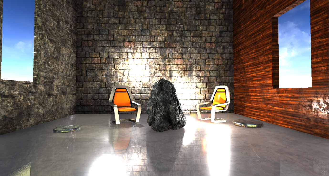
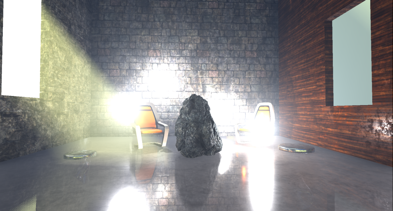
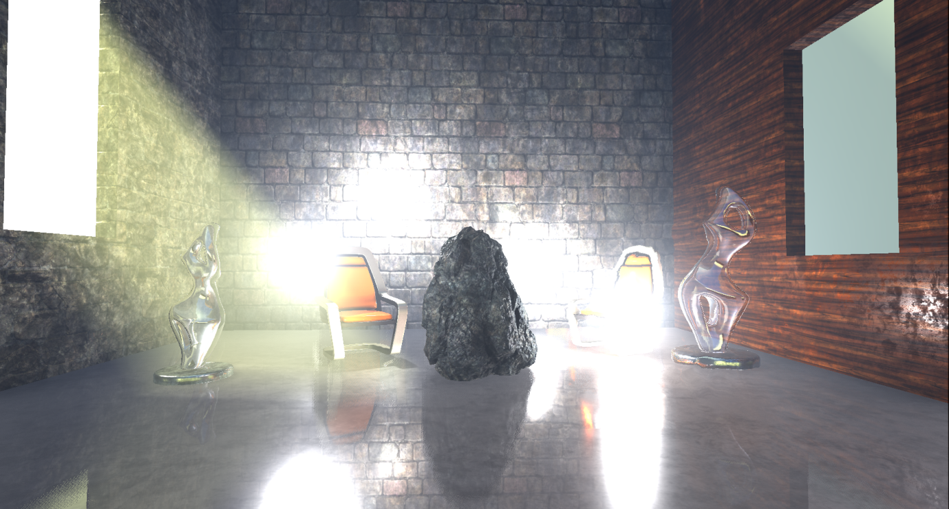
I assembled a simple scene with several static and dynamic props, several light sources, volume fog, transparent objects and particle effects to use a fairly wide range of materials and rendering methods.
')
So, I skipped Editor through RenderDoc and turned on capture. Perhaps this is not too similar to what a real game frame will look like, but it will give us a rough idea of how Unreal renders the standard frame (I did not change any settings and chose the maximum quality for the PC):
Note: the analysis is based on the capture of the video processor information and the source code of the renderer ( version 4.17.1 ). Before this project, I didn’t have much experience with Unreal. If I missed something or in something was mistaken, then let me know in the comments.
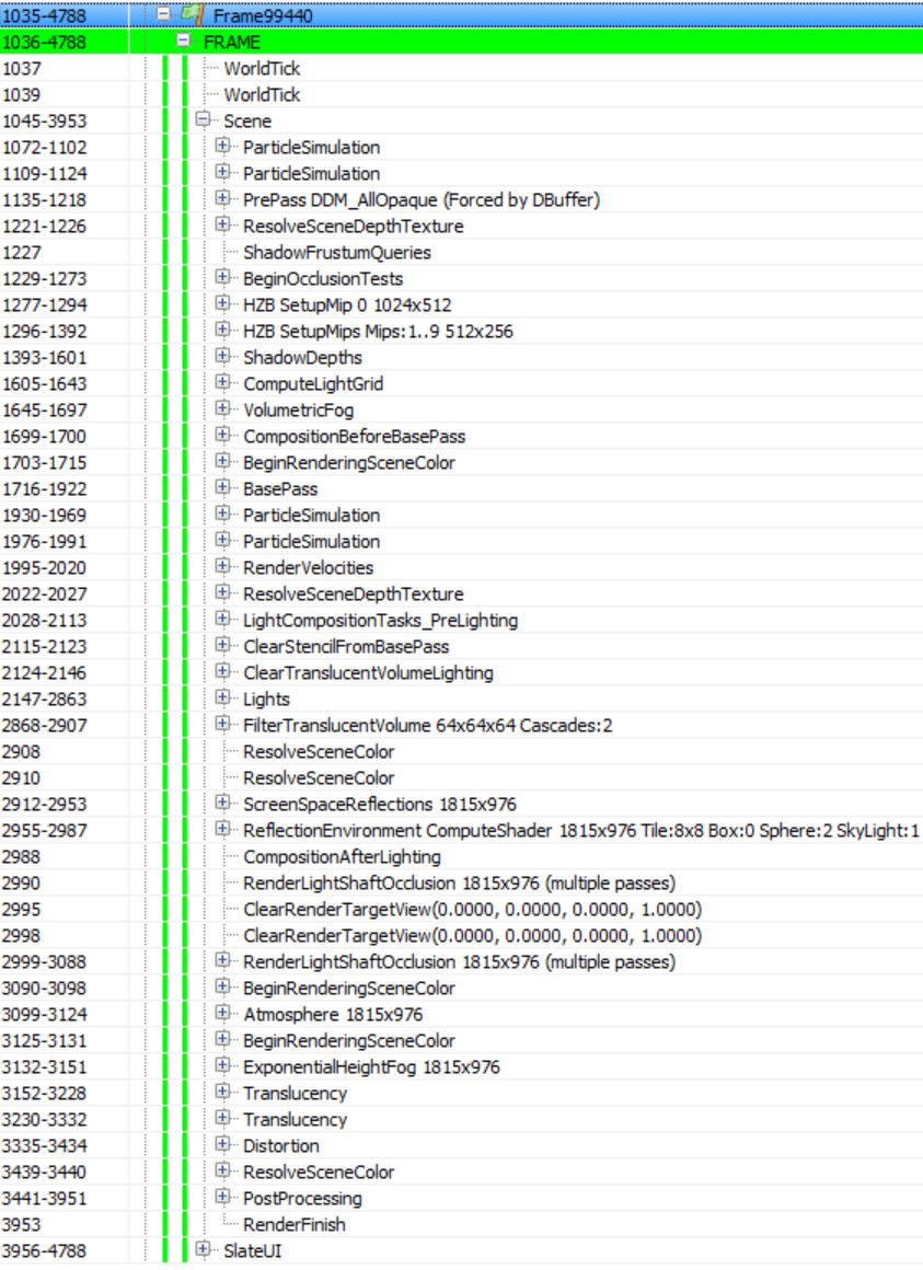
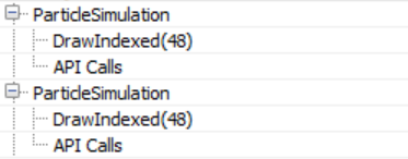
Fortunately, the Unreal drawing call list is clear and well annotated, and it will simplify our work. The list may look different if there are no entities / materials in the scene, or if a lower quality is chosen. For example, if you render without particles, there will be no ParticleSimulation passes.
The SlateUI rendering pass contains all API calls performed by the Unreal Editor to render its UI, so we will skip it and focus on all passes in the Scene section.
Particle simulation
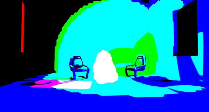
The frame begins with the passage of ParticleSimulation . It calculates the motion of particles in the video processor and other properties for each particle emitter in the scene for two target renders: RGBA32_Float (positions are written here) and RGBA16_Float (speeds) (and pairs of data / time / life). Here, for example, is the output for the target render RGBA32_Float, where each pixel corresponds to the position of the sprite in the world:
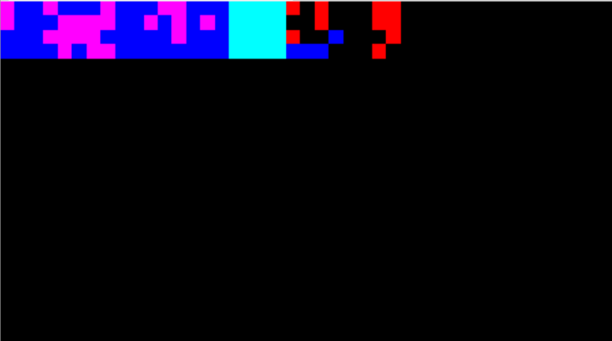
It seems that in this case the particle effect added by me to the scene has two emitters requiring simulation in the video processor without calculating collisions, so the corresponding rendering passes can be performed in the early stages of frame creation.
Z-Bump Pre-Pass
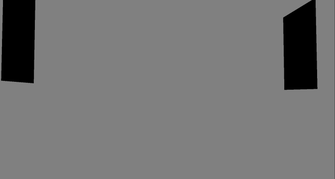
Next is the PrePass rendering pass , which is the preliminary pass of the z-buffer. It renders all opaque polygonal meshes (meshes) into the R24G8 depth buffer:
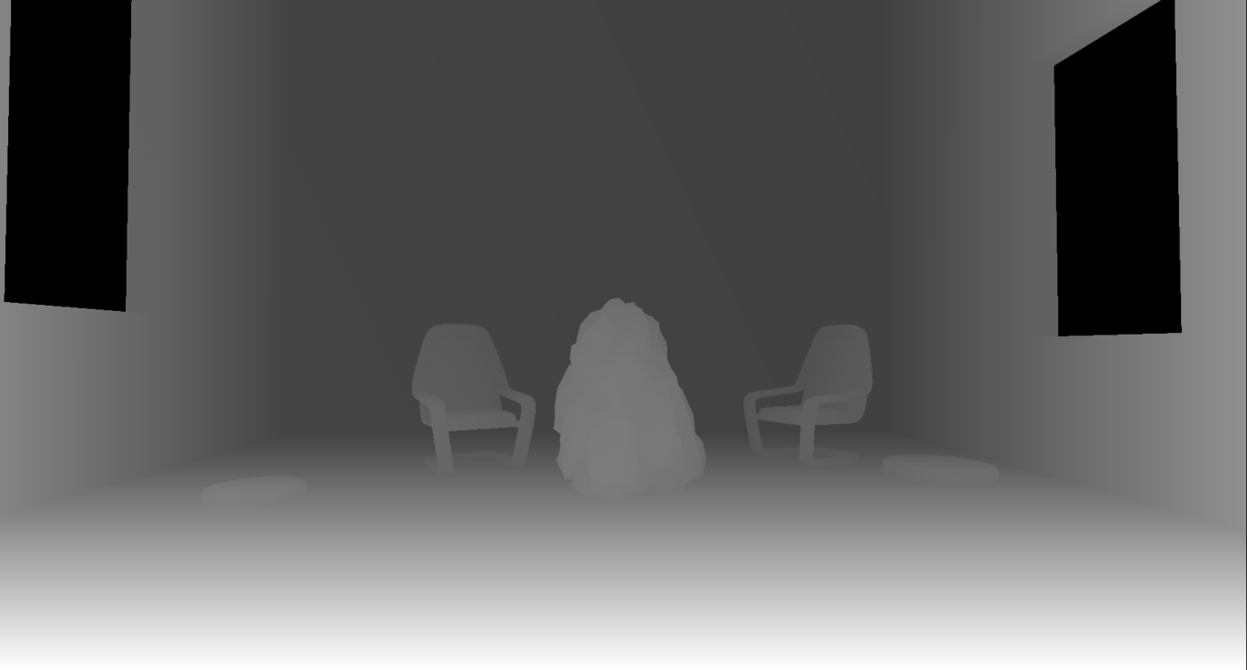
It is worth noting that in Unreal, when rendering into the depth buffer, a reverse Z-buffer (reverse-Z) is used . This means that the near plane is assigned the value 1, and the distant one - 0. This provides greater accuracy along the depth range and reduces the number of z-collisions for distant grids. The name of the rendering pass implies that the pass is triggered by the buffer “DBuffer”. This is the name of the decal buffer that the Unreal Engine uses to render deferred decals. It requires the depth of the scene, so the Z-buffer pre-pass is activated. But, as we will see below, the Z-buffer is used in other contexts, for example, for calculating overlaps (occlusion) and reflections in screen space.
Some render passes in the list are empty. for example, ResolveSceneDepth , which, I believe, is necessary for platforms that really require “resolving by depth” of the target render before using it as a texture (it is not needed on a PC), as well as ShadowFrustumQueries , which looks like a dummy marker, because the real overlap tests for shadows are performed in the next render pass.
Overlap check
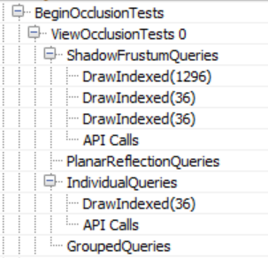
BeginOcclusionTests handles all overlap checks in a frame. By default, Unreal uses hardware occlusion queries to check for overlap. In short, it is performed in three stages:
- We render everything that we perceive as an overlapping object (for example, a large opaque mesh) to the depth buffer
- Create an overlap request, pass it and render the props for which we want to define the overlap. This is implemented using the z-test and the depth buffer created in step 1. The query returns the number of pixels that passed the z-test, that is, if the value is zero, then the entire props is located behind an opaque grid. Since rendering the entire grid of a props for overlapping can be costly, we use as a replacement the boundary box of this props. If it is invisible, then the props is also absolutely invisible.
- We read the results of the query back to the video processor and based on the number of rendered pixels we can choose whether to send the props for rendering or not (even if we see a small number of pixels, we can decide that the props should not be rendered).
Unreal uses different types of overlap requests, depending on the context:
Hardware overlap requests have their drawbacks - they have fragmentation of draw calls. This means that they require the renderer to perform a single draw call per grid (or group of grids) for which you need to define an overlap. They can significantly increase the number of draw calls per frame, require reading back to the CPU, which adds synchronization points between the CPU and the video processor, and cause the CPU to wait for the video processor to finish processing the request. They are not very suitable for the cloned geometry, but for now we will not pay attention to it.
Unreal solves the problem of the synchronization point of the CPU and the video processor like any other engine that uses queries — read the request data deferred for several frames. This approach works, but it can add the problem of “jumping out” props onto the screen when the camera moves rapidly (in practice this may not be a serious problem, because cutting off overlaps with the help of boundary boxes is conservative, that is, the grid is likely to be labeled as visible even before it actually becomes visible). However, there remains the problem of unnecessary draw calls, and it is not so easy to solve. Unreal tries to reduce its impact by grouping requests as follows: first, it renders all opaque geometry into a z-buffer (the Z-buffer described above is described above). It then transmits separate requests for each props to be checked for overlap. At the end of the frame, it receives the request data from the previous (or even earlier) frame and resolves the problem of visibility of the props. If it is visible, the engine marks it for rendering in the next frame. On the other hand, if it is invisible, the engine adds it to the “grouped” query, which combines the boundary parallelepipeds of the props (maximum eight objects) and uses it to determine visibility during the next frame. If in the next frame the group becomes visible (as a whole), the engine breaks it up and sends individual requests again. If the camera and props are static (or moving slowly), then this approach reduces the number of required floor requirements by a factor of eight. The only oddity that I noticed during the grouping (batching) of the overlapping props was that it seems random and does not depend on the spatial proximity of the props to each other.
This process corresponds to the IndividualQueries and GroupedQueries markers in the above list of render passes. The GroupedQueries part is empty because the engine was unable to create a query during the previous frame.
To complete the passage of overlaps, ShadowFrustumQueries transmits hardware requests for overlaps of boundary grids of local (point or directional) (casting and not casting a shadow, contrary to the name of the passage). If they are overlapped, then there is no point in calculating the lighting / shadows for them. It is worth noting that despite the presence in the scene of four local light sources casting a shadow (for which you need to compute a shadow map for each frame), the number of draw calls in ShadowFrustumQueries is three. I suspect this is so, because the limiting volume of one of the sources crosses the near plane of the camera, so Unreal believes that it will still be visible. It is also worth mentioning that for dynamic lighting, which calculates a cubic shadow map, we pass a sphere for the overlap checks,
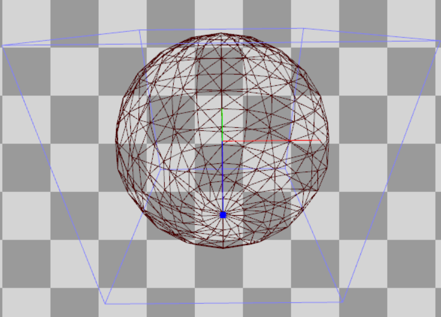
and for static dynamic lighting, which Unreal calculates for the shadows of each object (more on this below), the pyramid is transmitted:
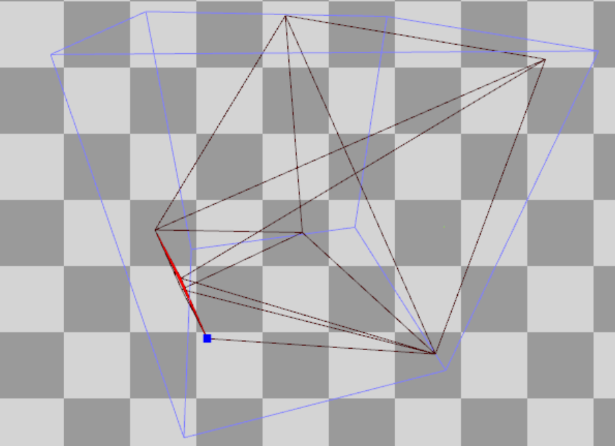
Finally, I assume that PlanarReflectionQueries refers to overlap tests performed when calculating plane reflections (created by moving the camera behind / in front of the plane of the reflections and redrawing the grids).
Hi-Z Buffer Generation
Unreal then creates a Hi-Z buffer ( HZB SetupMipXX passes ) stored as a 16-bit floating point number (texture format R16_Float). It receives as input the depth buffer created during the preliminary passage of the Z-buffer and creates a mip-chain (i.e., gradually reduces their resolution) depths. It also seems that for convenience, he resampls the first mip to the size of a power of two:


Since, as mentioned above, Unreal uses a reverse Z-buffer, the pixel shader uses the min operator to reduce the expansion.
Rendering shadow maps
This is followed by a rendering of the computation of the shadow map ( ShadowDepths ).
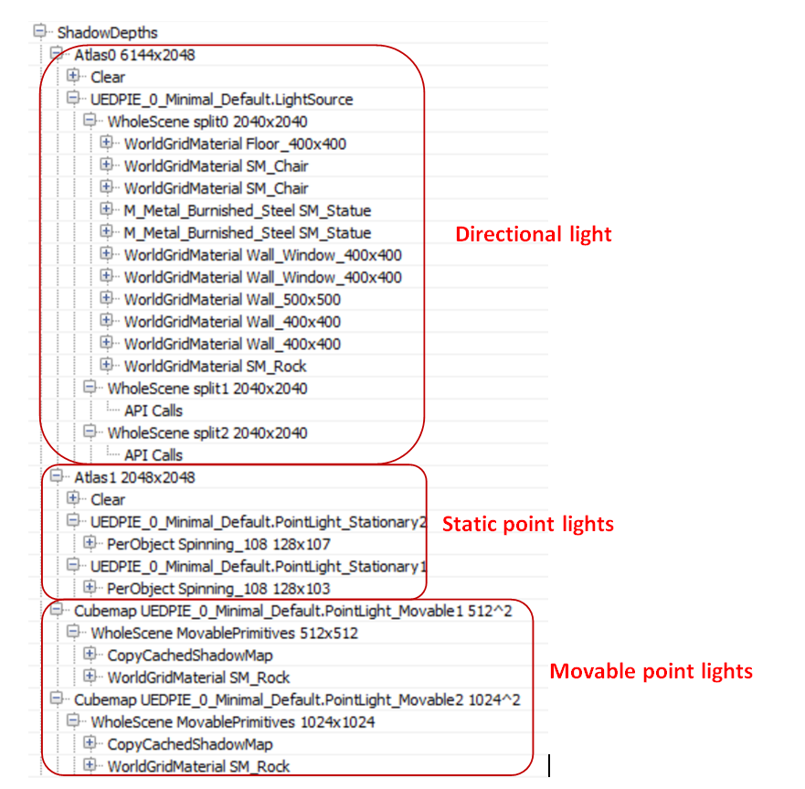
I added a “stationary” (Stationary) directional light source, two “Movable” point sources, two stationary point sources, and a “static” (Static) point source to the scene. They all cast shadows:

In the case of stationary sources, the renderer bakes the shadows of static props and calculates the shadows only for dynamic (mobile) props. In the case of mobile sources, it calculates the shadows for everything and every frame (fully dynamic). Finally, in the case of static sources, it bakes the lighting + shadows into the lighting map so that they never appear during rendering.
For the directional light source, I also added a cascading shadow map with three divisions to see how Unreal handles them. Unreal creates a shadow map texture R16_TYPELESS (three tiles in a row, one for each division), which is reset in each frame (therefore, there are no torn updates to the shadow map partitions based on the distance in the engine). Then, at the Atlas0 pass stage, the engine renders all the opaque props into the corresponding shadow map file:

As the above call list confirms, only in Split0 there is a geometry for rendering, so the other tiles are empty. The shadow map is rendered without using a pixel shader, which doubles the speed at which the shadow map is generated. It is worth noting: it seems that the separation between Stationary and Movable is not saved for a directional (source) light source, the renderer renders all props (including static ones) into the shadow map.
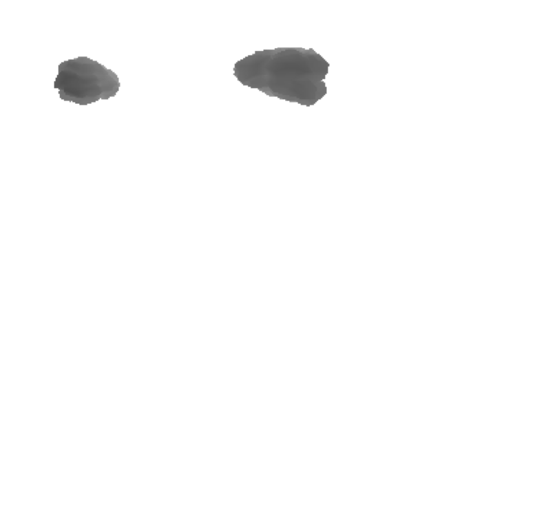
Next is the Atlas1 pass, which renders shadow maps for all stationary light sources. In my scene is marked as moving (dynamic) only prop "stone". For stationary sources and dynamic props, Unreal uses object-specific shadow maps stored in a texture atlas. This means that it renders for each source and for dynamic props one shadow map tile:
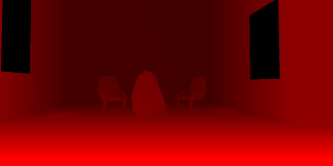
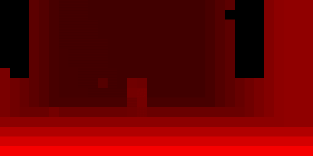
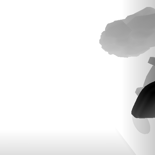
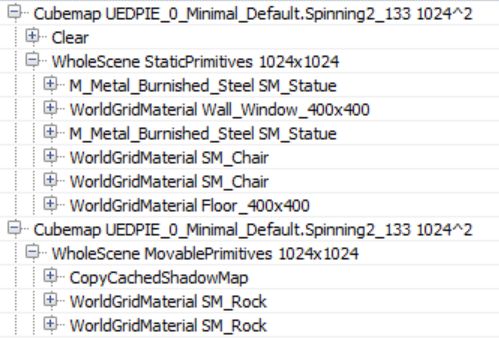
Finally, for each dynamic (moving) light source, Unreal creates a traditional cube shadow map ( Cubemap XX passes), using a geometry shader to select the face of the cube on which to render (to reduce the number of draw calls). In it, it only renders dynamic props using caching of shadow maps for static / stationary props. The CopyCachedShadowMap pass copies the cached cube shadow map, after which the depths of the dynamic props shadow map are rendered on top of it. For example, here is the face of a cached cube shadow map for a dynamic light source (CopyCachedShadowMap output):
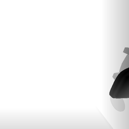
And here it is with a rendered dynamic stone "stone":
A cubic map for static geometry is cached and not created every frame, because the renderer knows that the light source is not really moving (although it is marked as Movable). If the source is animated, then the renderer each frame renders a “cached” cubic map with all static / stationary geometry, and then adds dynamic props to the shadow map (this picture is from another test that I conducted specifically to verify this):
The only static light source does not appear at all in the list of draw calls. This confirms that it does not affect the dynamic props and, through the baked light map, affects only static props.
I will give you advice: if there are stationary sources of lighting in the scene, then before performing the profiling in the Editor, bake all the lighting (at least I’m not sure what the launch of the game does as “standalone”). It seems that otherwise Unreal treats them as dynamic sources, creating cubic maps instead of using shadows for each object.
Now we will continue to study the process of rendering the frame in the Unreal engine, having considered the generation of the lighting grid, the preliminary passage of the g-buffer and the lighting.
Lighting purpose
The renderer then switches to the compute shader shader to link the lighting to the 3D grid ( ComputeLightGrid pass) in a manner similar to clustered shading. This lighting grid can be used to quickly determine the sources of light that affect the surface depending on its position.
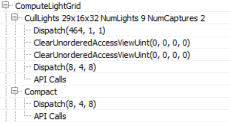
As the name of the passage suggests, the grid of illumination of visible space has dimensions 29x16x32. Unreal uses a screen space of 64 × 64 pixels and 32 parts of z-depth. This means that the number of XY dimensions of the lighting grid will depend on the screen resolution. In addition, judging by the name, we also assign 9 light sources and two reflection probes. A reflection probe is an “entity” with a position and a radius that reads the environment around itself and is used to create reflections on the props.
According to the compute shader source code (LightGridInjection.usf), the separation is carried out exponentially: this means that the z size of each grid cell in the visible space becomes larger with distance from the camera. In addition, it uses the parallelepiped of each cell aligned with the coordinate axes to perform the intersections of the limiting volumes of the light sources. To store the indices of light sources, a linked list is used, which is converted into a solid array in the Compact passage.
This illumination grid will be used for in-pass volumetric fog calculations to add light scattering in the fog, in the environment reflection pass, and the translucent rendering pass.
I noticed another interesting fact: the CullLights pass begins with clearing Unordered Access Views for the lighting data, but it uses ClearUnordered Access ControlUint for only two of the three UAVs. For the rest, it uses the compute shader, which sets the value manually (the first Dispatch in the list above). Obviously, in the case of buffer sizes larger than 1024 bytes, the source code prefers to use cleanup using the compute shader instead of using the API cleanup call.
Volume fog
This is followed by volume fog calculations, in which the compute shader shaders are used again.

In this passage, the permeability and the scattering of light in the volume texture are calculated and stored, which allows a simple calculation of the fog using only the surface position. As in the previously performed illumination destination, the volume “fits” into the visibility pyramid with the help of 8 × 8 tiles and 128 depth gradations. Gradations of depth are distributed exponentially. They move the near plane a little to avoid a large number of small cells close to the camera (this is similar to the Avalanche Studios cluster shading system ).
As in the volume fog technology (LINK) of the Assassin's Creed IV and Frostbite engine, fog is calculated in three passes: the first ( InitializeVolumeAttributes ) calculates and saves the fog parameters (scattering and absorption) into the volume texture, and also saves the global emission value into the second volume texture . The second pass ( LightScattering ) calculates the scattering and attenuation of light for each cell, combining shaded directional lighting, sky lighting, and local light sources assigned to the texture of the light volume in the ComputeLightGrid aisle. He also applies temporal anti-aliasing (antialiasing, AA) to the output of the compute shader (Light Scattering, Extinction) using the history buffer, which is itself a 3D texture, improving the quality of the diffuse lighting in the grid cell. The final pass ( FinalIntegration ) simply performs the raymarching of the 3D texture along the Z axis and accumulates the diffuse illumination and permeability, saving the result in the process to the appropriate grid cell.
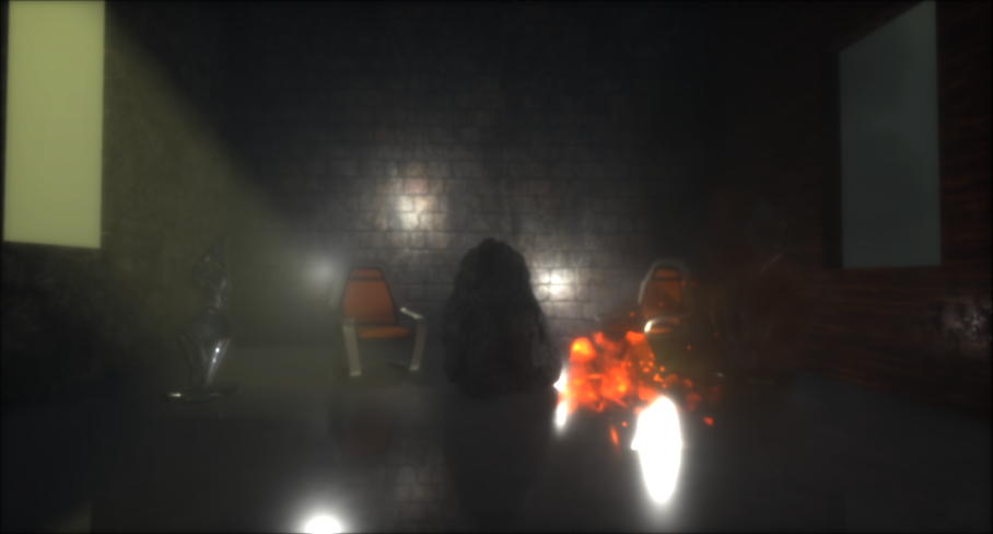
The finished volume buffer with light scattering is as follows. In it you can see the pillars of light due to the directional sources of illumination and local sources dissipating in the fog.

G-Buffer Pre-Pass
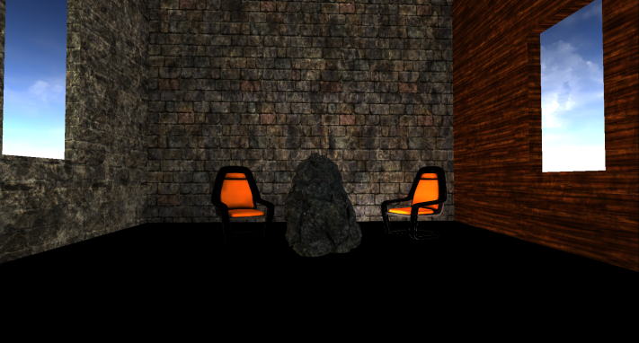
This is followed by a proprietary version of the preliminary pass of the Unreal G-Buffer, usually used in deferred rendering architectures. This pass is needed in order to cache the properties of materials into a multitude of target renderers in order to reduce redrawing during costly calculations of lighting and shading.
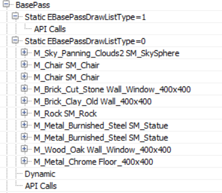
In this passage, all opaque props are usually rendered (static, moving, etc.). In the case of Unreal, the sky is also rendered first! In most cases, this is a bad decision, because the sky is later redrawn by other props that are closer to the camera, that is, the work turns out to be superfluous. However, in this case, this is quite normal, because the preliminary buffer of the Z-buffer previously performed by the renderer eliminates the sky redrawing (and most of the redrawing in general, at least for opaque props).
Here is a list of target renders to which the g-buffer pre-passes are recording.
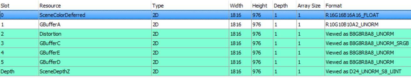
The depth buffer is used only for the z-test, it was already filled in the preliminary pass of the z-buffer, and now the renderer does not write anything to it. However, the renderer writes to the stencil buffer in order to mark those pixels that belong to the rendering opaque geometry.
The contents of the g-buffer may depend on the render settings. For example, if the renderer has to write a speed to the g-buffer, then it will take GBufferD and the data will be moved. For our scene and rendering path, the g-buffer has the following scheme.
 |  |
| SceneColorDeferred : contains indirect lighting | GBufferA : world space normals stored as RGB10A2_UNORM. It seems that no coding is used |
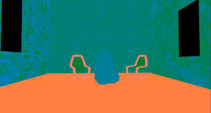 | 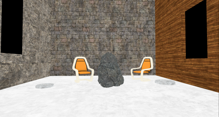 |
| Distortion : various materials properties (metalness, roughness, reflection intensity and shading model) | GBufferC : Albedo in RGB, AO in alpha channel |
 |  |
| GBufferE : own data depending on the shading model (for example, subsurface color or tangent vector). | GBufferD : Baked Shading Indicators |
 | |
| Stencil to mark opaque props |
It is worth noting that all the opaque props in the scene (except for the moving stone and the sky) sample information about the illumination from three atlases with mip levels that cache the irradiation, shadows and surface normals:


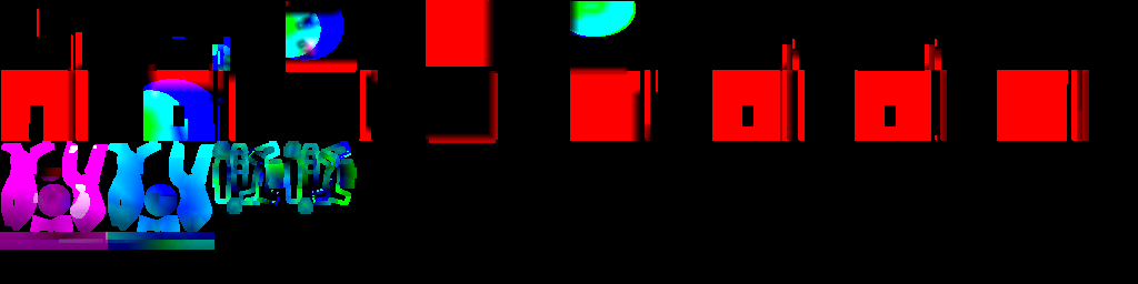
And again the simulation of particles The
simulation of particles was the first action performed in the frame, it was a passage that recorded positions in the world and the speed of the sprites of the particles. It occurs in the frame so early that the renderer does not have access to the depth and normal buffers to calculate collisions in the video processor, so it is time to go back and re-run the simulation for those particles that require it.
Rendering speeds
By default, Unreal writes the speed of the moving props to a separate R16G16 format buffer. In the future, the speed will be used for motion blur (for motion blur) and for all effects that require re-projection (for example, for temporal smoothing). In our scene, only a stone is marked as a moving object, so it is the only render to the velocity buffer.

Ambient Occlusion
After receiving all the information about the materials, the renderer is preparing to proceed to the lighting stage. But first he needs to first calculate the ambient occlusion in screen space.
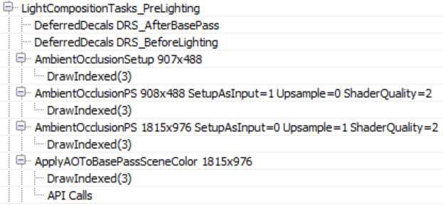
There are no deferred decals in our scene, but if there were, then I assume that the empty passages of DeferredDecals would change the properties of some materials in the g-buffer. Ambient occlusion in screen space is calculated in two passes - in a quarter resolution and full screen. The AmbientOcclusionPS 908 × 488 pass calculates AO using a quarter-sized normal resolution buffer created in the AmbientOcclusionSetup pass , a Hi-Z buffer created by the renderer earlier and random vector textures from which depth / normal buffers will be sampled. In addition, when sampling textures from random vectors, the shader adds small distortions to each frame in order to emulate supersampling and gradually improve the quality of the AO.

Then, the AmbientOccPSPS 1815 × 976 pass calculates the full screen, with a higher resolution, with AO and combines them with a quarter resolution buffer. The results are quite good even without the need to pass blur.
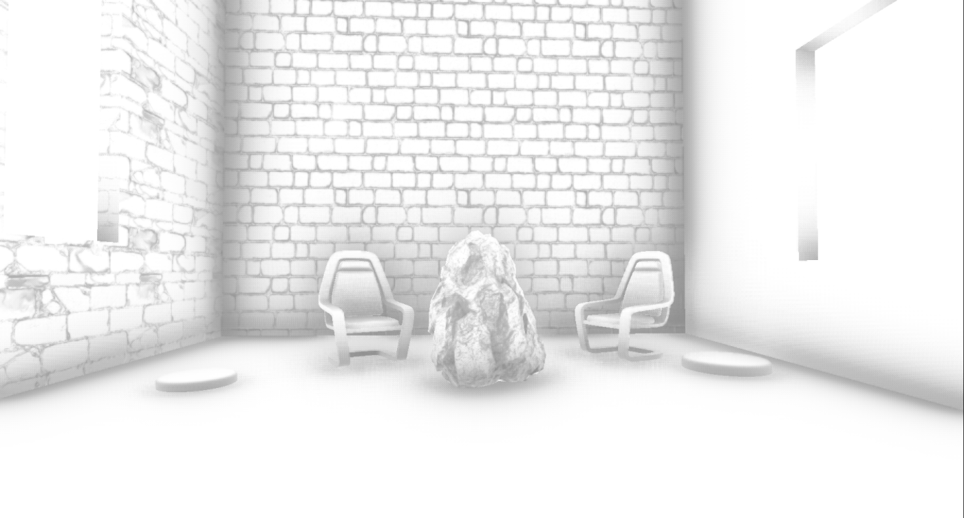
Finally, the full-resolution AO buffer is applied to the SceneColourDeferred buffer (which is part of the above G-buffer), which so far contains indirect (ambient) scene lighting.
Lighting
Before starting a discussion on lighting, it is worthwhile to step aside a bit and briefly talk about how Unreal illuminates translucent objects, because soon we will meet often with this system. Unreal's approach to lighting translucent surfaces is to bring the lighting into two 64x64x64 RGBA16_FLOAT volume textures. Two textures contain light (shaded + attenuated) in the form of spherical harmonics that reach each cell of the volume (TranslucentVolumeX texture) and approximate the direction of light from each light source (TranslucentVolumeDirX texture). The renderer stores 2 sets of such textures, one for props that are close to the camera and require high-resolution lighting, the second for more distant objects, for which high-resolution lighting is not so important. It uses a similar approach.that is, writing to a cascading shadow map, in which more texels are located closer to the camera than away from it.
Here is an example of volume textures for translucent lighting close to the camera with only a (shadowed) directional source.

These volumes of translucent lighting do not affect opaque props, they will be used later to illuminate translucent props and effects (particles, etc.). However, they will be filled in the aisle lighting.
Let us return to the direct illumination of opaque props - now the renderer can calculate and apply lighting to the scene. With a large number of light sources, this list of draw calls can be quite long. I have deployed only the most important parts.
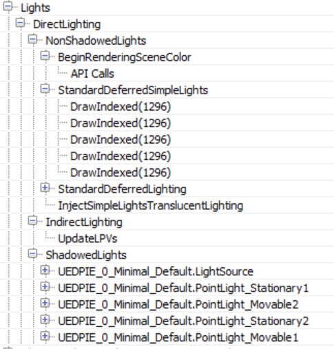
Light sources are processed in two groups, NonShadowedLights and ShadowedLights . The NonShadowedLights group includes simple sources of illumination, for example, the usual sources used for particle effects, and not casting shadows in the scene. The difference between them is that conventional sources of scene illumination use the depth boundaries test when rendering to avoid illuminating pixels beyond the approximate amount of illumination. This is implemented using specialized driver extensions.. Illumination accumulates in the above-mentioned SceneColourDeferred. Another difference is that simple light sources do not write at all to the volumes of translucent lighting (although it seems that this feature is provided in the renderer code, so perhaps this parameter can be enabled somewhere).
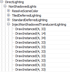
Interestingly, in the case when the number of shadowless (and non-static) visible light sources in the scene exceeds 80, the renderer switches from the classic deferred shading mode to the tile deferred lighting mode.

In this case, the renderer uses the compute shader to calculate the lighting (only for such light sources), passing the lighting data down to the shader through constant buffers (I thank wand de for pointing this out to me.). In addition, it seems that switching to tiled deferred lighting and using the compute shader shader to apply all sources of lighting in one pass only affects direct lighting. The InjectNonShadowedTranscluscentLighting pass still adds all the light sources separately to the amounts of translucent lighting (each creates a separate draw call):
The ShadowedLights pass handles all shadow-casting light sources, both stationary and moving. By default, Unreal processes each shadow casting light source in three steps:
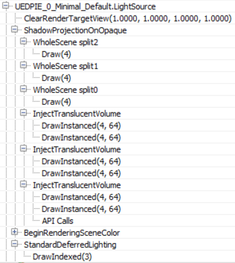
First, it calculates the shadows of the screen space ( ShadowProjectionOnOpaque ), then adds the effect of lighting to the amount of translucent lighting ( InjectTranslucentVolume ) and finally calculates the lighting in the scene ( StandardDeferredLighting ).
As stated above, for this scene the case of directional lighting, the shadow information contains only Split0. The result of the shadow calculations is written to an RGBA8 buffer the size of a screen.
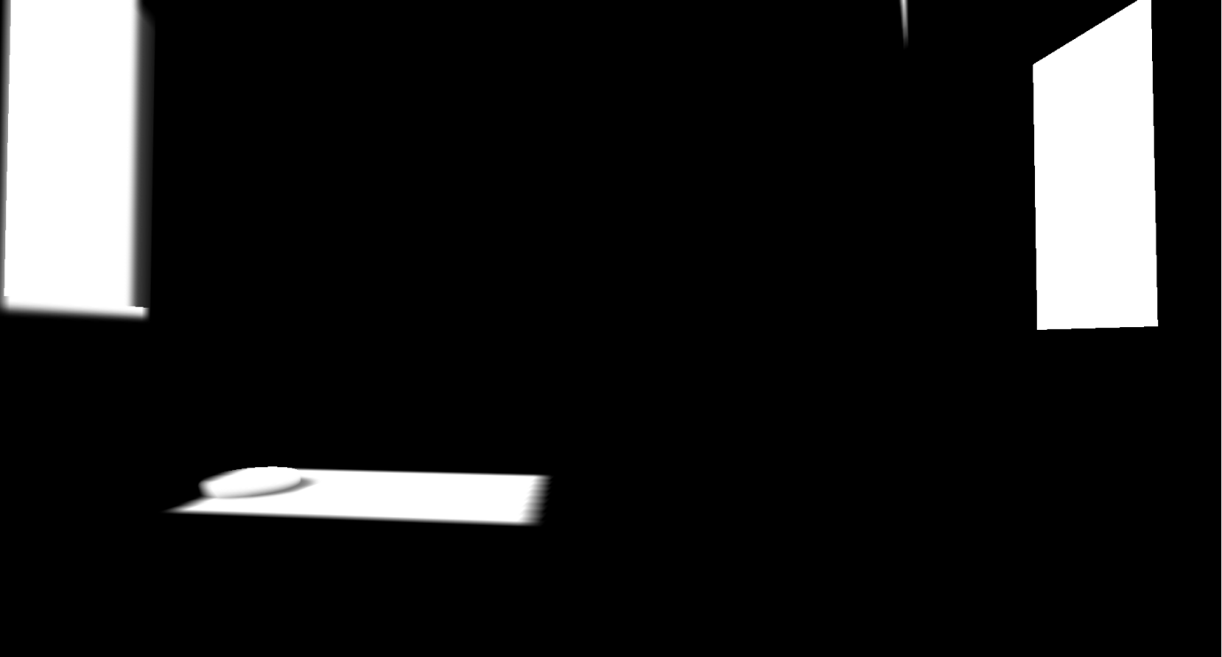
The next stage ( InjectTranslucentVolume ) records the effect of directional illumination for both stages in the above-described amount of translucent illumination (two calls per InjectTranslucentVolume pass ). Finally, the StandardDeferredLighting pass calculates and records the lighting by the shadow buffer mask of the screen space into the SceneColorDeferred buffer.
It appears that local sources use the same order to project shadows into the screen space buffer, adding lighting to the amount of translucent lighting and calculating the lighting with writing to the SceneColorDeferred buffer .

Both types are treated roughly the same way, the difference between mobile / stationary local sources is that mobiles add lighting with shadows to the amount of translucent lighting, and, of course, that for shadows mobile sources with shadows use a cube map rather than an object atlas .
All light sources use one target render of the shadow buffer of screen space, clearing the corresponding parts for the shadows of each source (I suppose this is done to save memory).
Upon completion of the aisle coverage, SceneColorDeferred contains all the accumulated direct illumination of the scene.
It is worth noting that despite the fact that the renderer created a grouped / clustered data structure in advance (lighting assignment pass), it is not used at all during the lighting pass of opaque geometry, using traditional deferred shading instead with separate rendering of each light source.
As a final step, the volumes of translucent lighting are filtered (for both stages) in order to suppress distortion when lighting translucent props / effects.

Illumination in image space.
Then full-screen reflections in the screen space are calculated (the target rendering format is RGBA16_FLOAT).
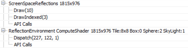
The shader also uses the Hi-Z buffer calculated at the beginning of the frame to accelerate the calculation of intersections by selecting the Hi-Z buffer mip level during raymarching based on the roughness of the surface (i.e., making the ray tracing for rough surfaces coarser because the details invisible in their reflections). Finally, in each frame, oscillations are added to the initial position of the beam, which, combined with temporal smoothing, increases the quality of reflection display.
The shader uses the target render of the previous frame to sample the colors when a collision is detected during raymarching, this can be seen from the volume fog in the reflections, as well as from the reflected transparent props (statues). Also on the right under the chair you can see traces of the effect of particles. Since we do not have the correct depth for transparent surfaces (to calculate correct collisions), reflections are usually stretched, but in many cases the effect looks quite convincing.
With the help of the compute shader, reflections in the screen space are applied to the main target renderer ( ReflectionEnvironment pass ). This shader also uses reflection reflections captured by two reflection probes in the scene. Reflections for each probe are stored in cubic maps with mip levels:
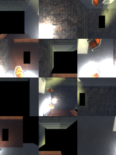
Environment reflection probes are generated when the game starts and capture only static / stationary geometry (note that the animated stone is not on the above cube maps).
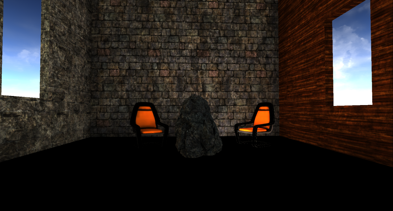
Our scene with applied reflections in screen space and environment reflections now looks like this.
Mist and Atmospheric Effects Mist and atmospheric effects
follow if they are also included in our scene.
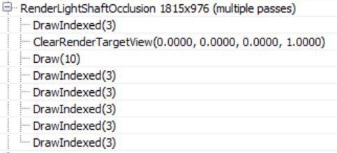
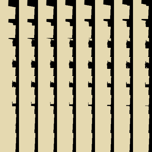
First, a quarter-resolution overlap mask is created, which determines which of the pixels will be received by the lighting columns (which apply only to directional lighting in the scene).
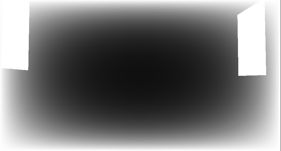
Then the renderer begins to improve the quality of the mask using temporal anti-aliasing and applies three passes of blur to create this mask (I had to process the mask because it was almost completely white):

From this capture of the video processor's actions it is not quite clear to me why a temporary AA is applied to the mask before blurring, because the final result has a very low resolution. Perhaps, to clarify this, more examples of use in different environments will be required.
Before the fog and the lighting columns are added to the scene, the renderer takes a breather and applies atmospheric effects (in full resolution) to the main target renderer.
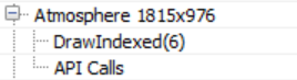
It looks like a complete scattering calculation using pre-calculated transmittance, irradiation, and inward scattering, similar to the work of Bruneton .
Our scene is in the room, so, unfortunately, the effects of the simulation are not too noticeable.
Finally, the renderer uses an exponential fog and lighting columns in the scene.
The shader uses the volume fog volume texture created by several nada passes, performing a sampling based on the position of the opaque geometry. She also applies the mask of the lighting columns calculated above.
Transparency rendering
After the fog is applied to the opaque props, the renderer is assumed to be a translucent geometry and effects.
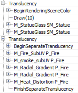
I added two glass statues to the scene that are rendered first, using ordinary alpha blending on top of the main target render.

These two transparent props are well located in the scene, they are influenced by local and directional light sources, reflections of the surroundings, fog, etc. By default, the renderer uses a high-quality shader for rendering transparent props, which, among other things, samples pre-calculated atmospheric simulation textures, baked lightmap data, translucent light volumes containing light from directional and local light sources, and cubic light emission probe maps. All this is used to calculate the lighting. However, I did not see that the shader reads the texture of the volume of volume fog, it seems that it only calculates the fog based on the height / distance, maybe I missed this parameter somewhere. Distance dependent fog, like atmospheric scatter, is computed in the vertex shader.
The renderer writes the effects of particles into a separate target render (full resolution).
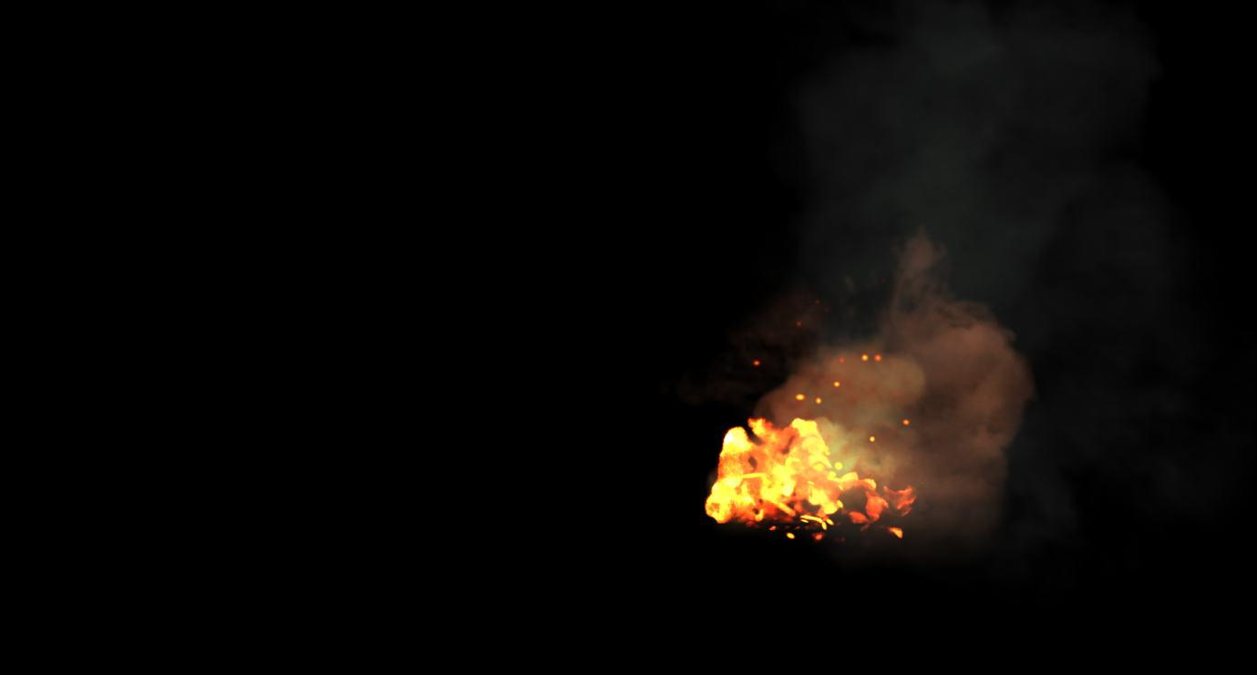
As in the case of transparent props, the atmospheric scatter and fog for them are calculated in the vertex shader. In addition, with certain settings of the particle system, the renderer can use for lighting particles the volumes of translucent lighting (in one of the cases I saw how it does it in a pixel shader).
Before completing the processing of transparency, the renderer performs one more pass to calculate the refractions.
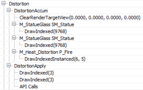
Both transparent props and particles (which should provide refraction) are rendered again to write to the full resolution buffer with distortion vectors, which will later be used to calculate the refraction (I processed the image so that the vectors are better visible). Stencil buffer is also active on this pass, which marks pixels that require refraction.
During the diffraction calculation pass ( DistortionApply ), the renderer reads the contents of the main target render (which is currently available) and the distortion vectors, and then writes a strange texture of the refractions.
Since the stencil buffer is active, marking the pixels that receive a refraction, the renderer does not need to clear the texture.
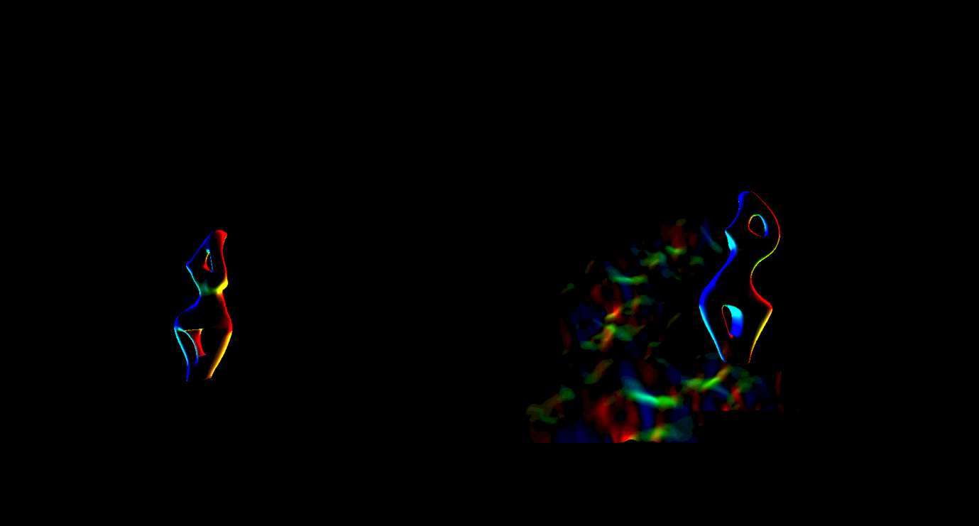
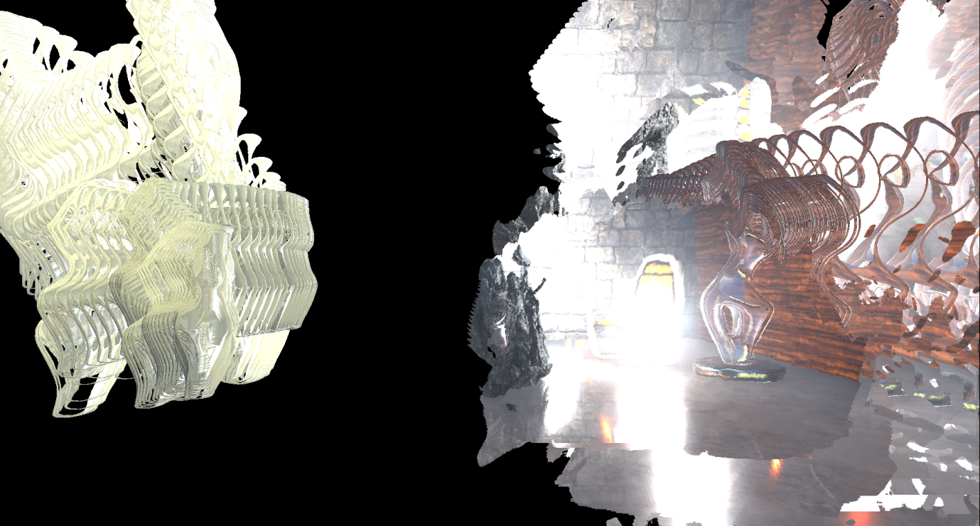
As we have said, the last pass of the refractions simply copies using the stencil buffer the texture of the refractions into the main target render.
You may have already noticed the refraction in the right-hand seat caused by particles that we have not yet applied. For transparent props, the refraction is rendered after rendering the props.
The next pass ( BokehDOFRecombine ) finally applies particles to the scene. This is a simple shader that does less than can be solved by the name of the passage (perhaps it depends on the rendering settings).

Post processing
The last part of the frame processing process includes several post-processing passes, which I will briefly review.
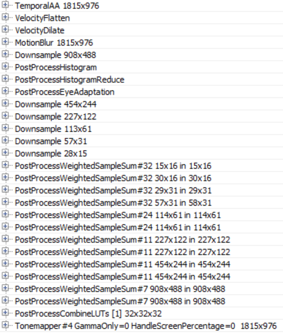
When configuring our scene, the renderer applies temporal smoothing, motion blur, automatic exposure, bloom, and tonemapping to the main target renderer.
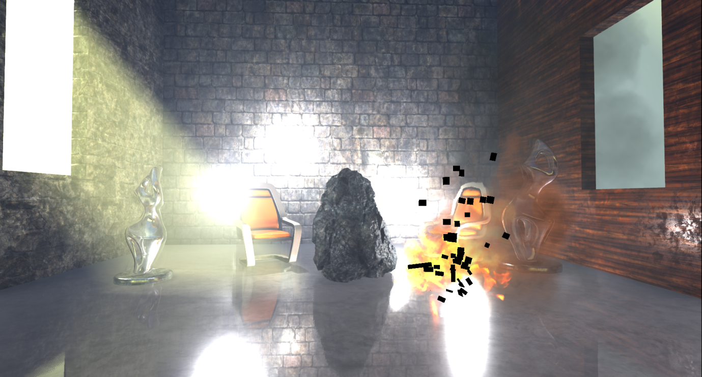
Temporary Smoothing Unreal uses a history buffer for gradually accumulating samples, after which it is rendered in two passes. In the first pass, pixels that are not in the stencil buffer (in our case, these are some of the particles) are applied to a temporary AA using the main target render, history buffer and velocity buffer for re-projection:
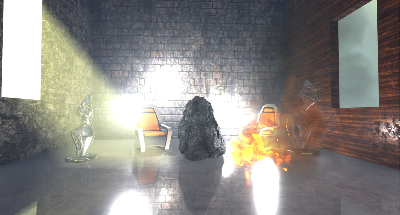
Then a similar passage of temporary AA is performed for the parts in the stencil buffer, creating the finished image with anti-aliasing:

The difference between these two passes of the time AA is that the former uses the mix ratio (feedback) between the history buffer and the current target renderer, which is variable and may depend on pixel brightness, distance transmitted by the scale renderer, etc. (based on parameters), and the second pass uses a constant mixing factor of 0.25: this means that the final pixel with anti-aliasing will mainly consist of the current sample. I think this is done to reduce the effect of the “ghostness” of fast-moving particles, for which we have no information about speed.
This is followed by the creation of motion blur, preceded by a leveling and speeding aisle.
In our case, the motion blur effect is not too noticeable, because the camera is static and the only moving prop that has speed is a stone (and it is already a little blurred due to movement and temporal smoothing).
To implement autoexposure (eye adaptation), the renderer creates a histogram of the illumination of the current scene using the compute shader. The histogram groups the brightness of pixels and calculates the number of pixels belonging to each brightness group.

The advantage of this approach is that we can easily skip over those areas of the image that contain very dark or very bright values and create a more reasonable approximation of the average illumination of the scene. Using this medium illumination, the renderer can calculate the adaptation of the eye, adjusting the exposure accordingly (bright images lead to a small exposure, and darker images to a large one).
To implement the Bloom effect, several passes are used to reduce the resolution, in which Gaussian filtering is applied, and then several operations of increasing the resolution and combining (the image is changed in such a way as to make it clearer without controlling the exposure).
In the PostProcessCombineLUTs pass, a geometric shader and a rather long pixel shader are used to create a lookup table for the color scale (volume texture 32x32x32 RGB10A2). The lookup table will be used during the tonemapping stage:

The last frame pass ( Tonemapper ) combines the previously calculated bloom with the main target render, adjusts the image exposure using the eye adaptation previously calculated, and then passes the color through the color scale lookup table to create the final pixel color:

Summarize
It should be emphasized that this is just one rendering path, it can be influenced by many parameters and settings, and in fact we have considered the very basics.
Overall, this turned out to be an interesting exercise, despite the fact that I rather learned what the renderer is doing, and not how it does it. A lot of things have remained unexplored and I want to return to this topic again.
The Unreal source code is not well documented, but it is quite clear and understandable. Following the list of draw calls, it is very easy to find the corresponding code. However, in many cases it was quite difficult to understand from the source code what the shaders do, because they actively use conditional compilation. For convenience of studying and performance profiling, it would be nice to have some intermediate cache of processed and ready-to-compile specialized shaders (the names of which are added to the list of draw calls).
It seems that by default the Unreal renderer focuses on creating high-quality images. He actively uses data baking (surroundings, lighting, volumes, etc.) and applies temporal smoothing to significantly improve image quality.
If there are a lot of props in your scene and not many opportunities to block them (for example, a large number of large overlapping objects), then you should carefully consider the passage of the calculation of overlaps. In addition, refractions on transparent props and particles lead to double rendering. Finally, many stationary or moving local light sources affect the lighting stage because they are rendered individually (and contribute to the cost of adding lighting for transparency and volume effects).
In conclusion, I would like to thank Baldurk for the excellent RenderDoc tool and Epic for revealing the Unreal source code for use, study and learning.
Source: https://habr.com/ru/post/341080/
All Articles