On the issue of strangeness and the impossible
The engineer should not waste time saying “This can not be”, because it has already happened. He should look for an objective cause of what is happening.Unfortunately, I could not find an exact quote, so you see it in my interpretation.
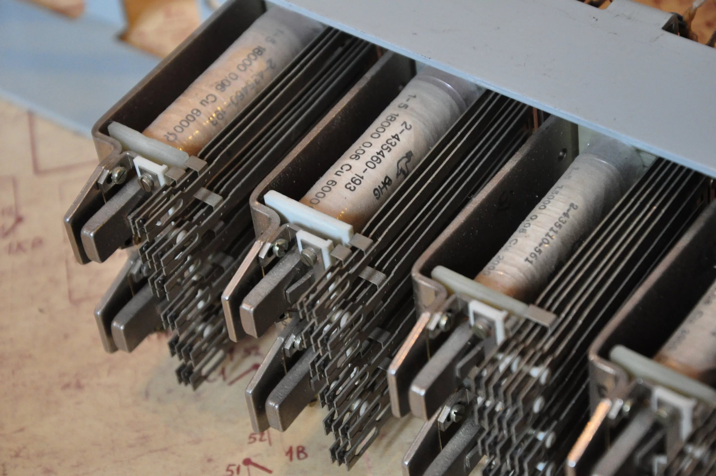
Let's continue the story about interesting defects in the field of electronics. Today we will talk about the "industrial" network in the PBX (shown in KDPV) based on the RS485 interface.

Further in the story abbreviations will be actively used, but it is not necessary to be frightened, their decoding will be given in brackets, so welcome under the cat.
A long time ago (about 8 years ago), when I was an entrepreneur in the field of communications in the Tver region, I had the opportunity to realize (in some ways, for that time) a revolutionary idea to modernize the existing ATSK100 / 2000 (Automatic Telephone Station of the Coordinate) on the basis of me by the time of the development of APT (Electronic). By the way, I still remember a trip to the department of the Ministry of Communications, where his representative was perplexed: “Why would we spend money (at the rate of $ 10 per number) to upgrade the station, which we will replace with digital in two years (at the rate of $ 70+ for number) "(my explanation is in brackets). Using third-party resources, the resistance of the department was overcome and the modernization was carried out. 8+ years have passed since then, the upgraded station functions quite successfully for itself, and talk of replacing it (and its neighbor) has not moved into the area of practical solutions, which seems to hint ...
')
So, an integral part of the project was the replacement of the checkpoint (Code Receiver), located as part of the AIS (Subscriber Query) with their electronic version, which, in addition to the main functions, had to exchange with the main BE (Electronic Block) information about the status of AK (Subscriber set). This means that a communication channel was needed, which was supposed to work in ATC conditions, and these are rows of iron cabinet cabinets in which the relay inductance is constantly switched to Henry units at a voltage of 60 Volts.
- this is so that you understand that I was not mistaken in writing the inductance nominal.
For the one who is in the subject, everything is clear, I will explain to the rest that under such conditions the jamming environment in the station is very tense. There was no talk of wireless communication right away, but from the wired options a bit - a serial interface, either as a current loop or as 422/485. Since the connection of one main unit with 13 (10 + 3) checkpoints was required, a point-to-multipoint connection was needed, so the current loop dropped out of the distance. It is a pity, according to my observations, a correctly designed current loop has no equal in terms of noise immunity, but nothing can be done, the one-to-many topology is not a strong place for this technology.
It is also necessary to take into account the design features of the station - the entire installation of the connections (and there are quite a few of them in the PBX) is carried out using cable growths over the cabinets (2.5 meters high, by the way) - the horizontal blue line on the CRLS, and the replaced gearbox is located at the bottom of the cabinet (vertical blue line there), and this is not subject to change. Note that in the picture you do not see the checkpoint, it is located from the back of the cabinet, where the ISS stand, I did not find the photo on the right side, but it stands exactly below. This circumstance should be considered when designing a network in terms of the design features of the interconnecting cable. The choice between 422 and 485 was not difficult - the work protocol allows for a simplex method, therefore 485 is quite acceptable and has fewer wires.
Next, the UART-RS485 converter is installed on the EKPP, the type of cable for communication is chosen - FC10 (I actively used it in other projects and it is quite convenient in installation, and also decent wave), taking into account the desirability of sequential bypass of nodes in the topology, 2 connectors are installed on the EKPP - input and output. The devices are manufactured, mounted on the PBX, operate offline, and the installation of the communication network must begin.
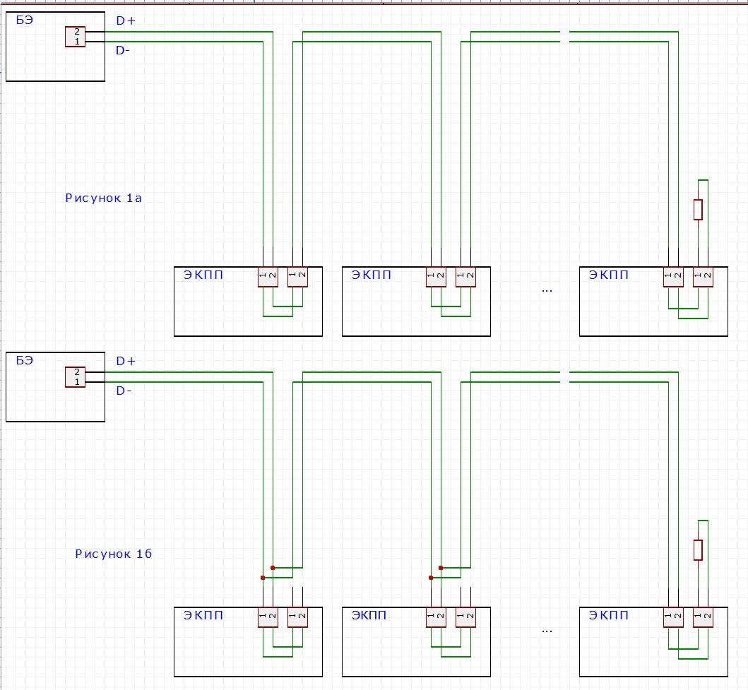
Initially, the sequential bypassing topology shown in Figure 1a) was planned, but its drawbacks are obvious at a glance — the vulnerability to node deletion. The option of parallel connection of cables indicated in Figure 1b) is no better, since the cable will have to be mounted “on site” and if there is a need for repair there will be problems, and mounting two cables to one connector (for this type of cable and connector) cannot call a convenient solution.
Therefore, we come to a variant with taps. Yes, I know that this option is not recommended for use and I understand perfectly why this is done, but this is just a wish, not a categorical imperative. Therefore, taking into account that:
0) the network as a whole is not too long (each branch is 20 meters);
1) bends are not too long (about 2 meters);
2) the speed is not too high (I don’t remember the exact figure now, not more than 115200 baud, and maybe even 9600);
3) converters are good with high noise immunity (AD);
4) a bundle of lands is dragged in the cable (in general, all the checkpoints are connected through a common plus - in telephony, the power is supplied with a grounded plus, but the mess is not spoiled with oil),
We conclude - you can try.
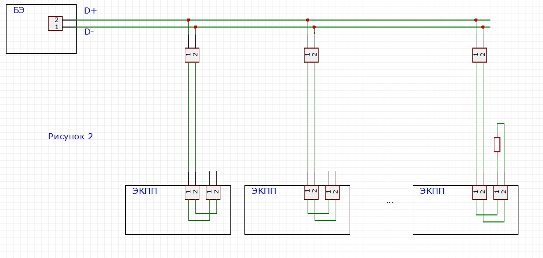
We make an experimental section, shown in Figure 2, check the waveform with an oscilloscope (the arrow is not ticking), start the exchange test (the vehicle (network tester) has been developed and manufactured in advance, checking the exchange with each PPC in the network segment) and for a week do not see any failure - all this means that we are lucky (although this luck was carefully prepared) and convenient installation did not lead to bad signals.
So far, we have seen a success story, and here it is a misunderstanding. Inspired, we collect the remaining network segments and (do not disappear as good) check them with the help of the aforementioned tester. In the process, we find that the exchange with the second EKPP does not work out (Figure 3a), and absolutely (that is, never), and with the rest everything is fine.
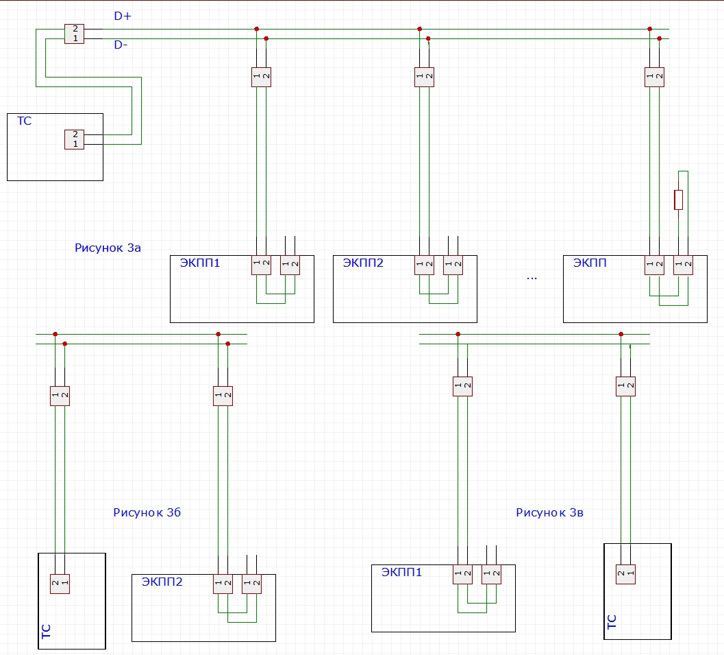
We make an assumption that the segment of cable or EKP cable is to blame, check under 3b scheme (in general, a completely unnecessary check, just not to go far) - the assumption is confirmed, the final touch is 3b scheme) and a sudden bummer - everything works, it means no cable . We assume that the checkpoint is to blame, but we checked them after the assembly, okay, sometimes we change 2 neighboring checkpoints in places (it’s easy to do this) and we are surprised to see that the defect remains in place, which means the checkpoint is not to blame. That is, it’s still a drop segment, we change two adjacent cable sections in places and (Bingo!) The defect moves after the cable. Very good, but how to explain the results of the test c) (I remind you that everything worked) as a possible cable defect is not clear.
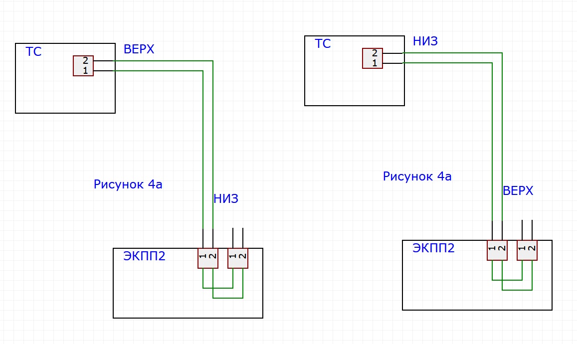
We isolate a suspicious cable segment and conduct tests of it - Figure 4 a) and b) and quite expectedly we get that the first option does not work, but the second one (this is when we turned the cable upside down) suddenly (but also expectedly) it functions.
But it can not be so! - but it is - it means that I just do not understand something. We formulate what exactly can not be - so that two identical devices behave differently at two identical ends of the cable. But two different devices at different ends of the cable can behave differently - we will look in this direction.
Therefore, the first question - are my devices the same? And it turns out that there is not - there is a terminating resistor on the tester (along with tensile), and at the checkpoint this unit is installed only at the far end of the network. I take the terminator from the last device, put it on the current checkpoint and everything starts working at any cable orientation, that is, at both ends of the cable segment. The first neponyatka disappeared, the devices are really different, I remove the terminator and continue research.
Now you need to understand the differences between the ends of the cable segment. Again, at first glance, this is impossible, because we have only 2 wires for receiving and transmitting (in fact, there is also a third wire - pulling in lands, but it cannot be affected so fatally), and they cannot stop working when cable reversal - the wire is either from one end to the other, or there is none at all. But the difference should be - take the cable and carefully look at it. And here comes the moment of truth.
As I indicated earlier, a flat cable with 10 wires was chosen for installation (no longer needed, but I did not have less, yes, maybe it does not happen at all). And you only need to carry 3 signals, there are extra wires. We, communicators, know for sure that “a pair for a conductor” (using two wires connected in parallel instead of one) is a good practice, because it reduces the resistance of a circuit section and improves the reliability of operation, this technique was applied for this case as well. Each of the signals was transmitted via two wires of the cable and the present circuit looks a little different from what I drew it earlier - see Figure 5a).

Then the cable segment may have a defect, shown in 5b) and if there is a connection in principle (at the expense of a working conductor), the cable has different ends (at the expense of a faulty conductor).
Well, now everything is simple. Unconnected on the other hand, the wire works as an antenna, collecting interference, which in the case of a terminator (and stretch marks) is extinguished, and in the absence of them, affects the receiver and disrupts the operation of the protocol. Call the cable segment and find out that, indeed, the edge connector did not pierce one of the wires of the data line (the connector is mounted on the cable using pinning - a very convenient and quick operation that does not require wire preparation and runs “at a time”, but, as it turned out, requires control). You can ask the question - why the receiver did not remove the interference, because the RS485 interface is differential and should be insensitive to common mode interference. The answer lies precisely in the nature of the defect - there is a transverse asymmetry of the cable, which dramatically increases the sensitivity to common mode interference.
Further, in order to detect such defects, a test device was introduced to allow using a switch to work with one of the wires of the data pair and all previously mounted sections of the communication network were checked, which allowed to detect two more defects of this kind that did not lead to a malfunction.
Here is such an instructive story that fully justifies the epigraph to the post.
Source: https://habr.com/ru/post/340390/
All Articles