Writing a three-dimensional retro shooter engine from scratch
I always liked the classic first-person shooters of the 90s. I would sit for hours at my
At that time, everyone wrote 3D engines from scratch, because there was no other way. But today, writing the logic of 3D rendering from scratch is likely to be a bad idea. Very bad. Almost like the invention of the wheel! With a huge number of 3D engines and libraries that are much more well tested and optimized than what you can do yourself, there is no reason for a reasonable developer to start writing his own engine.
If only…
')
Imagine that you can go back in the time machine back in the 90s, when there was no OpenGL or DirectX yet, there were no video processors. All you have is a CPU and a screen full of pixels. You have to write everything yourself.
If this idea seems interesting to you, then you are not alone: this is exactly what can be done on such a made-up console like the TIC-80.
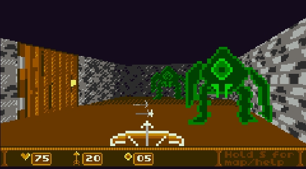
After writing the 8-bit panda , my first game for this console (you can read about it in my previous article ), I started looking for an idea for a new game. Therefore, I decided to set myself the task of writing a simple 3D engine from scratch and creating a minimal first-person shooter in it.
That's how I started writing FPS80.
In this article, I will describe the 3D rendering process in FPS80 and talk a little about all the trade-offs to ensure speed (and endless horrible hacks!) When implementing fast 3D rendering on this weak machine.
3D graphics basics
If you already know how 3D rendering works, then this section will seem boring to you. You can immediately proceed to the next section!
A full explanation of 3D graphics is too voluminous for this article, so we only briefly consider what is important for our purposes.
The fundamental idea of 3D graphics is to project 3D space onto a 2D surface (computer screen). In other words, one of the main tasks of the 3D engine is to find for a given coordinate (x, y, z) a point in the space of a 2D coordinate (x, y) of the place in which the point should be on the screen.

For this, 3D engines perform a series of transformations. Transformation is a brief definition of the expression "transformation from one coordinate system to another." Transformations can represent movement (movement, rotation, scale) and projection. Usually they are represented by matrices.
To calculate the screen position of a point, we first need to transform it by its model matrix M , translating it into the space of the world. Then we multiply it by a matrix of type V to take into account the position of the camera, which translates it into the space of the camera (or eyes). Then we apply the projection matrix P, which performs a perspective transformation that makes nearby objects large, and distant objects small. After this, a perspective division is performed, which translates points into coordinates of the screen (viewport):
p '= P * V * M * p
Applying this sequence of operations to a point is often called “projecting” a point. But scenes are made up of objects, not points, so the 3D engine does not only do this.
A 3D object consists of polygons. To render them, the engine usually divides a polygon into triangles, then projects each vertex of each triangle using the above formula, and then draws the resulting triangles of screen space on the screen. This process is called rasterization: it is a transformation from a vector shape (triangle) to a raster shape (the screen pixels themselves). But drawing the triangles in random order will not give good results. because it may turn out that the far triangle is drawn over the near one, therefore the engine should use the strategy for solving such a problem. Usually, it is solved either by pre-sorting polygons, or by creating a depth buffer, into which the depth of each pixel is written for display on the screen, so that you can know when and when you do not need to draw a pixel.
Add texture mapping and lighting, and this is another whole layer of math that the engine calculates to figure out the final pixel color.
Do we need full 3D?
Honestly, I started to implement the full process of creating 3D graphics, described above, but I realized that it would be too slow on TIC-80. As on older PCs, all mathematical calculations and rendering can easily overload the CPU and make the game slow. I wrote an example in which only four rotating cubes with superimposed textures were drawn, and even that was enough for the frame rate to drop below 10 fps. It became obvious that "full 3D" will not work. In particular, the “bottleneck” was fill rate , that is, the problem was basically not with the mathematics of projecting points, but with the time required to draw all the pixels of the triangles onto the screen, especially when doing this several times because occupy overlapping parts of the screen.
But do we need full 3D? In fact, it turns out that many of the old games of the 90s do not implement “full 3D”. Instead, they implement cunning graphics restriction mechanisms so that rendering it is less expensive.
So, here are the limitations that I imposed:
- The whole level is flat: no stairs, pits, balconies, second floors and all that. That is, the floor and ceiling are at a constant height.
- All walls have the same height, from floor to ceiling. And they are all opaque.
- The player can turn in any direction, but can not tilt his head up and down, as well as sideways. In other words, the camera has only one degree of freedom of rotation: the course or yaw .
- All objects are drawn as “billboards”, that is, 2D images rendered in 3D space in such a way that they are always directed towards the camera.
- There are only point sources of light. One of them is always in the chamber (like a torch in the hands of a player). Others can be created for a short time, for example, for the effects of explosions.
How will these limitations help us?
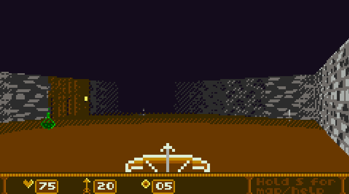
The fact that the floor and ceiling have a constant height and that all walls go from floor to ceiling (and the player cannot look up / down) creates a wonderful property that will help us very much: in each X position of the screen there will be no more than one wall. In other words, all visible walls occupy the middle part of the screen and two different walls will never occupy the same X coordinate:

Select the walls in different colors to make them more visible:

As you can see, in the screenshot there are six walls (the door is also a “wall”), and all of them are very conveniently located on the screen: each X coordinate of the screen corresponds to only one wall.
This is very useful for us, because we can render the walls in two stages:
- Determine which wall should be in each X coordinate (in other words, build a map from X coordinates to the walls).
- We go around (only once!) All the X coordinates, drawing for each the necessary part of the wall.
For entities (objects) - monsters, projectiles, columns, fountains, trees and the like - we will use the frequently used billboarding technique. Entities will not be represented by a real 3D object, we will simply draw a flat 2D image in a 3D coordinate as a cut out of cardboard. This method is very inexpensive when rendering.
Our projection procedure
Even in our very simplified 3D world, we still need to project points from 3D space to 2D. However, our limitations make mathematical calculations much easier and faster to process. Instead of performing the full matrix multiplication, we can do a much simpler way: we define the unchanged parts of the matrix calculations (those that do not depend on the position of the player or object), and then simply insert the calculated values into the code. I will look at all this briefly, but if you are interested in detailed calculations, this is how they are derived .
Remember the formula:
p '= P * V * M * p
Where p 'is the screen coordinates (output), and p - world coordinates (input). In our simple model, M is the identity matrix (everything is represented in world space), that is, it turns into:
p '= P * V * p
The visibility matrix V can be calculated by simply moving and rotating the camera, which are limited to rotation only along the Y axis. If the rotation is R and the movement is T, then:
p '= P * R * T * p
The projection matrix P can be calculated in advance, because it depends only on the field of view and the near / far cut-off planes, which are constant throughout the game. Having simplified the calculations, we will end up with a fairly straightforward (if everything is set as hard as possible in the code) the projection function:
function S3Proj(x,y,z) local c,s,a,b=S3.cosMy,S3.sinMy,S3.termA,S3.termB local px=0.9815*c*x+0.9815*s*z+0.9815*a local py=1.7321*y-1.7321*S3.ey local pz=s*xz*cb-0.2 local pw=x*sz*cb local ndcx,ndcy=px/abs(pw),py/abs(pw) return 120+ndcx*120,68-ndcy*68,pz end Look at these magic numbers: 0.9815, 1.7321, etc. All of them are taken from pre-prepared matrix calculations. By themselves, they have no intuitive meanings (so I didn’t even turn them into constants).
The variables cosMy , sinMy , termA and termB are calculated from the current movement and rotation of the camera before calling the function, because it is enough to calculate them only once for all points.
Wall rendering
At the first stage, we will use an array, which we call H-Buf (horizontal buffer) , which determines what will be drawn in each X coordinate of the screen. "H-Buf" is a non-standard designation, I came up with it myself. He is called H-Buf because he is H (horizontal) and he is Buf (buffer). I am not very original in making up names.
The TIC-80 screen contains 240 columns (240x136), so H-Buf has 240 positions. Each position corresponds to the X coordinate of the screen, and contains information about which part of the wall should be drawn there. In order to simplify everything, I will call it not “a piece of a wall one pixel wide”, but “a wall cut” . That is, each position in H-Buf gives information about which wall section to draw in each X coordinate of the screen:
- wall (object): - this is a link to the wall that will be drawn in this slice.
- z (float): - the z coordinate of the screen space (depth) of this slice.
- and much more ... but let's not talk about it yet!
This is enough for us, at least for the first stage! So, we need to go around all the walls of the level (we will soon talk about how to make this operation more efficient). For each wall we:
- Use the projection function on its four corners to determine where it will appear on the screen: left x, right x, left-top y, left-bottom y, right-top y, right-bottom y, left z (depth), right z (depth).
- We go around each X coordinate (from left_x to right_x) of the wall and record the wall section in H-Buf, when its depth is less than the existing section in this position in H-Buf.
The first test “the depth of this slice is less than that of the existing slice” is called the depth test . It allows us to render the walls in the correct order - those closest to the player block the far ones. Here is the corresponding code snippet:
function _AddWallToHbuf(hbuf,w) local startx=max(S3.VP_L,S3Round(w.slx)) local endx=min(S3.VP_R,S3Round(w.srx)) local step local nclip,fclip=S3.NCLIP,S3.FCLIP startx,endx,step=_S3AdjHbufIter(startx,endx) if not startx then return end for x=startx,endx,step do -- hbuf 1 ( Lua) local hbx=hbuf[x+1] local z=_S3Interp(w.slx,w.slz,w.srx,w.srz,x) if z>nclip and z<fclip then if hbx.z>z then -- . hbx.z,hbx.wall=z,w -- end end end After performing this operation for each wall, H-Buf will contain the correct information about which slice to render at each X coordinate, that is, for rendering, we just need to render the correct part of the desired wall cyclically. Because of this, this approach turns out to be fast: when we draw walls, there is no delay, no extra work, we know for sure that we need to draw and touch only the pixels that need to be touched. We never have it so that first we draw a part of the wall, and then draw another wall over it (there is no redrawing).
Here is the rendering code. Notice how simple it is: for each X, we simply render the texture column at this X coordinate, and nothing more:
function _S3RendHbuf(hbuf) local startx,endx,step=_S3AdjHbufIter(S3.VP_L,S3.VP_R) if not startx then return end for x=startx,endx,step do local hb=hbuf[x+1] -- hbuf 1 local w=hb.wall if w then local z=_S3Interp(w.slx,w.slz,w.srx,w.srz,x) local u=_S3PerspTexU(w,x) _S3RendTexCol(w.tid,x,hb.ty,hb.by,u,z,nil,nil, nil,nil,nil,w.cmt) end end end We double the frame rate with a very strange trick.
Even though the TIC-80 has a resolution of only 240x136, filling the entire screen still takes quite a lot of the CPU power, even if we don’t waste time at all and know exactly what to draw. Even the fastest rendering algorithm on simple scenes produces about 30 fps, and on more complex scenes the frequency drops significantly.
How do we get around this problem?
We need to ask ourselves: is it really necessary to fill the entire screen? No, it is not required. The human eye “smoothes out” the flaws of fast-moving events (and people playing retro games are very lenient towards small visual glitches!), So we can speed up rendering by filling only half of the screen in each frame.
We will do the following:
- In even frames we will draw only even X coordinates.
- In odd frames, we will only draw odd X coordinates.
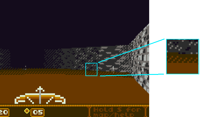
This process is also known as interlaced rendering . This means that in each frame we will actually render only 120x136 pixels, not full 240x136. We do not clear the screen in each frame, so the pixels that we will not draw will simply be saved as the remnants of the previous frame.
This causes small visible glitches, especially when moving fast, but in fact it works on the game, not against it, giving the retro feel of a television screen.
Here’s what we’ll actually render each frame (at least we’d see it if the other columns weren’t filled with pixels from the previous frame):
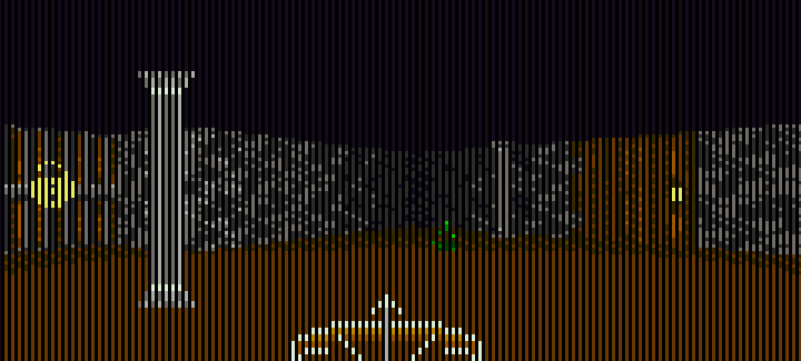
One frame of interlaced rendering. Non-rendered columns are left empty for clarity. In fact, they will be filled with the results of rendering the previous frame.
Rendering a wall cut
Great, now we are going to render the cut of the wall. We already know which slice to render, and we know where. All you need to do is determine which pixels to render in this column and what color they should be. How to do it?
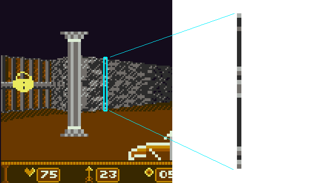
Wall slice (vertical column wall one pixel thick).
- Calculate the lighting falling on this slice, taking into account the sources of light and distance.
- Calculate the horizontal coordinate of the texture to cut the wall (with perspective correction).
- Calculate the top and bottom Y coordinates of the slice by interpolating the end points of the wall.
- Fill each pixel from top to bottom, which means determining the vertical coordinate of the texture (affine transformation), texture sampling, then modulation by lighting, and finally recording the pixel on the screen.
We can do with an affine transformation (instead of a perspective-correct transformation) for the vertical coordinate of the texture because the walls are always upright relative to the screen (this is guaranteed because the player cannot turn his head up and down, as well as sideways). If the situation were different, we would have to realize the correct texture imposition from the perspective of both horizontal and vertical texture coordinates, which would be slower.
Entity rendering (add stencil buffer!)
Well, the walls are fun, but the engine will not be a game without enemies. As I said earlier, enemies are rendered as billboards, that is, as floating images, always directed towards the player.

Entities rendered as billboards (always directed towards the camera).
However, these images are not just two-dimensional: they are drawn at a certain point in space, so they have depth . If the enemy goes behind the wall, the wall must be rendered in front of the enemy (the enemy must overlap the wall), and nothing else.
How to achieve this effect?
If we wanted to simplify everything, we could use the artist's algorithm (which is more like the absence of an algorithm): just draw objects backwards, while objects in the foreground would naturally draw over the objects from the background, providing the desired effect.
What is wrong with him? Its easy to understand. It's easy to write. But ... it is very slow, especially on TIC-80, limited in fill rate. With this implementation, we would spend a lot of resources on drawing beautifully textured and lit pixels, which would later be simply covered by other pixels.
And here we need to introduce a new buffer: stencil buffer. In 3D rendering, the stencil buffer is a screen-sized 2D surface that shows where you can and where you cannot draw. It looks like a filter. Each pixel in the stencil buffer can be “on”, that is, to say “blocked, not to draw” or “off”, that is, to say “freely, you can draw”. Depending on the implementation, the values may be reversed, but in our code we will use the value “true” to indicate the state “busy, do not draw”.
When the program “reads the stencil buffer” , this means that before drawing it checks whether the stencil buffer is “turned on” at each position. If this is the case, then it will not render the pixels above the existing pixel.
When the program “writes to the stencil buffer” , this means that when it renders something at a given screen position, it writes to the stencil buffer to indicate that this position is already taken and should not be redrawn.
So, here is what we do. Before rendering the walls, but after calculating the H-Buf, we draw the entities. The complete algorithm will be as follows:
- Clear stencil buffer.
- Calculate H-Buf.
- Render entities from front to back (read / write stencil, depth test in H-Buf).
- Render walls with H-Buf (read stencil).
When rendering each pixel of each entity, we write to the stencil buffer, prohibiting to render everything else on top of it. So we need to render in order from front to back . This means that everything we draw is final . This means no redrawing, we never waste the pixels drawn on the screen.
When drawing entities, we know their depth in the screen space and we know the depth of the wall in this position X (thanks to H-Buf!), So we can also perform a depth test of this column. This means that we correctly refuse to render parts of the entity that will then be hidden behind the wall (even though at this stage of rendering the wall is not there yet!). Again, we don’t want to waste a single extra pixel. They are very expensive for us.
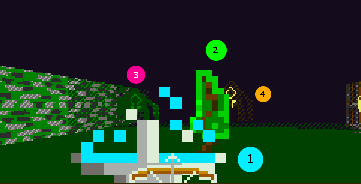
Here is an example of a scene with four overlapping billboards and the order in which they are rendered. The first is the fountain (number 1, the closest one), then the tree (2), then the green monster (3) and the orange monster (4, the farthest).
What about the floor and ceiling?
The floor and ceiling are rendered at the final stage of the process, because they are the only pixels left after rendering entities and walls. Everything is simple with the ceiling: it is just completely black, we fill these pixels by looking at the H-Buf and determining where the wall begins. Each pixel above it is black (but we still check the stencil buffer). Is done.
The floor is more complicated because it is necessary to apply the lighting effect: we want parts of the floor that are distant from the player to be darker.
But to calculate the lighting, we need to know the depth of each pixel of the floor. To determine it for each pixel is surprisingly simple, because we start in reverse order from the coordinates of the screen space to determine the coordinates of world space, and then determine the distance from the player to them. Moreover: we can calculate everything in advance manually and enter these magic numbers so that the procedure is very simple:
function _S3FlatFact(x,y) local z=3000/(y-68) return _S3LightF(x,z) end For given x, y pixel coordinates on the floor, the corresponding Z coordinate on the floor will be only 3000 / (y-68). I have no idea why, it just so turned out from calculations on paper. And we use this in _S3LightF to calculate the amount of light falling on this point, the corresponding modulation of the color of the floor.
This is what the floor lighting palette looks like. Notice that it gradually darkens with distance from the player:
Additional point light sources
We will provide support for temporary point lights for lighting effects, for example, when a player throws a fireball and it explodes:

The principle is the same: we calculate the distance in the screen space from the point drawn to the secondary light source (explosion) and take into account its effect.
Please note that we do not use this effect for constant lighting (for example, torches on the walls), because it is expensive and not too reliable. Since it is calculated in screen space, it actually does not take into account the rotation and movement of the camera, and it has unpleasant features and division by zero when the source is too close to the player.
Color Modulation and Dithering
TIC-80 allows you to work with only 16 colors, so how can we create lighting effects, making the pixels brighter or darker?
I used the following technique: I created three different “tones” that have four different shades, from dark to light. These tones can be modulated by choosing one of four shades each, plus black (color 0) as the darkest. As a result, we will have three "linear changes" - gray, green and brown:

clrM={ -- "" {1,2,3,15}, -- "" {7,6,5,4}, -- "" {8,9,10,11} }, They are set as simple arrays, so when we need to modulate a color for a certain amount of lighting, we just need to find the color and determine which other color of the same linear change to choose.
What about intermediate colors?
For them, I applied the strategy that was used in the old graphics hardware: dithering . Since we cannot have one pixel of an intermediate color, we will draw a pattern in which a part of the pixels will have one color, and the other part a different color. As a result, the eye will perceive them as an intermediate color:
Particle effects
To give the player a pleasant feedback when killing monsters or destroying objects, we will use simple particle effects:
These are just small rectangles simulated in world space and transformed into screen space at the rendering stage. For reasons of speed, they are not cut off and are not taken into account in the stencil buffer, but are simply drawn on top of everything else (a slight deviation from the principle of “not spending extra pixels”). Fortunately for us, interlaced rendering masks the fact that they are rectangles: since they quickly move and render each frame in different positions, they are broken up by interlacing into parts and look more “organic”.
Conclusion
In this article, we briefly reviewed the rendering process in the FPS80. I had no experience in writing 3D-engines from scratch, so I am sure that much could have been done better, and my explanations are largely erroneous. Contact me if you find an error (I can write to Twitter ).
Developing your own logic for 3D rendering turned out to be very interesting and informative. Especially funny was the need to squeeze every drop of speed from the algorithms. It gave me a (small) idea of how 3D engines were created in the 90s!
The FPS80 source code and rendering engine are laid out on github . Feel free to use them in your projects!
Note. : TIC-80 . TIC-80
surf . [tic.computer/play] Z . FPS80 Z . - TIC-80 ( ).Source: https://habr.com/ru/post/340234/
All Articles