Overview of one Russian RTOS, part 8. Work with interruptions
I am publishing the latest article from the first volume of the “Book of Knowledge” of the MAKS RTOS. I hope this informal guide will help you, colleagues, in case you have to work with this RTOS.
Previous articles:
Part 1. General information
Part 2. Core MAX MAX
Part 3. The structure of the simplest program
Part 4. Useful theory
Part 5. The first application
Part 6. Thread synchronization tools
Part 7. Means of data exchange between tasks
Part 8. Work with interruptions (this article)
Computer science teachers love to talk about the fact that there is work on the survey, as well as on interruption, after which they usually give a small example of interrupt handling and forget about the topic. Further, with real programming, you have to comprehend the basics of this business not with your own skin.
')
When programming in single-tasking systems, it is often possible to "get out" by working with equipment according to the survey. In multitasking systems, it becomes more difficult.
Consider the simplest example. Let there be a reception from a serial port with a terribly low speed of 9600 AML. Real speeds have long been in the region of 250 KBDO, but in order to avoid the desire to simply slow down to solve a problem, let's consider the very slow option.
In the serial port, one byte is at my favorite port setting of 10 bits (8 data bits, as well as start and stop). Total, comes 960 bytes per second. Round up to 1000. This is 1 byte per millisecond. Place events on the time axis.
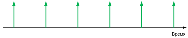
If the typical controller does not have time to process the next byte before the next one arrives, it will be overwritten by the new value coming from the line. Consider the essence of this on the diagram from the description of the controller STM32.

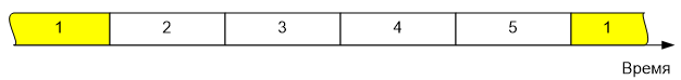
By default, tasks are switched 1 time in 1 millisecond. We will place on the time axis a case of sequential switching of five tasks.
Let the COM port be queried in task 1. Let's combine two pictures ...
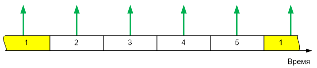
As you can see, 4 bytes from the serial port will come when the task waiting for them is inactive. There are controllers with a large hardware queue. For example, ESP8266 can accept 128 bytes in a hardware buffer. Such controllers consider the situation at all - task 1 will receive the data accumulated by the equipment. But, for example, all STM32 input buffer can take no more than one byte. And for them, working with a serial port in a multitasking environment, according to the death survey, is similar even at such “funny” speeds as 9600 bits per second.
The correct decision will be to add the bytes to the buffer memory so that the processing task takes everything that has been accumulated in bulk. As an option, perform some kind of preprocessing (for example, initial analysis of packets, if this is possible without any special delays) and transfer the already preprocessed parameters to the processing task.
Of course, the example of a serial port was chosen as the one closest to most readers. In fact, there are many more cases where polling is poorly acceptable even in a single-task environment and impossible in a multi-tasking environment. The first thing that comes to mind is maintaining engine speed. The real case is that the engine rotates at a speed of up to 5 thousand revolutions per minute, from it comes two feedback pulses per revolution.
One of the typical algorithms for measuring the rotational speed, requires measuring the period of the following pulses using a timer. That is, you need to take a timer reading at the time of arrival, and then restart the timer for a new measurement. If from the moment of arrival of the pulse to the moment of taking the readings random time passes, the measurement accuracy will drop significantly. Most often - not just significantly, but unacceptably fall.
Let us estimate our situation - 10,000 feedback pulses per minute. Divide by 60 - we get 167 Hz. 1 pulse in 5 milliseconds, which should be processed as close as possible to the moment of its occurrence, in order not to lose measurement accuracy. The arrival time of the impulse cannot be predicted - the engine rotates the way it likes. With five tasks, the time of possible waiting for the transfer of control to the tracking task is more than half of the pulse repetition period. For example, this is the situation:
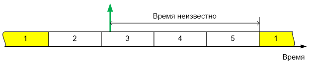
How much time has passed from the arrival of the impulse to the activation of the task producing the survey is unknown. As you can see, here too, the implementation of any reasonable data processing is possible only by interrupts. The impulse came, the time of his arrival was remembered, and the processing task can already use this time anytime.
From the foregoing it follows that
When working with the MAKS RTOS, interruptions are allowed to be processed in two ways - “convenient” and “fast”. Consider first the one that is considered the main option ("convenient").
As part of the OS, a standard task is developed, but it should be inherited not from Task , but from TaskIrq . This task is given a high priority, as it will have to force out all other tasks as soon as an interrupt occurs. The TaskIrq class contains the virtual function IrqHandler (), which should be blocked by placing all actions related to interrupt processing there.
During initialization, the interrupt should be resolved through the programming of the interrupt controller (I myself get scared how many times the word "interrupt" was said in the last two paragraphs, but alas, without this in any way). When setting the planning task, since it is inherited from a particular class, the number of the interrupt request that it processes should be specified as a parameter.
Ideologically, the challenge for this task can be represented as follows:
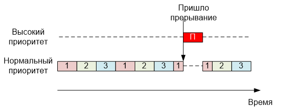
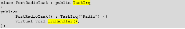
That is why its priority must be high - it is no different from other tasks, therefore, it must oust them, and this is done with the help of priority. Now consider a practical example. Here is a typical task - the handler of the radio module connected to the serial port. As you can see, it is actually inherited from TaskIrq, and the IrqHandler () function is really overridden in it.
This is how this task is added:
NVIC configuration for the radio module example will be moved out of this section. In my opinion, in this example, it is not very illustrative. Purely for illustration, let us show how NVIC is configured for a specific processor in another example (the option with a priority change was specifically chosen, although you can not change the priority).
So. The task is described, its TaskIrq function is overlapped, the task is added to the scheduler, what next? And then - the care of the OS. When an interrupt occurs, the internal interrupt handler will call the scheduler itself. That - activates the task. Here it is important that the task has a high priority , so that it is guaranteed to supplant other tasks. Well, after some time (required to switch tasks), the function IrqHandler () will get control. What should be placed in the body of this function are the problems of the application programmer (in the next part of the document, typical solutions will be described for cases of work through low-level drivers).
Standard solutions:
A simple example of an interrupt handler:
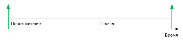
All possible problems from using the main interrupt handling mechanism are related to one: in order to wake up the task handler, the task context must be switched. It takes time. During practical work in a system with two tasks, we saw on the oscillogram that the switching took place in 4.7 microseconds. In general, the time depends on the build options, on the number of tasks, on other conditions. Let's take as a basis for further estimations a rather real and rather round value of 10 microseconds.
Let's look at a few typical scenarios of the equipment serviced by the microcontroller. Let's start with the simple. A CNC machine receiving G-CODE commands via a serial port at a speed of 250 kilobits. As already mentioned, the serial port bytes is 10 bits (8 data bits, plus the start and stop bits). Total, the frequency of arrival of bytes is 25 kHz. One byte in 40 microseconds. And the context switch takes 10 microseconds.
A quarter of the microcontroller's working time (a powerful 32-bit microcontroller) will only go to the context switch, since the G-Code lines go one after another, quite a dense stream. Is it acceptable? More likely no than yes.
Further, work with a stepper motor, which requires 200 steps per millimeter on a 3D printer that prints at a speed of 150 mm / s, requires work at a frequency of 30 KHz. This is even more than a quarter.
G-Code is adopted by the same controller that controls the stepper motors. In total, more than half of the CPU time is required for entering an interrupt.
Of course, this option is unacceptable .
But in other way. Take the same serial port, at the same speed, but connect to it the radio module from which 32-byte packets come 4 times per second. Thus, the load on the processor will increase in areas of 1200 microseconds long, and in a second such peak load periods will occur within 4800 microseconds. This is 4.8% of the time. Acceptable? More often than not. That is, we consider that this option is acceptable for processing in the standard way.
In the same way, it is possible to estimate that the already mentioned mechanism for determining the rotational speed of an engine from feedback signals will be unacceptable - the timer readings should be taken as close as possible to the moment of arrival of the signal. And the reading from the humidity sensor is quite acceptable. At the same time, data processing from the serial port at a speed of 921 kilobits per second will take 100% of the time to switch tasks, therefore it is unacceptable ... Well, and so on. The game "acceptable-unacceptable" can be played for a long time. Let's formulate the general principles.
If interrupts come rarely - the option is acceptable.
If interrupts come so often that a context switch takes 100 or more percent of the time, the option is unacceptable.
If a high percentage of time goes to the context switch, but this will happen quite rarely and in short enough packets - the option is acceptable.
If switching with high frequency will be permanent - the option is unacceptable.
What kind of replacement can I offer? Of course, direct interrupt handling.
You may ask: “Why not offer direct interrupt handling in all cases?”. I asked the exact same question for the developers of the MAX RTOS. Alas, their answer was categorical: there are reasons why standard processing is still more convenient.
Let's start with the simple. Interrupt Handler Names Even within the ARM families, they are different. Here are the most striking differences between the STM32 and Milandr families.
When migrating, they will need to be rewritten. Under the basic mechanism, the names of the handlers are the concern of the OS. They are hidden from the application programmer (it’s a pity that the names of the vectors are still not hidden, but you can’t do without it).
Further, when using the standard handler, the usual task is called. A real interrupt handler is hidden from the eyes of the application programmer. It merely awakens the task handler and tells the scheduler to switch context. Everything else is a common task. But with interruptions - everything is different there. If you look at the description of any OS (at least in real time, even though Windows), then it will be seen that many mechanisms do not work in the interrupt handler. A quick look at the mechanisms of the MAKS RTOS.
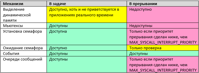
Let's see why a couple of records, it would seem, could be yellow (after all, under certain conditions, the mechanism is available), but it is marked in red. When implementing these mechanisms, it is required to exclude the possibility of re-entering the function. To do this, it contains a critical section, which, as we remember, blocks all interrupts whose priority is lower than MAX_SYSCALL_INTERRUPT_PRIORITY. Actually, that says it all. Interruptions are temporarily prohibited. That is, we do not benefit from direct interrupt handling. On the other hand, we are losing all the facilities available in the main interrupt handling mechanism. In general, in situations for which they abandon the main interrupt handling mechanism in favor of direct, semaphores cannot be set and message queues cannot be used. Therefore, in the table they are marked in red.
With direct interrupt processing, the reaction rate is determined only by the capabilities of the microcontroller. The list of interrupt handlers is conveniently taken from the startupXXXX.s file found in each project. In the demo application PinListAndTimerDemo, interrupt from timer 2 is processed, let's see how to quickly find the name of its handler.
 0
0
Knowing the name of the handler, it is very easy to make it using the following rules:
Thus, in the already mentioned example, the interrupt handler from timer 2 in the start code is named like this:
And the processing function, respectively,
It is important to remember that the handler of such an interrupt should be executed as quickly as possible. While the program is in the handler, all other tasks are not working, and interrupts with lower priority are blocked.
The interrupt handler must quickly accept the data, put it in for further processing and immediately stop its work. No complicated calculations, no other extra work in the interrupt handler should be located.
A convenient mechanism for associating interrupts with the main tasks is a ring buffer. An interrupt places received data into it as it arrives, and a task removes and uses it without worrying about processing speed.
The mcucpp library of Konstantin Chizhov, used as an auxiliary, already contains an implementation of ring buffers. A lot of the library itself will be discussed in the next part of the document, but for now let's consider the ring_buffer.h file.
The RingBuffer class uses the new operator to add each element in its work, so it cannot be used in real-time applications (and, moreover, in interrupts). But the same header file contains the class RingBufferPO2 - a ring buffer whose size is a multiple of a power of two. This class not only works with a pre-provisioned buffer, but is still so thread-safe for the “one writer, one reader” scheme, as far as the microcontroller command system allows (dangerous counters are recorded through the atomic access class, and security is determined by that class).
The class is defined as follows:
template <size_t SIZE, class T, class Atomic = VoidAtomic>
class RingBufferPO2
SIZE - the number of elements. Must be a multiple of the power of two, otherwise, the compiler will generate an error.
T is the type of stored data. Both scalars and structures are allowed.
Atomic - a class to ensure atomicity of operations (if not specified, atomicity is not provided).
Example declaration for the byte buffer received from the COM port (64 characters):
if the result is false, then the data was not placed because the buffer is full.
Usually, a function is used to retrieve data, which simultaneously pushes them out of the queue. For the case of scalar values, this is justified, but for the case of structures — an extra copy operation is performed — the data is copied to the new location, since they will be deleted from the old one. Most likely, to prevent copying, the author of the mcucpp library went a little different way. Data from the queue is not pushed, but read (it turns out a link to them). To delete data, use a separate function.
The main function of reading data can be called the following:
const T & front () const
T & back ()
As you can see, it returns a link to the data, that is, does not perform copying.
You can get a link to the very last item in the queue:
const T & back () const
T & front ()
You can even work with the queue by index:
const T & operator [] (size_type i) const
T & operator [] (size_type i)
Well, and when the need is no longer in the element, it should be removed from the queue using the function:
bool pop_front ()
If the queue is empty, the function will return false.
There are also auxiliary functions to check the queue for overcrowding and emptiness:
bool full () const
bool empty () const
You can find out how many specific items are currently in the queue:
size_type size () const
Finally, you can find out the capacity of the queue (although it is equal to the constant and is set at the program development stage, but for compatibility with dynamic buffers, these functions may be useful):
size_type max_size ()
size_type capacity ()
Let's check how bad the approach of calling two functions instead of one is. To get good reper, let's frame a code fragment with clearly defined calls (we cross out the corresponding lines).

The corresponding assembly code looks like this:
As you can see, the optimizer did not make function calls, but placed everything linearly. And the quality of the code is such that if there is one or two functions, there will be no difference. Nor will there be copying if structures are used.
Actually, the example is simple. Consider it on the example of buffering data coming from the COM port. In the third part of the document we will try to consider working with the COM port and its interruptions in more detail. We declare a buffer for 64 elements (I intuitively decided that such a buffer would not overflow if lines with an average length of 30 characters were processed).
In the interrupt handler, put the data in the buffer:
And in one of the tasks, among other things, we perform some actions, for example, such:
without fear of data being overwritten (of course, the queue size should be sufficient so that it does not overflow). Well, and we make certain actions with the received ch character. If the queue is empty, entry into the specified loop simply will not occur.
In order not to confuse you, let's start with a simple phrase: everything that is necessary to start working with interrupts has already been described. Everything else is already aerobatics. Probably the most correct thing is to first master the two extremes (slowly and conveniently, and also quickly and not very conveniently), and then return to reading this part of the section.
There is a mixed way to handle interrupts. First, the handler is rewritten, critical actions are performed at the beginning, and then the normal high-priority task is activated from it. In particular, for the case of frequency measurement - in this handler, the actual timer value can be obtained at the moment of arrival of the interrupt from the leg, then the timer is started for the next measurement, after which the problem of processing the value obtained from the timer is delegated to the normal task. Well, any other things. If the instant response is important, and the fact that the context switch takes time is not critical, then you can use this method.
So, we created a task spawned from TaskIrq, we created our own interrupt handler, in it we performed time-critical actions ... What next?
And then you should call the function MaksIrqHandler () . This function initiates context switching and control transfer to the function associated with the interrupt.
And finally, consider a mechanism that does not relate directly to interrupts, but is associated with them. This mechanism simply provides the programmer with additional, expressive information, without being mandatory.
When creating a task, the heir from TaskIRQ can be assigned an actually non-existent interrupt number. It must be greater than the FIRST_VIRT_IRQ value (for ARM, this value is 0x100, but for other architectures it may be different).
Such a task is not associated with any real interruption and will never be automatically activated by the kernel. But a programmer can always call a function:
void ProceedIrq (int irq_num);
after which the task will be activated according to all principles of the activation of the task associated with the interruption. What for? Variants are possible the most fantastic. For example, you can call several different handler tasks from one physical interrupt handler, if several devices are “hanging” on one vector (no matter how wide the range of IRQ lines is, and even on this, the controller developers manage to combine calls). In general, as one of the OS developers explained: “The mechanism went for nothing, why not use it?”. The ProceedIrq ( ) function is in any case necessary for the internal needs of the system.
At this point, the consideration of the core can be considered rough. Drivers are ahead, but about them - in the second volume of the manual.
Previous articles:
Part 1. General information
Part 2. Core MAX MAX
Part 3. The structure of the simplest program
Part 4. Useful theory
Part 5. The first application
Part 6. Thread synchronization tools
Part 7. Means of data exchange between tasks
Part 8. Work with interruptions (this article)
Why interruptions are vital
Computer science teachers love to talk about the fact that there is work on the survey, as well as on interruption, after which they usually give a small example of interrupt handling and forget about the topic. Further, with real programming, you have to comprehend the basics of this business not with your own skin.
')
When programming in single-tasking systems, it is often possible to "get out" by working with equipment according to the survey. In multitasking systems, it becomes more difficult.
Consider the simplest example. Let there be a reception from a serial port with a terribly low speed of 9600 AML. Real speeds have long been in the region of 250 KBDO, but in order to avoid the desire to simply slow down to solve a problem, let's consider the very slow option.
In the serial port, one byte is at my favorite port setting of 10 bits (8 data bits, as well as start and stop). Total, comes 960 bytes per second. Round up to 1000. This is 1 byte per millisecond. Place events on the time axis.
If the typical controller does not have time to process the next byte before the next one arrives, it will be overwritten by the new value coming from the line. Consider the essence of this on the diagram from the description of the controller STM32.
By default, tasks are switched 1 time in 1 millisecond. We will place on the time axis a case of sequential switching of five tasks.
Let the COM port be queried in task 1. Let's combine two pictures ...
As you can see, 4 bytes from the serial port will come when the task waiting for them is inactive. There are controllers with a large hardware queue. For example, ESP8266 can accept 128 bytes in a hardware buffer. Such controllers consider the situation at all - task 1 will receive the data accumulated by the equipment. But, for example, all STM32 input buffer can take no more than one byte. And for them, working with a serial port in a multitasking environment, according to the death survey, is similar even at such “funny” speeds as 9600 bits per second.
The correct decision will be to add the bytes to the buffer memory so that the processing task takes everything that has been accumulated in bulk. As an option, perform some kind of preprocessing (for example, initial analysis of packets, if this is possible without any special delays) and transfer the already preprocessed parameters to the processing task.
Of course, the example of a serial port was chosen as the one closest to most readers. In fact, there are many more cases where polling is poorly acceptable even in a single-task environment and impossible in a multi-tasking environment. The first thing that comes to mind is maintaining engine speed. The real case is that the engine rotates at a speed of up to 5 thousand revolutions per minute, from it comes two feedback pulses per revolution.
One of the typical algorithms for measuring the rotational speed, requires measuring the period of the following pulses using a timer. That is, you need to take a timer reading at the time of arrival, and then restart the timer for a new measurement. If from the moment of arrival of the pulse to the moment of taking the readings random time passes, the measurement accuracy will drop significantly. Most often - not just significantly, but unacceptably fall.
Let us estimate our situation - 10,000 feedback pulses per minute. Divide by 60 - we get 167 Hz. 1 pulse in 5 milliseconds, which should be processed as close as possible to the moment of its occurrence, in order not to lose measurement accuracy. The arrival time of the impulse cannot be predicted - the engine rotates the way it likes. With five tasks, the time of possible waiting for the transfer of control to the tracking task is more than half of the pulse repetition period. For example, this is the situation:
How much time has passed from the arrival of the impulse to the activation of the task producing the survey is unknown. As you can see, here too, the implementation of any reasonable data processing is possible only by interrupts. The impulse came, the time of his arrival was remembered, and the processing task can already use this time anytime.
From the foregoing it follows that
Interrupts in a multitasking environment are not only powerful, but often the only possible mechanism for working with hardware.
Main interrupt handling mechanism in RTOS MAX
When working with the MAKS RTOS, interruptions are allowed to be processed in two ways - “convenient” and “fast”. Consider first the one that is considered the main option ("convenient").
As part of the OS, a standard task is developed, but it should be inherited not from Task , but from TaskIrq . This task is given a high priority, as it will have to force out all other tasks as soon as an interrupt occurs. The TaskIrq class contains the virtual function IrqHandler (), which should be blocked by placing all actions related to interrupt processing there.
During initialization, the interrupt should be resolved through the programming of the interrupt controller (I myself get scared how many times the word "interrupt" was said in the last two paragraphs, but alas, without this in any way). When setting the planning task, since it is inherited from a particular class, the number of the interrupt request that it processes should be specified as a parameter.
Ideologically, the challenge for this task can be represented as follows:
That is why its priority must be high - it is no different from other tasks, therefore, it must oust them, and this is done with the help of priority. Now consider a practical example. Here is a typical task - the handler of the radio module connected to the serial port. As you can see, it is actually inherited from TaskIrq, and the IrqHandler () function is really overridden in it.
Text
class PortRadioTask : public TaskIrq { public: PortRadioTask() : TaskIrq("Radio") {} virtual void IrqHandler(); }; This is how this task is added:
const int Radio_IrqNumber = EXTI15_10_IRQn; ... result = TaskIrq::Add(radio_task = new PortRadioTask, Radio_IrqNumber, Task::PriorityRealtime); NVIC configuration for the radio module example will be moved out of this section. In my opinion, in this example, it is not very illustrative. Purely for illustration, let us show how NVIC is configured for a specific processor in another example (the option with a priority change was specifically chosen, although you can not change the priority).
NVIC_EnableIRQ(EXTI9_5_IRQn); NVIC_SetPriority(EXTI9_5_IRQn,1); So. The task is described, its TaskIrq function is overlapped, the task is added to the scheduler, what next? And then - the care of the OS. When an interrupt occurs, the internal interrupt handler will call the scheduler itself. That - activates the task. Here it is important that the task has a high priority , so that it is guaranteed to supplant other tasks. Well, after some time (required to switch tasks), the function IrqHandler () will get control. What should be placed in the body of this function are the problems of the application programmer (in the next part of the document, typical solutions will be described for cases of work through low-level drivers).
Standard solutions:
- you can accept data, preprocess it, put in a message queue for a task with normal priority,
- or you can coax the semaphore for a task with normal priority
A simple example of an interrupt handler:
Semaphore s_sema_radio_irq(0, 1); // void PortRadioTask::IrqHandler() { s_sema_radio_irq.Signal(); } Possible problems when using the main mechanism
All possible problems from using the main interrupt handling mechanism are related to one: in order to wake up the task handler, the task context must be switched. It takes time. During practical work in a system with two tasks, we saw on the oscillogram that the switching took place in 4.7 microseconds. In general, the time depends on the build options, on the number of tasks, on other conditions. Let's take as a basis for further estimations a rather real and rather round value of 10 microseconds.
Let's look at a few typical scenarios of the equipment serviced by the microcontroller. Let's start with the simple. A CNC machine receiving G-CODE commands via a serial port at a speed of 250 kilobits. As already mentioned, the serial port bytes is 10 bits (8 data bits, plus the start and stop bits). Total, the frequency of arrival of bytes is 25 kHz. One byte in 40 microseconds. And the context switch takes 10 microseconds.
A quarter of the microcontroller's working time (a powerful 32-bit microcontroller) will only go to the context switch, since the G-Code lines go one after another, quite a dense stream. Is it acceptable? More likely no than yes.
Further, work with a stepper motor, which requires 200 steps per millimeter on a 3D printer that prints at a speed of 150 mm / s, requires work at a frequency of 30 KHz. This is even more than a quarter.
G-Code is adopted by the same controller that controls the stepper motors. In total, more than half of the CPU time is required for entering an interrupt.
Of course, this option is unacceptable .
But in other way. Take the same serial port, at the same speed, but connect to it the radio module from which 32-byte packets come 4 times per second. Thus, the load on the processor will increase in areas of 1200 microseconds long, and in a second such peak load periods will occur within 4800 microseconds. This is 4.8% of the time. Acceptable? More often than not. That is, we consider that this option is acceptable for processing in the standard way.
In the same way, it is possible to estimate that the already mentioned mechanism for determining the rotational speed of an engine from feedback signals will be unacceptable - the timer readings should be taken as close as possible to the moment of arrival of the signal. And the reading from the humidity sensor is quite acceptable. At the same time, data processing from the serial port at a speed of 921 kilobits per second will take 100% of the time to switch tasks, therefore it is unacceptable ... Well, and so on. The game "acceptable-unacceptable" can be played for a long time. Let's formulate the general principles.
If interrupts come rarely - the option is acceptable.
If interrupts come so often that a context switch takes 100 or more percent of the time, the option is unacceptable.
If a high percentage of time goes to the context switch, but this will happen quite rarely and in short enough packets - the option is acceptable.
If switching with high frequency will be permanent - the option is unacceptable.
What kind of replacement can I offer? Of course, direct interrupt handling.
Why you should not abandon the main mechanism
You may ask: “Why not offer direct interrupt handling in all cases?”. I asked the exact same question for the developers of the MAX RTOS. Alas, their answer was categorical: there are reasons why standard processing is still more convenient.
Let's start with the simple. Interrupt Handler Names Even within the ARM families, they are different. Here are the most striking differences between the STM32 and Milandr families.
| STM32 | "Milander" |
| USART1_IRQHandler | UART1_IRQHandler |
| TIM1_UP_TIM10_IRQHandler | Timer1_IRQHandler |
| TIM2_IRQHandler | Timer2_IRQHandler |
When migrating, they will need to be rewritten. Under the basic mechanism, the names of the handlers are the concern of the OS. They are hidden from the application programmer (it’s a pity that the names of the vectors are still not hidden, but you can’t do without it).
Further, when using the standard handler, the usual task is called. A real interrupt handler is hidden from the eyes of the application programmer. It merely awakens the task handler and tells the scheduler to switch context. Everything else is a common task. But with interruptions - everything is different there. If you look at the description of any OS (at least in real time, even though Windows), then it will be seen that many mechanisms do not work in the interrupt handler. A quick look at the mechanisms of the MAKS RTOS.
Let's see why a couple of records, it would seem, could be yellow (after all, under certain conditions, the mechanism is available), but it is marked in red. When implementing these mechanisms, it is required to exclude the possibility of re-entering the function. To do this, it contains a critical section, which, as we remember, blocks all interrupts whose priority is lower than MAX_SYSCALL_INTERRUPT_PRIORITY. Actually, that says it all. Interruptions are temporarily prohibited. That is, we do not benefit from direct interrupt handling. On the other hand, we are losing all the facilities available in the main interrupt handling mechanism. In general, in situations for which they abandon the main interrupt handling mechanism in favor of direct, semaphores cannot be set and message queues cannot be used. Therefore, in the table they are marked in red.
So, if you have the opportunity to use all the features of the OS, then it is better and easier to use them, and go to the direct processing of interrupts only if there is an urgent need.
Direct Interrupt Handling
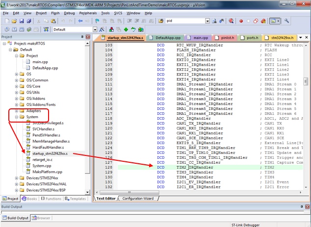
With direct interrupt processing, the reaction rate is determined only by the capabilities of the microcontroller. The list of interrupt handlers is conveniently taken from the startupXXXX.s file found in each project. In the demo application PinListAndTimerDemo, interrupt from timer 2 is processed, let's see how to quickly find the name of its handler.
0Knowing the name of the handler, it is very easy to make it using the following rules:
- If it is located in the cpp file (C ++ code), you should definitely add the extern “C” prefix. Without this, the function name will be formed according to the rules of C ++ and the system will not understand that we are replacing the interrupt handler.
- The return type is void.
- Arguments are not.
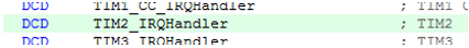
Thus, in the already mentioned example, the interrupt handler from timer 2 in the start code is named like this:
And the processing function, respectively,
extern "C" void TIM2_IRQHandler (void) { ... It is important to remember that the handler of such an interrupt should be executed as quickly as possible. While the program is in the handler, all other tasks are not working, and interrupts with lower priority are blocked.
The interrupt handler must quickly accept the data, put it in for further processing and immediately stop its work. No complicated calculations, no other extra work in the interrupt handler should be located.
A convenient mechanism for associating interrupts with the main tasks is a ring buffer. An interrupt places received data into it as it arrives, and a task removes and uses it without worrying about processing speed.
Mcucpp ring buffer
The mcucpp library of Konstantin Chizhov, used as an auxiliary, already contains an implementation of ring buffers. A lot of the library itself will be discussed in the next part of the document, but for now let's consider the ring_buffer.h file.
The RingBuffer class uses the new operator to add each element in its work, so it cannot be used in real-time applications (and, moreover, in interrupts). But the same header file contains the class RingBufferPO2 - a ring buffer whose size is a multiple of a power of two. This class not only works with a pre-provisioned buffer, but is still so thread-safe for the “one writer, one reader” scheme, as far as the microcontroller command system allows (dangerous counters are recorded through the atomic access class, and security is determined by that class).
The class is defined as follows:
template <size_t SIZE, class T, class Atomic = VoidAtomic>
class RingBufferPO2
SIZE - the number of elements. Must be a multiple of the power of two, otherwise, the compiler will generate an error.
T is the type of stored data. Both scalars and structures are allowed.
Atomic - a class to ensure atomicity of operations (if not specified, atomicity is not provided).
The buffer for storing data is a member variable of the class. Therefore, the class object should be placed in the pool in which there is enough free space (stack, heap, global memory, a specially defined memory pool, etc.)
Example declaration for the byte buffer received from the COM port (64 characters):
Mcucpp::Containers::RingBufferPO2<64, uint8_t, Mcucpp::Atomic> bufFromUart; , <b>bool push_back(const T& value)</b> if the result is false, then the data was not placed because the buffer is full.
Usually, a function is used to retrieve data, which simultaneously pushes them out of the queue. For the case of scalar values, this is justified, but for the case of structures — an extra copy operation is performed — the data is copied to the new location, since they will be deleted from the old one. Most likely, to prevent copying, the author of the mcucpp library went a little different way. Data from the queue is not pushed, but read (it turns out a link to them). To delete data, use a separate function.
The main function of reading data can be called the following:
const T & front () const
T & back ()
As you can see, it returns a link to the data, that is, does not perform copying.
You can get a link to the very last item in the queue:
const T & back () const
T & front ()
You can even work with the queue by index:
const T & operator [] (size_type i) const
T & operator [] (size_type i)
Well, and when the need is no longer in the element, it should be removed from the queue using the function:
bool pop_front ()
If the queue is empty, the function will return false.
There are also auxiliary functions to check the queue for overcrowding and emptiness:
bool full () const
bool empty () const
You can find out how many specific items are currently in the queue:
size_type size () const
Finally, you can find out the capacity of the queue (although it is equal to the constant and is set at the program development stage, but for compatibility with dynamic buffers, these functions may be useful):
size_type max_size ()
size_type capacity ()
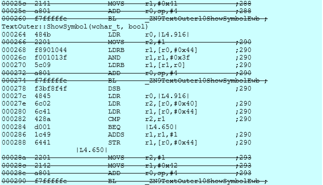
Let's check how bad the approach of calling two functions instead of one is. To get good reper, let's frame a code fragment with clearly defined calls (we cross out the corresponding lines).
Text
txtOuter.ShowSymbol('A'); txtOuter.ShowSymbol(bufFromUart.front()); bufFromUart.pop_front(); txtOuter.ShowSymbol('B'); The corresponding assembly code looks like this:
Text
00025c 2141 MOVS r1,#0x41 ;288
00025e a801 ADD r0,sp,#4 ;288
000260 f7fffffe BL _ZN9TextOuter10ShowSymbolEwb ; TextOuter::ShowSymbol(wchar_t, bool)
000264 484b LDR r0,|L4.916|
000266 2201 MOVS r2,#1 ;290
000268 f8901044 LDRB r1,[r0,#0x44] ;290
00026c f001013f AND r1,r1,#0x3f ;290
000270 5c09 LDRB r1,[r1,r0] ;290
000272 a801 ADD r0,sp,#4 ;290
000274 f7fffffe BL _ZN9TextOuter10ShowSymbolEwb ;
000278 f3bf8f4f DSB ;290
00027c 4845 LDR r0,|L4.916|
00027e 6c02 LDR r2,[r0,#0x40] ;290
000280 6c41 LDR r1,[r0,#0x44] ;290
000282 428a CMP r2,r1 ;290
000284 d001 BEQ |L4.650|
000286 1c49 ADDS r1,r1,#1 ;290
000288 6441 STR r1,[r0,#0x44] ;290
|L4.650|
00028a 2201 MOVS r2,#1 ;293
00028c 2142 MOVS r1,#0x42 ;293
00028e a801 ADD r0,sp,#4 ;293
000290 f7fffffe BL _ZN9TextOuter10ShowSymbolEwb ;
As you can see, the optimizer did not make function calls, but placed everything linearly. And the quality of the code is such that if there is one or two functions, there will be no difference. Nor will there be copying if structures are used.
Ring Buffer Example
Actually, the example is simple. Consider it on the example of buffering data coming from the COM port. In the third part of the document we will try to consider working with the COM port and its interruptions in more detail. We declare a buffer for 64 elements (I intuitively decided that such a buffer would not overflow if lines with an average length of 30 characters were processed).
#include <ring_buffer.h> #include <atomic.h> ... Mcucpp::Containers::RingBufferPO2<64, uint8_t, Mcucpp::Atomic> bufFromUart; In the interrupt handler, put the data in the buffer:
bufFromUart.push_back (Buf[i]); And in one of the tasks, among other things, we perform some actions, for example, such:
while (!bufFromUart.empty()) { char ch = bufFromUart.front(); bufFromUart.pop_front(); ... without fear of data being overwritten (of course, the queue size should be sufficient so that it does not overflow). Well, and we make certain actions with the received ch character. If the queue is empty, entry into the specified loop simply will not occur.
Mixed interrupt handling
In order not to confuse you, let's start with a simple phrase: everything that is necessary to start working with interrupts has already been described. Everything else is already aerobatics. Probably the most correct thing is to first master the two extremes (slowly and conveniently, and also quickly and not very conveniently), and then return to reading this part of the section.
There is a mixed way to handle interrupts. First, the handler is rewritten, critical actions are performed at the beginning, and then the normal high-priority task is activated from it. In particular, for the case of frequency measurement - in this handler, the actual timer value can be obtained at the moment of arrival of the interrupt from the leg, then the timer is started for the next measurement, after which the problem of processing the value obtained from the timer is delegated to the normal task. Well, any other things. If the instant response is important, and the fact that the context switch takes time is not critical, then you can use this method.
So, we created a task spawned from TaskIrq, we created our own interrupt handler, in it we performed time-critical actions ... What next?
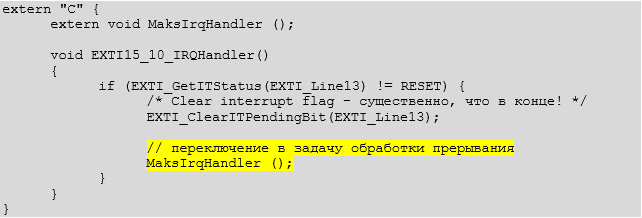
And then you should call the function MaksIrqHandler () . This function initiates context switching and control transfer to the function associated with the interrupt.
Text
extern "C" { extern void MaksIrqHandler (); void EXTI15_10_IRQHandler() { if (EXTI_GetITStatus(EXTI_Line13) != RESET) { /* Clear interrupt flag - , ! */ EXTI_ClearITPendingBit(EXTI_Line13); // MaksIrqHandler (); } } } Virtual interrupts
And finally, consider a mechanism that does not relate directly to interrupts, but is associated with them. This mechanism simply provides the programmer with additional, expressive information, without being mandatory.
When creating a task, the heir from TaskIRQ can be assigned an actually non-existent interrupt number. It must be greater than the FIRST_VIRT_IRQ value (for ARM, this value is 0x100, but for other architectures it may be different).
Such a task is not associated with any real interruption and will never be automatically activated by the kernel. But a programmer can always call a function:
void ProceedIrq (int irq_num);
after which the task will be activated according to all principles of the activation of the task associated with the interruption. What for? Variants are possible the most fantastic. For example, you can call several different handler tasks from one physical interrupt handler, if several devices are “hanging” on one vector (no matter how wide the range of IRQ lines is, and even on this, the controller developers manage to combine calls). In general, as one of the OS developers explained: “The mechanism went for nothing, why not use it?”. The ProceedIrq ( ) function is in any case necessary for the internal needs of the system.
At this point, the consideration of the core can be considered rough. Drivers are ahead, but about them - in the second volume of the manual.
Source: https://habr.com/ru/post/340032/
All Articles