Comparing tick-to-trade delays with CEPappliance and Solarflare TCPDirect
In this article, we present the values of delays measured for two types of environments — a device based on the FPGA CEPappliance (“piece of hardware ”) and a computer with the Solarflare network board in TCPDirect mode, we describe how we obtained these measurements — we describe the measurement technique and its technical implementation. At the end of the article there is a link to GitHub with the obtained results and some sources.
It seems to us that our results may be of interest to high-frequency traders, algorithmic traders and all those who are not indifferent to data processing with low latency.
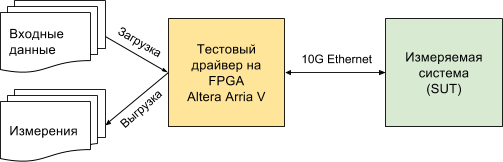
The scheme of the measuring stand looks like this:
')
SUT (System Under Test) is either a CEPappliance or a server with Solarflare (see below for characteristics of the systems under test).
CEPappliance and Solarflare have a common scope of application - high-frequency and algorithmic trading. Therefore, we took as a basis the scenario from this area, measuring the amount of delay from the moment the test driver sent the last byte of the packet with market data (tick) until it received the first byte of the packet with the application (trade) to the exchange (the MAC delay and PHY driver levels are the same for both test environments and subtracted from the resulting values below) - the so-called tick-to-trade delay. Measuring the time from the moment the driver sends the last byte, we eliminate the influence of the speed of data transmission / reception, which depends on the physical layer.
You can measure the delay using another method, such as the time from the moment the driver sends the first byte to the moment it receives the first byte from the system being measured. Such a delay will be longer and can be calculated on the basis of our measurements using the formula:
latency 1-1 = latency N-1 + 6.4 * int ((N + 7) / 8) ,
where latency N-1 is the delay we measured (from the moment the driver sent the last byte to the moment it received the first byte), N is the Ethernet frame length in bytes, int (x) is the conversion to the integer, dropping the fractional part of a real number.
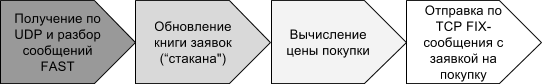
Here is the processing scheme, the execution time of which is the delay of interest:
What are the stages of testing?
Training:
Testing:
Processing test results:
The SUT is a server with an Asus P9X79 WS motherboard, an Intel Core i7-3930K CPU @ 3.20GHz processor and an SFN8522-R2 Flareon Ultra 8000 Series 10G Adapter, which supports TCPDirect.
For this booth, a C-program was written that receives UDP packets through the Solarflare TCPDirect API, parses them, builds the order book, generates and sends a purchase message using the FIX protocol.
Parsing a message, building a glass, forming a message with an application is coded “hard” without the support of any variations and checks in order to ensure minimum delay. The code is available on GitHub .
The SUT is the CEP appliance, or “piece of hardware,” as we call it, the DE5-Net board with an Altera Stratix V FPGA chip, inserted into the server's PCIe slot, through which it receives power and nothing else. Management and data exchange with the board is carried out via a 10G Ethernet connection.
We have already told that our firmware for the FPGA chip contains many different components, including everything necessary to implement the test script described here.
The script program for the CEP appliance is contained in two files. In one file , a data processing logic program, which we call a schema. In another file, the description of adapters through which the circuit (or the piece of hardware that executes it) interacts with the outside world. Just like that!
For CEPappliance, we implemented two versions of the scheme and made measurements for each version. In one version (CEP appliance ALU), the logic is implemented in the embedded high-level language (see lines 47–67 ). In the other (CEPappliance WIRE) - on Verilog (see lines 47-54 ).
Measured tick-to-trade delays in nanoseconds:
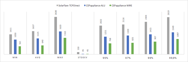
The miracle did not happen and the hardware implemented on the basis of FPGA turned out to be faster than the solution based on the server with Solarflare TCPDirect. The higher the percentile, the more noticeable the difference in speed. At the same time, the speed of the solution at the CEPappliance has a dispersion an order of magnitude lower.
The option for CEPappliance, when the data processing logic is implemented on Verilog, is 60-70% faster than implementing the same algorithm in the embedded CEPappliance language.
We have placed almost all of the source code that participated in the testing, open on GitHub in this repository .
Only the test driver code was left closed, since there is a hope to monetize it. After all, it allows you to very accurately measure the reaction rate of the system. And without this information to make high-quality HFT-solution is almost impossible.
It would be logical to find out whether the identified difference in the delays of various solutions is important, for example, when trading on the Moscow Stock Exchange. This will be in the next article. But looking ahead, let's say that even half a microsecond matters!
It seems to us that our results may be of interest to high-frequency traders, algorithmic traders and all those who are not indifferent to data processing with low latency.
Measurement technique: what and how we measured
The scheme of the measuring stand looks like this:
')
SUT (System Under Test) is either a CEPappliance or a server with Solarflare (see below for characteristics of the systems under test).
CEPappliance and Solarflare have a common scope of application - high-frequency and algorithmic trading. Therefore, we took as a basis the scenario from this area, measuring the amount of delay from the moment the test driver sent the last byte of the packet with market data (tick) until it received the first byte of the packet with the application (trade) to the exchange (the MAC delay and PHY driver levels are the same for both test environments and subtracted from the resulting values below) - the so-called tick-to-trade delay. Measuring the time from the moment the driver sends the last byte, we eliminate the influence of the speed of data transmission / reception, which depends on the physical layer.
You can measure the delay using another method, such as the time from the moment the driver sends the first byte to the moment it receives the first byte from the system being measured. Such a delay will be longer and can be calculated on the basis of our measurements using the formula:
latency 1-1 = latency N-1 + 6.4 * int ((N + 7) / 8) ,
where latency N-1 is the delay we measured (from the moment the driver sent the last byte to the moment it received the first byte), N is the Ethernet frame length in bytes, int (x) is the conversion to the integer, dropping the fractional part of a real number.
Here is the processing scheme, the execution time of which is the delay of interest:
What are the stages of testing?
Training:
- Input data - recorded dump of the order flow from the ATSTS system of the Moscow Exchange in the form of messages packed using the FAST protocol and transmitted via UDP
- Data is loaded into the memory of the test driver using the utility.
Testing:
- Test driver
- sends recorded UDP packets (loses a dump) with market data - information about buy or sell orders (orders) accepted by the exchange; The information includes the action with the order - adding a new order, changing or deleting a previously added order, the identifier of the traded financial instrument, the purchase / sale price, the number of lots, etc .;
- One package may contain information about one or several applications (after changes in the data packaging rules issued by the exchange in March 2017, we met packages with information on 128 applications!);
- remembers the sending time of a T1 packet.
- Test system
- accepts a package with information about applications;
- unpacks it according to the packing rules specified by the exchange ( X-OLR-CURR orders flow message from the Moscow Exchange currency market);
- updates its internal order book (“cups”), applying all the data from the received package;
- if the best (lowest) selling price in the book has changed, send a purchase request with this price using the FIX protocol.
- Test driver
- receives TCP packet with the application;
- captures the time of receipt T2;
- calculates the delay (T2 -T1) and remembers it.
- Testing is performed on a set of 90,000 packets with market data, and statistical values are calculated on the resulting set of delay values (average, variance, percentiles). Packages are sent strictly in turn. After sending a packet, we wait for a response, or the timeout expires (if the algorithm does not have to respond to this packet with market data). After that we send the following packet, etc.
Processing test results:
- The resulting average delay values are unloaded from the memory of the test driver.
- Each delay value is stored with the size of the input data packet for which it was measured.
Stand for Solarflare
The SUT is a server with an Asus P9X79 WS motherboard, an Intel Core i7-3930K CPU @ 3.20GHz processor and an SFN8522-R2 Flareon Ultra 8000 Series 10G Adapter, which supports TCPDirect.
For this booth, a C-program was written that receives UDP packets through the Solarflare TCPDirect API, parses them, builds the order book, generates and sends a purchase message using the FIX protocol.
Parsing a message, building a glass, forming a message with an application is coded “hard” without the support of any variations and checks in order to ensure minimum delay. The code is available on GitHub .
Stand for “hardware” CEPappliance
The SUT is the CEP appliance, or “piece of hardware,” as we call it, the DE5-Net board with an Altera Stratix V FPGA chip, inserted into the server's PCIe slot, through which it receives power and nothing else. Management and data exchange with the board is carried out via a 10G Ethernet connection.
We have already told that our firmware for the FPGA chip contains many different components, including everything necessary to implement the test script described here.
The script program for the CEP appliance is contained in two files. In one file , a data processing logic program, which we call a schema. In another file, the description of adapters through which the circuit (or the piece of hardware that executes it) interacts with the outside world. Just like that!
For CEPappliance, we implemented two versions of the scheme and made measurements for each version. In one version (CEP appliance ALU), the logic is implemented in the embedded high-level language (see lines 47–67 ). In the other (CEPappliance WIRE) - on Verilog (see lines 47-54 ).
results
Measured tick-to-trade delays in nanoseconds:
| SUT | min | avg | max | stddev | 95% | 97% | 99% | 99.9% |
|---|---|---|---|---|---|---|---|---|
| Solarflare TCPDirect | 1411 | 1637 | 2638 | 150 | 2022 | 2116 | 2303 | 2619 |
| CEPappliance ALU | 1050 | 1125 | 1620 | 45 | 1251 | 1320 | 1415 | 1549 |
| CEPappliance WIRE | 561 | 640 | 1163 | 45 | 768 | 825 | 907 | 1087 |
findings
The miracle did not happen and the hardware implemented on the basis of FPGA turned out to be faster than the solution based on the server with Solarflare TCPDirect. The higher the percentile, the more noticeable the difference in speed. At the same time, the speed of the solution at the CEPappliance has a dispersion an order of magnitude lower.
The option for CEPappliance, when the data processing logic is implemented on Verilog, is 60-70% faster than implementing the same algorithm in the embedded CEPappliance language.
Source
We have placed almost all of the source code that participated in the testing, open on GitHub in this repository .
Only the test driver code was left closed, since there is a hope to monetize it. After all, it allows you to very accurately measure the reaction rate of the system. And without this information to make high-quality HFT-solution is almost impossible.
What's next?
It would be logical to find out whether the identified difference in the delays of various solutions is important, for example, when trading on the Moscow Stock Exchange. This will be in the next article. But looking ahead, let's say that even half a microsecond matters!
Source: https://habr.com/ru/post/339702/
All Articles