The history of the clock synchronizer DCF77
Once I decided to please myself and bought a citizen watch. Among other things, these watches announced the ability to synchronize watches over the air. At the time of the order, I did not really imagine what it was, I thought that it would somehow do everything right. But it turned out that radio synchronization in Russia practically does not work. I decided to correct the situation. The first thing I found was an article about signal amplification. It was suggested to wind a large coil with a capacitor, put it on the window facing west and wait. Also in this article, the dcf77 protocol was mentioned, according to which the clock synchronizes time, and I realized that it is not very complicated. Although at the moment in electronics I was a complete zero, but it seemed to me that I could cope with the digital part, and somehow deal with the rest. And I decided to start a project to develop a clock synchronization device using the dcf77 protocol.
Here I will describe how I worked on this project, what problems I faced, being a novice in electronics, interesting solutions that I came across while working on a project, and I will try to justify them. This text may be of interest to programmers who decide to engage in electronics. Therefore, on the programming side, many things will be omitted.
The first thing I started is to collect information about the protocol, possible finished devices, and thought out the requirements for the device. I started thinking about the basic concept.
')
1. Synchronization must be performed within the room.
2. The synchronizer itself may have an error of 2s
3. The synchronizer should be for hours.
4. Must have a self-diagnostic system.
5. Must be battery powered. (I'm not sure I can make a device that can work safely on the network to others)
6. From the battery, the device should work for about a month.
7. Everything should be beautiful. Housing Screen. Buttons. Etc.
Then I began to collect material about the protocol and similar devices. Somewhere on the German resources were some ready-made devices . Found a description of the protocol on Wikipedia .
Since this all started.
What is dcf77? This is a protocol in which the date and time is transmitted by zeros and units of an amplitude modulated signal. At the beginning of each second, the amplitude is reduced to 15% by 0.1 or 0.2 s. If the length of the reduced signal is 0.1 s, then 0, if 0.2 s, then 1. What is clearly visible when blinking the LED. Read more here and here .
The first thing I did was implement the dcf77 protocol on a large computer in c ++. I did this quickly. It is clear that I tried to make flashing lights on arduino, therefore, it was not difficult to make flashing lights using dcf77 protocol on the LED. Photos or schemes of the very first versions I, unfortunately, did not survive. But the scheme was about the same as in the figure. Only without a generator and on the Arduino Uno.
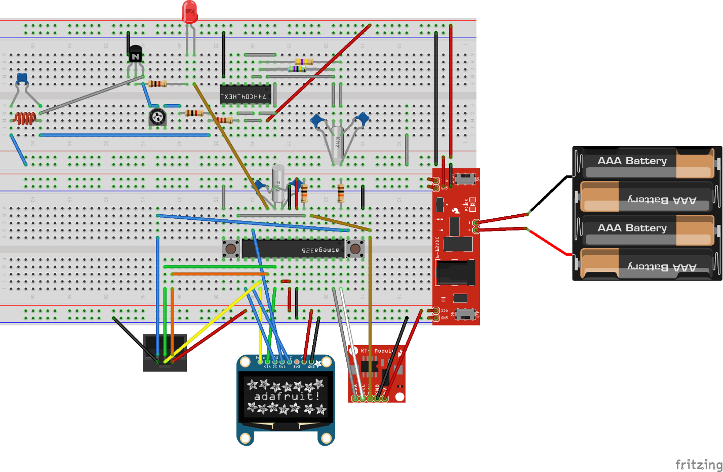
On the way to such a scheme encountered some difficulties.
The first thing I encountered was that classes in the Arduino ide in the ino file cannot be implemented. I had to rewrite everything to C. I did not immediately realize that it was possible to simply connect it from a separate file. This problem was resolved quickly.
Due to the fact that I started with the fact that the signal was visualized by the LED, the resistor was sequentially set to the LED at around 200 ohms (the picture is no longer the case). To make it shine brighter. This all led to the fact that the transistor was constantly ajar and the circuit did not work normally. At random, I guessed to put two diodes in series.
The transistor seems to be closing. But it somehow looked wildly, even for me, and I realized that I needed to study the theory. Ase know very important. At least how the transistor works in key mode. And here I encountered the following problem: few details and few tools. For example, to make an antenna, you need a wire and ferrite. From China to wait for them for a long time. Fortunately, the hex invertor was in the Arduino starter. But I did not find quartz at 77500 in Russia at all, and even in China, at ali, he was only in one place, a batch of 50 pieces. By this time, I already realized that even if I put together a generator, I would not even be able to understand whether it works or not. And I realized that I needed tools: I needed a frequency meter and / or an oscilloscope. This gave me a break in the work on the device. And I began to study electronics. Listened to a number of YouTube videos on electronics, for example, this . Related articles. Articles on antennas. Very worried that the antennas for this frequency should be about 700 meters long. But still decided to try to make a magnetic antenna in the receivers .
An antenna needs a circuit from a magnetic coil and a capacitor in resonance. Resonance must somehow be sought. This led to the transistor tester project. He also wanted to implement it in between. There was an inductance meter there, and I had a few Arduino mini (plz Arduino haters, don't react right away. Then I corrected a little). But I realized that I was not ready to do it myself, ordered DYI, looked at his scheme and found his source .
Also learned about some useful programs for the phone, it is EveryCircuit and ElectroDroid. ElectroDroid I at this moment used to calculate the resonance of the antenna. EveryCircuit allows you to simulate small schemes on the phone. Decided to document and scheme. Somewhere on the Internet I saw a beautiful picture on a breadboard. I realized that this is what Fritzing does, in addition, he can design the circuit and the board. Began to use fritzing.
It was already time that the first parcels from China began to arrive. Something had to urgently order in the "chip and dip". This is where the first idea came about how to synchronize time. It was decided to synchronize on the wifi module esp8266.
Stumbled upon a similar project . I decided to take the main ideas from it. The radio part is completely borrowed from it. It was impossible to use it without rework, because:
1. It is rated at 12 volts.
2. Based on microcontroller pic.
As the details arrived, I began to improve the device. After the quartz and the transistor tester arrived, it became possible to finally assemble the first version capable of transmitting time. Wound the coil on a ferrite rod - this is the antenna. Looked at her inductance. Picked up capacitors of 100 pf. All kind of collected. Should work. And does not work. And, of course, the problem cannot be diagnosed. The oscilloscope has not arrived yet. Even the multimer is the easiest. According to him, little can be understood. It is good that my father-in-law had instruments and an oscilloscope and a frequency meter. I went to him with my device. We looked at the frequency meter like the frequency is. We looked at the oscilloscope, too, like nothing. The sine is not clear, but still looks like. I went home to understand further. The problem is that how to understand it is not clear. By the clock you can understand only if they saw the signal or not. To understand the error is impossible. But nevertheless, it is clear that the problem is not in the radio part, but in the modulator. I tried to vary the parameters. Without going far from the description from Wikipedia. In the end, I decided to lengthen the pulses on in the frequency modulator. And at that moment the clock finally hooked the signal. And, after several attempts, AFTERMAN succeeded in performing the first synchronization. Then it was decided to do time synchronization on the device itself.
In the process of searching for problems, I also discovered that digitalwrite works inefficiently.
Redid everything so that it does not use. Then I met this in other sources. But for the first time I saw it here . This was the first retreat from the Arduino.
I really like the oled screens, so it was decided to use the ssd1306 screen. But the library from adafruit is terrible. She is very slow. Uses a lot of RAM. Found an alternative to u8glib . I really liked.
The first solution I tried was based on the esp8266 module and implied time synchronization via the Internet. But I did not like the fact that it is rather difficult to connect through this module. And at that moment it was not very stable. Therefore, it occurred to me to try time synchronization via GPS. The module for ardino was like that. The firmware for synchronization via GPS was easier, but there were problems that I encountered in the future.
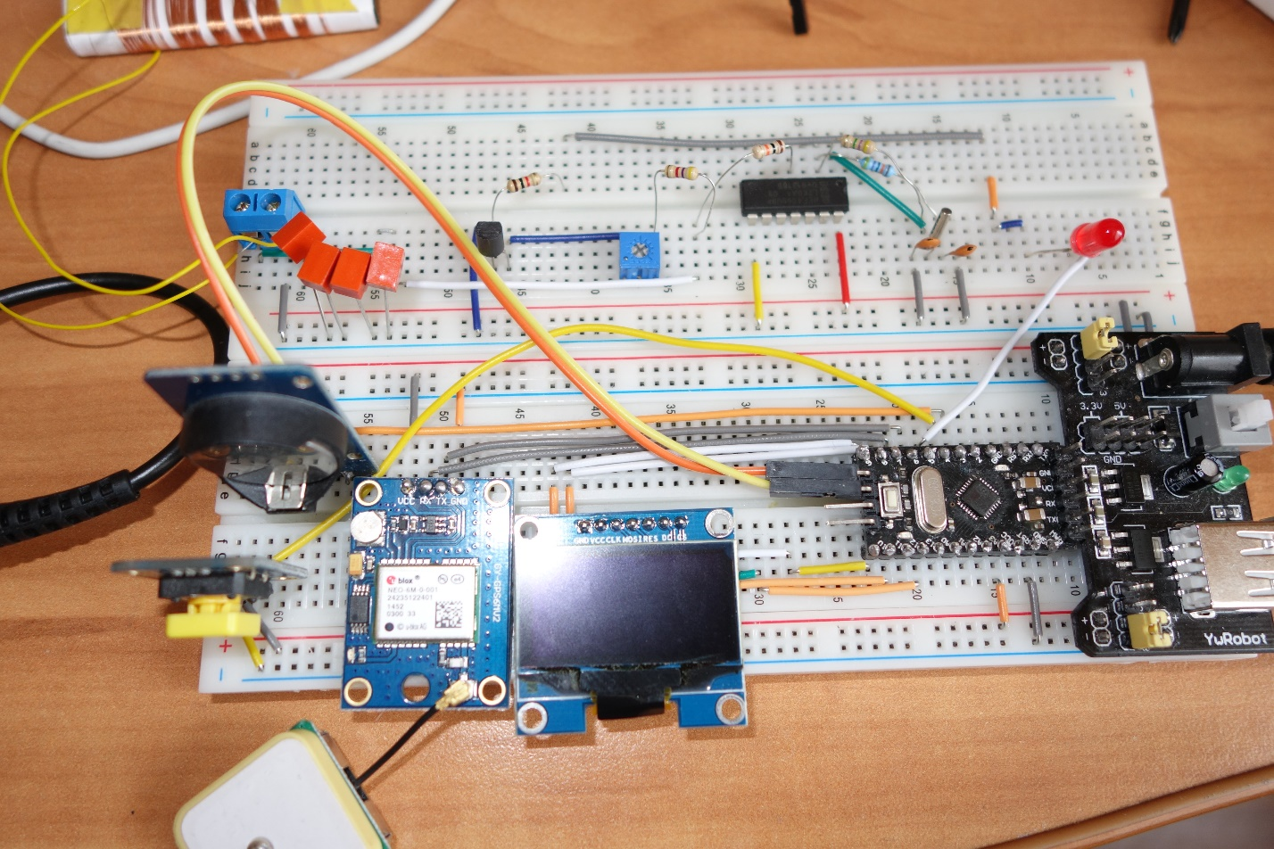
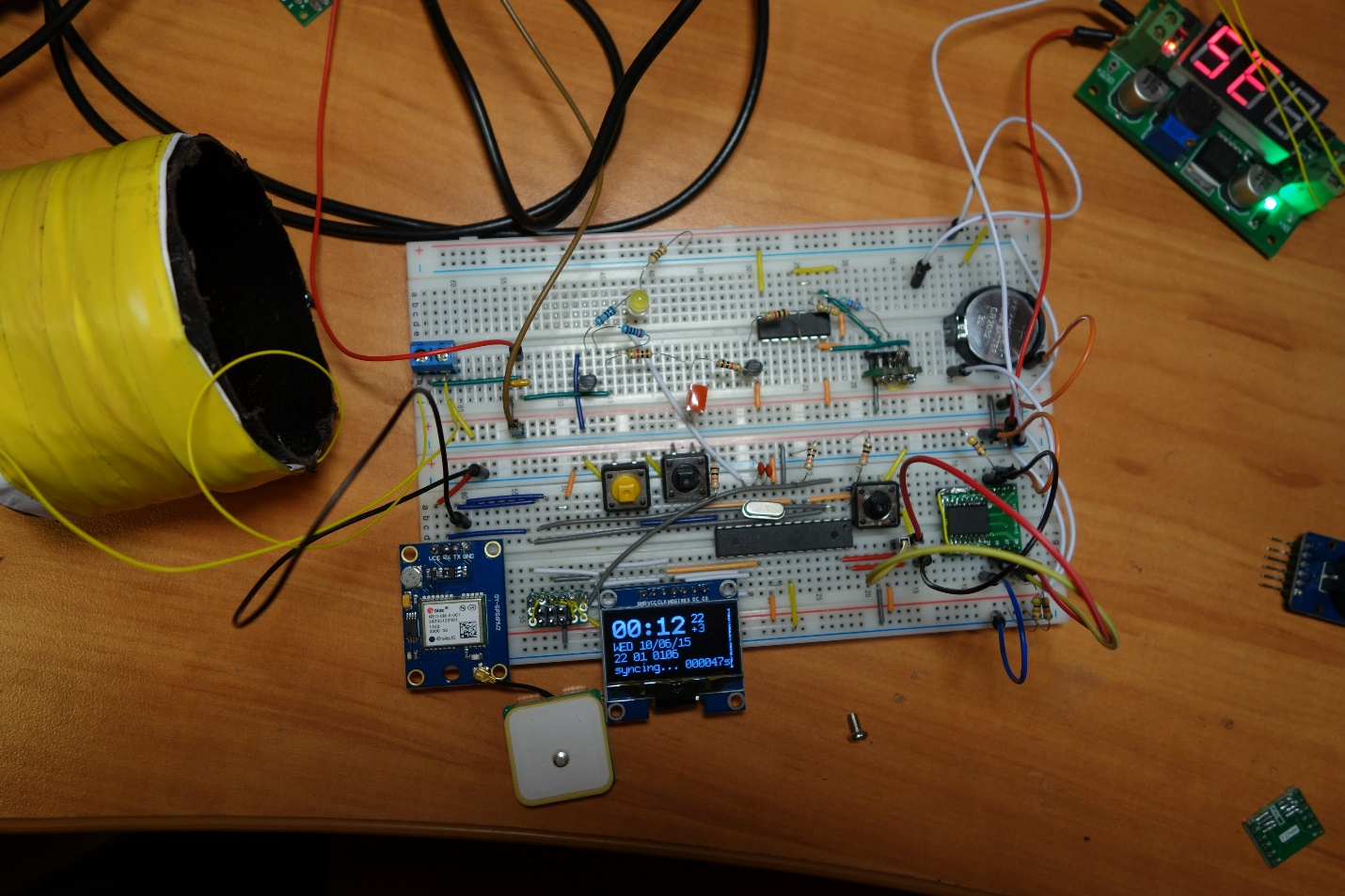
Finally managed to assemble a full-featured device on the development board.
I found some links to interesting dyi in the enclosures. For me, it was important that the device had a neat look. I saw several videos where atmega328 is stitched in Arduino. The firmware by this time was already difficult. To transfer it to something else did not want to. Arduino IDE with such a scenario seemed to me a good tool. Stitched Arduino using usbasp, which also ordered in China.
I did not want to get involved in self-etched boards. Therefore, I decided that I would unsolder the device on a special breadboard for soldering. Therefore, the preferred chip in the dip package. In the same cases, when there are no good alternatives in the dip package, I used adapters.
Success in transmission allowed us to finally start experimenting with the transmitter and receiver. I put the transmitter on and wore watches across the room in search of a better signal. I found out that we will take it best when the antenna is directed with its axis on the clock. And the clock is at a distance of no more than a meter - one and a half. In addition, finally came the oscilloscope. He also allowed to get an understanding of the processes taking place. Conducted experiments with the coil, which is attached to the probes. One could see that the amplitude of the signal changes, confirming the observations with the clock. The maximum amplitude on the coil if it is near and along the antenna axis. One and a half meters is not enough. It was decided to increase the transmitter power. The question is how? In the circuit, which I took as a basis, 1 kΩ resistors were installed. I decided to reduce this resistance. In addition, measured the resistance of the antenna. It was about 300 ohms. Looking ahead I will say that here I did not think about the reactive resistance. But first things first. Reduced the resistance of the transmitting antenna due to the use of a 0.3 section wire.
In order to work for sure, I decided to install the step-up module for the transmitting part. And be able to turn it off to save energy. In this configuration, everything was noticeably better. There were many successful synchronizations within 2-3 meters on the transmitter axis. Outside the axis, successful syncs were a meter away.
To increase the voltage used lt1302. In addition, I found an interesting charge on ltc4054-4.2, which fit well with the concept of the device.
At this stage, I understood why datasheets are needed. They are very helpful when using ICs, especially when it comes to specialized devices. Connection diagrams lt1302 and ltc4054-4.2 I already took from datashita. And I got into the habit of putting in git, in addition to the schemes, the source codes also the datasheets of all the devices used.
So, I got close to the soldering project. At this point, I had a device map. And the project on fritzing, which repeated the breadboard.
Separate hemorrhoids - create your own components for fritzing. As it turned out, this is the nasty part at all in any CAD system.
Another task that lasts a long time - dilution of the board. This may take several days. But in principle, quite feasible. The main point: we place the elements, then we connect them. If something is inconveniently connected, try to rearrange the components a little.
Noticed a fritzing flaw. If you rearrange something on the breadboard or on the diagram, it affects the breadboard. And there can be extra connections. Therefore, with small changes in one place they need to be done in another. In general, try it, but it tires a lot. Although for simple fritzing schemes are not bad.
That's what happened.
Used a 15x9 breadboard. Sawed it in half. By the way, one more necessary device for radio handicrafts is Dremel.
Payal a couple of days. It seems to work. But there was a lot of mounted installation. It looked ugly.
They write that the boards need to be washed after soldering. Decided to try to wash. Used for this flux-off. But somehow it did not work out. Laundered on Saturday at work, when almost no one was. But he felt dizzy, although he used a little and carefully. In short, laundered and threw it. At the same time everything was washed off badly. While decided to score.
That's what happened.
Here is another GPS module. I wanted the device to run on battery for a long time. The GPS module consumes quite a lot, I decided to find a GPS device with the enable line so that it can be turned off. Enable didn't work for me. But the GPS on mtk3339 turned out that it consumes 2 times less than the neo-6m. 30ma against 60ma. And the mtk3339 GPS module can be immersed in sleep.
I assembled the device, hoping that after soldering, everything will work much better. But it did not happen. Old problems have surfaced - unstable synchronization. There was also a problem when turning on the device without a battery. It did not work. It was possible to find out that the problem arose because the step-up charged a large capacitor at start-up, and at the start the device consumed a large current, more than the current for which the power supply was calculated, which went into protection. Everything was fine with the battery, so for now I decided not to pay attention to the problem. Just picked up the capacitor, so that there was no interference and the shutdown happened less. I did not want to install the resistor, so as not to increase the already large consumption of the device. The device worked from strength - day. What did not satisfy the requirements. The problem with unstable synchronization was greatly reduced after I found an error in the protocol description on the Russian Wikipedia here . In the German version, everything was fine. I corrected the error on Wikipedia. It turned out that the amplitude should not fall by 15%, but to 15%. I noticed this by conducting experiments, but then I found and confirm, for example, in the German wiki. So, with synchronization everything was decided, but the radius was still small. On the display with the edge was a strip of debris, with which I could not overcome.
I did not like the switch that turns off the power. He was very cumbersome. In addition, in the transistor tester, I spied the idea that you can turn on the power by pressing a button that can be used for other purposes. Transistor tester does not consume energy in an idle mode.
The shape of the signal left much to be desired. Spectrum analyzer showed a lot of unnecessary harmonics.
I began to think how to improve the device. Googled another version of the synchronizer .
It is interesting in him that behind the logic element there is a filter on the differential amplifier lvm824, and behind it the amplifier on the transistor. Disassembled the device. Fortunately, it consisted of two parts. I used the logical part to control, and began to collect the transmitting part on the breadboard and experiment.
As it is, I did not want to take the scheme. Because the voltage drop across the bipolar transistor is 0.6 volts, and the supply voltage is already about 4v. He began to think what to do.
Considered options with sound amplifiers. But, firstly, they are designed for frequencies up to 40khz, and secondly, they have a voltage drop of 2 volts. Did not find anything suitable.
I have already met the characteristic rail-to-rail, which means that the amplifier works in the whole power range, so I began to look for similar ones. I realized that I need to understand how filters are made and calculated. Found resources where you can count filters .
With the filters had to suffer. I began to experiment with them, using step-up to enhance them. Step-up was adjustable, allowing you to set the balance between power and battery saving. But in no way was it possible to choose the filter parameters so that it would act for a wide range of input voltages.
The Q1 transistor in the circuit uses as an amplifier. In order not to lose 0.6 volts, I first decided to do the same on a field-effect transistor, but reading further about amplifiers, I found an interesting amplifier circuit - a pavement, which better amplifies the signal in antiphase. I tried such a circuit on lvm822 with a transistor at the output. The advantage of this scheme is that with the same power the signal amplitude doubles. This means that, ideally, power is quadrupled. I also noticed that there is an ad8532 microcircuit, which is sufficient for the output power for my purposes and thus does not need to be done to set the output transistor. Such a connection greatly reduced interference and allowed to abandon step up.
I also stumbled upon the second transmitter improvement by chance. I saw that the reactance of my oscillating circuit was 1.5 kOm. This limits transmitter power.
When I experimented with the level of the transfer to the coil, I thought that you can make a step-up transformer after the amplifier. Then from the amplifier output to the input of the antenna will be supplied more voltage. This was done by winding a few turns on the transmitting Antenna. There are about 200 turns on the antenna itself, and about 10 turns on another winding. The exact amount picked up by the oscilloscope and tester. By this time I already had a tester with a frequency meter.
Such changes gave a big increase in transmit power. Theoretically, the increase in power compared with the old scheme will be approximately 400 times. In addition, the signal became almost pure sinusoid. But I had to add blocking capacitors to the antenna, because of the constant component, which crawled into the signal.
The range has increased greatly. You could even synchronize the clock in another room, not paying attention to the location of the antenna.
But the device did not work at work. I think when a lot of computers are turned on - a lot of noise.
Another problem is that the transmitter sometimes did not start due to the fact that the generator did not start. This was solved by the fact that I grounded the quartz body and due to a more stable power supply.
Another problem was that I went too far in pursuit of amplification in the coupling coil. I understood what the problem was, increased the number of turns a little, losing in gain, but the work of the transmitting part became more stable. 100% is synchronized now for almost a year, every night.
In addition to the improvements of the transmitting part, I wanted to make the switch off as in a transistor tester, but there it is made on a bipolar transistor. In order to reduce losses, I decided to make it on a field with low resistance. Here I modeled it . Also tested on a breadboard. Everything was fine: the voltage drop was about 0.05v, which suited me.
I wanted to monitor energy efficiency. Therefore, I decided to build an ina139 ammeter. On the breadboard tried. But I had to look for resistance of 0.05Om.
The transmitter made it switchable all through the same AO3401 fieldbus (Rds = 60mOm). In total, the voltage drop is 0.1V at the transmitter.
Began to redo the scheme in fritzing. And then the fritzing began to show the worst side. The scheme began to fall apart. The connections already made remained, but the contacts were considered disconnected. Fix the problem failed. The more you fix, the more the scheme fell apart. At work by this time we organized a club of like-minded people. I became interested in acquaintances who use what for designing circuits. I was advised by kiCad and ToporLite. I redid the circuit on kiCad. Made new components that were not. It all took a lot of time. Used autotrace from topor. Basically liked it. A little later, I ran into deeptrace. But he did not dare to switch to it. Although I suspect that deeptrace is still better.
Immediately decided that I would not sharpen the dip. I will do everything on smd, but in order not to bother with etching, I will order the payment on Ali or in Zelenograd.
I had already prepared the hull for a long time. Therefore, the fee was diluted under the case.
Diluted fee for several days. And decided to still order in Zelenograd. Done quickly. It turned out beautifully. He began to unsolder and found several errors. I mixed up rx and tx gps. I confused + and 0 current sensor. Wrong with the dimensions of a couple of millimeters on each side. Holes for mounting the display did less than necessary. Somewhere on the components there was no mask. Incorrectly spread the linear stabilizer for power from 9V - well, it took into account its cooling. It was necessary to make a large polygon under it. And incorrectly spread the connector 9c. If the connector layout could be fixed, then overheating was difficult to get rid of. Therefore, I removed the 9v connector.
And there were a number of minor problems. The most unpleasant of the first two. I suffered with them for a very long time.
Another problem with the layout is that I did not carefully read the datasheet. Did not pay attention to how to part the GPS module. It turned out necessary to make a hole. All similar corrections made after Dremel. Some corrections had to be made by surface mounting. The worst was with the current sensor.
Generally soldering was difficult. The hardest thing was to unsolder the GPS module. Even without errors, adjacent tracks are very simply closed.
Missed with screen plume. Not very neat connector turned out. And bulky.
But the device has assembled. Again tried to wash the flux. This time, washed with isopropyl alcohol. So washed away much better and without consequences.
That's what happened.
Markers in the image above indicate errors found.
The final touch was to reduce consumption by controlling power, controlling consumption and using the solar battery to recharge the device.
Modified the fonts so that the firmware got into memory. Fixed a problem with a strip on the screen. It turned out that the Chinese sold me a screen on sh1106 instead of ssd1306 as it was written in the order. Well, God bless them.
For load control, use round robin database for current value. By the way, this experience was interesting even from the point of view of a programmer. There is little memory, and I wanted to store data for the year.
Another subtle point is the definition when gps synchronized time to turn it off. For this, we had to refine the gpstiny library.
Now with all the modifications the device works for about a month without charging.

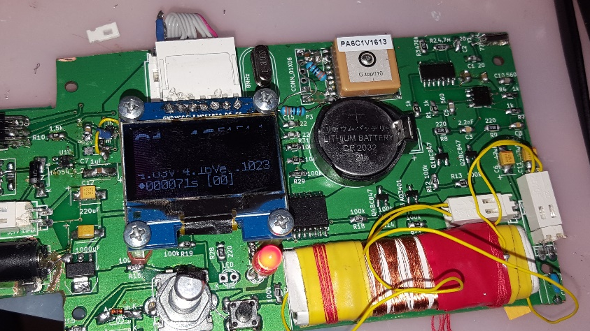
on the screen you can see that the consumption is 12 ma, but this is because of the maximum brightness of the screen.
I started the project in January 2015. I got my first results in April. Soldered on the breadboard in July. After that there was a break until March 2016. The iron version on the ordered board was assembled in June 2016. In July 31, 2016 was the last committe on the improvement of software. So I spent a year and a half on this device. Was it possible to approach the project differently? Maybe yes. But knowledge really lacked the beginning of the project. Now it is clear that for such work you need tools and some details. And it is clear what. Need knowledge. They appeared.
Of course, I still confuse the emitter and collector in the circuit, and I cannot tell from memory how the transistor works in each of the connection modes. But I know where to look quickly. A lot of money was spent on the project. It would probably be cheaper to buy a clock with GPS synchronization. Could costs be reduced? Yes you can, but not fundamentally. Can I sell a device? Yes you can. But the labor costs for its production are too large. It is more profitable just to work where I work now. I saw the sale of the device easier for 150 euros, and I need to collect 2-3 days. And I think it's hard to sell. So, I don’t see any commercial success with the device. Moreover, now began to appear clock with synchronization by gps. They will soon become cheaper. Did I enjoy the process? Yes, I received. It was very interesting to learn new things.As a programmer, it was useful for me to increase my horizons. Do I post it source? May be. If it is necessary for someone.
I made a new revision of the fee, but did not order it.
It is necessary to improve the power supply system of the controller. It is necessary to turn off the gps power completely, since in the standby mode, gps still eats 1 ma.
It is necessary to make the clock more accurate. There is an idea how to do it, but only on stm32. There you can use the function of adjusting the progress of the signal from the GPS. Also stm32 will allow to refuse an extra chip. Although ds3231 is more accurate, but for stm32 it is possible to make an adjustment.
Try using an e-ink screen to save energy. Now basically the screen eats up the whole battery. It consumes about 4 ma from 6 ma in standby mode, when only the current time is shown. The transmitter consumes 60 ma when turned on. It is 20 minutes a day. GPS consumes 30 ma, but it synchronizes time in a minute.
Here I will describe how I worked on this project, what problems I faced, being a novice in electronics, interesting solutions that I came across while working on a project, and I will try to justify them. This text may be of interest to programmers who decide to engage in electronics. Therefore, on the programming side, many things will be omitted.
Device concept
The first thing I started is to collect information about the protocol, possible finished devices, and thought out the requirements for the device. I started thinking about the basic concept.
')
1. Synchronization must be performed within the room.
2. The synchronizer itself may have an error of 2s
3. The synchronizer should be for hours.
4. Must have a self-diagnostic system.
5. Must be battery powered. (I'm not sure I can make a device that can work safely on the network to others)
6. From the battery, the device should work for about a month.
7. Everything should be beautiful. Housing Screen. Buttons. Etc.
The first steps
Then I began to collect material about the protocol and similar devices. Somewhere on the German resources were some ready-made devices . Found a description of the protocol on Wikipedia .
Since this all started.
What is dcf77? This is a protocol in which the date and time is transmitted by zeros and units of an amplitude modulated signal. At the beginning of each second, the amplitude is reduced to 15% by 0.1 or 0.2 s. If the length of the reduced signal is 0.1 s, then 0, if 0.2 s, then 1. What is clearly visible when blinking the LED. Read more here and here .
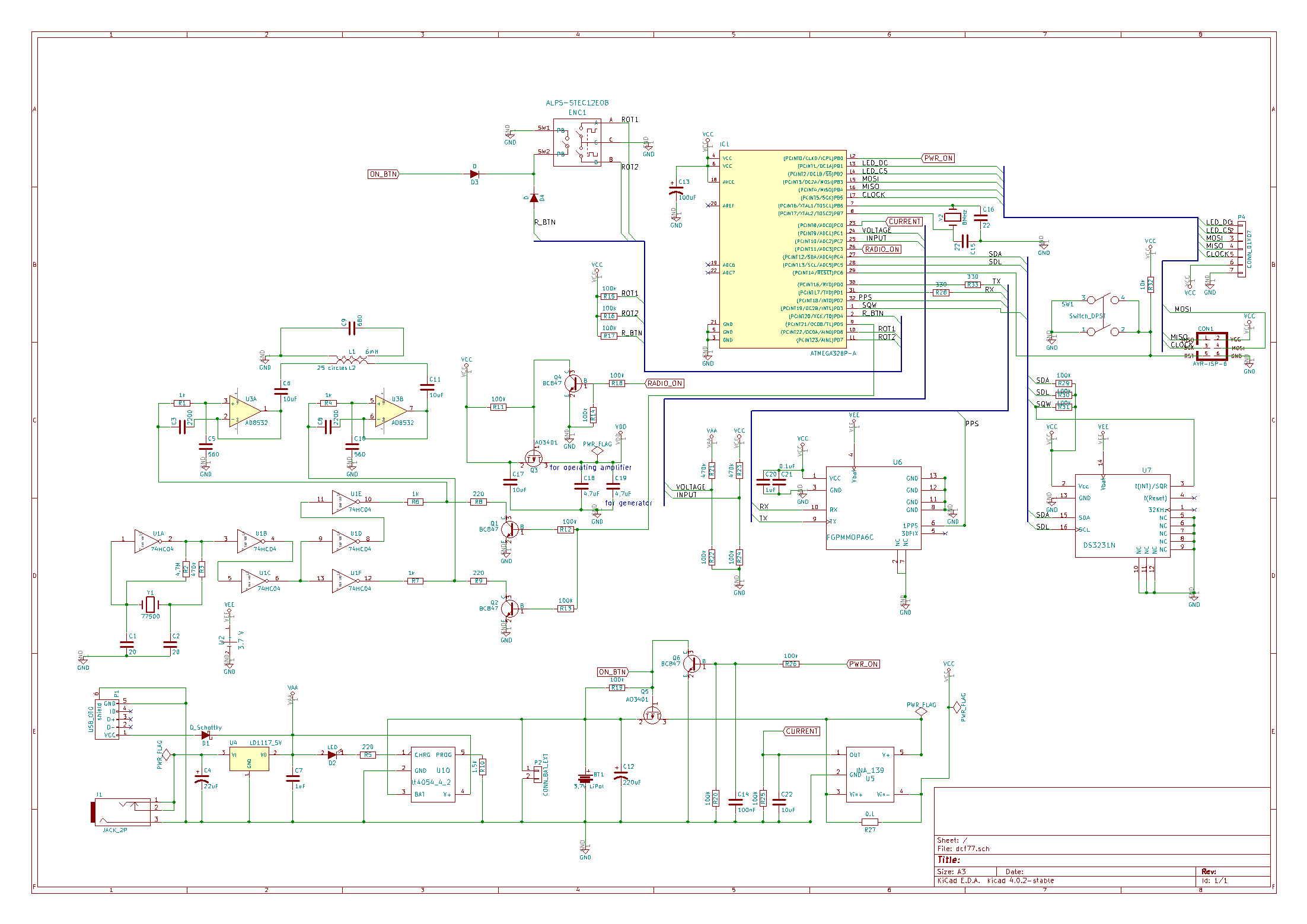
The first thing I did was implement the dcf77 protocol on a large computer in c ++. I did this quickly. It is clear that I tried to make flashing lights on arduino, therefore, it was not difficult to make flashing lights using dcf77 protocol on the LED. Photos or schemes of the very first versions I, unfortunately, did not survive. But the scheme was about the same as in the figure. Only without a generator and on the Arduino Uno.
On the way to such a scheme encountered some difficulties.
The first thing I encountered was that classes in the Arduino ide in the ino file cannot be implemented. I had to rewrite everything to C. I did not immediately realize that it was possible to simply connect it from a separate file. This problem was resolved quickly.
Due to the fact that I started with the fact that the signal was visualized by the LED, the resistor was sequentially set to the LED at around 200 ohms (the picture is no longer the case). To make it shine brighter. This all led to the fact that the transistor was constantly ajar and the circuit did not work normally. At random, I guessed to put two diodes in series.
The transistor seems to be closing. But it somehow looked wildly, even for me, and I realized that I needed to study the theory. Ase know very important. At least how the transistor works in key mode. And here I encountered the following problem: few details and few tools. For example, to make an antenna, you need a wire and ferrite. From China to wait for them for a long time. Fortunately, the hex invertor was in the Arduino starter. But I did not find quartz at 77500 in Russia at all, and even in China, at ali, he was only in one place, a batch of 50 pieces. By this time, I already realized that even if I put together a generator, I would not even be able to understand whether it works or not. And I realized that I needed tools: I needed a frequency meter and / or an oscilloscope. This gave me a break in the work on the device. And I began to study electronics. Listened to a number of YouTube videos on electronics, for example, this . Related articles. Articles on antennas. Very worried that the antennas for this frequency should be about 700 meters long. But still decided to try to make a magnetic antenna in the receivers .
An antenna needs a circuit from a magnetic coil and a capacitor in resonance. Resonance must somehow be sought. This led to the transistor tester project. He also wanted to implement it in between. There was an inductance meter there, and I had a few Arduino mini (plz Arduino haters, don't react right away. Then I corrected a little). But I realized that I was not ready to do it myself, ordered DYI, looked at his scheme and found his source .
Also learned about some useful programs for the phone, it is EveryCircuit and ElectroDroid. ElectroDroid I at this moment used to calculate the resonance of the antenna. EveryCircuit allows you to simulate small schemes on the phone. Decided to document and scheme. Somewhere on the Internet I saw a beautiful picture on a breadboard. I realized that this is what Fritzing does, in addition, he can design the circuit and the board. Began to use fritzing.
It was already time that the first parcels from China began to arrive. Something had to urgently order in the "chip and dip". This is where the first idea came about how to synchronize time. It was decided to synchronize on the wifi module esp8266.
Stumbled upon a similar project . I decided to take the main ideas from it. The radio part is completely borrowed from it. It was impossible to use it without rework, because:
1. It is rated at 12 volts.
2. Based on microcontroller pic.
First successes
As the details arrived, I began to improve the device. After the quartz and the transistor tester arrived, it became possible to finally assemble the first version capable of transmitting time. Wound the coil on a ferrite rod - this is the antenna. Looked at her inductance. Picked up capacitors of 100 pf. All kind of collected. Should work. And does not work. And, of course, the problem cannot be diagnosed. The oscilloscope has not arrived yet. Even the multimer is the easiest. According to him, little can be understood. It is good that my father-in-law had instruments and an oscilloscope and a frequency meter. I went to him with my device. We looked at the frequency meter like the frequency is. We looked at the oscilloscope, too, like nothing. The sine is not clear, but still looks like. I went home to understand further. The problem is that how to understand it is not clear. By the clock you can understand only if they saw the signal or not. To understand the error is impossible. But nevertheless, it is clear that the problem is not in the radio part, but in the modulator. I tried to vary the parameters. Without going far from the description from Wikipedia. In the end, I decided to lengthen the pulses on in the frequency modulator. And at that moment the clock finally hooked the signal. And, after several attempts, AFTERMAN succeeded in performing the first synchronization. Then it was decided to do time synchronization on the device itself.
In the process of searching for problems, I also discovered that digitalwrite works inefficiently.
Redid everything so that it does not use. Then I met this in other sources. But for the first time I saw it here . This was the first retreat from the Arduino.
I really like the oled screens, so it was decided to use the ssd1306 screen. But the library from adafruit is terrible. She is very slow. Uses a lot of RAM. Found an alternative to u8glib . I really liked.
The first solution I tried was based on the esp8266 module and implied time synchronization via the Internet. But I did not like the fact that it is rather difficult to connect through this module. And at that moment it was not very stable. Therefore, it occurred to me to try time synchronization via GPS. The module for ardino was like that. The firmware for synchronization via GPS was easier, but there were problems that I encountered in the future.
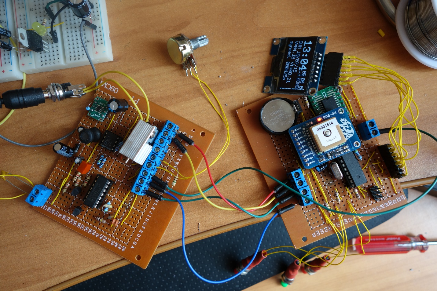
Finally managed to assemble a full-featured device on the development board.
Denial of Arduinio
I found some links to interesting dyi in the enclosures. For me, it was important that the device had a neat look. I saw several videos where atmega328 is stitched in Arduino. The firmware by this time was already difficult. To transfer it to something else did not want to. Arduino IDE with such a scenario seemed to me a good tool. Stitched Arduino using usbasp, which also ordered in China.
I did not want to get involved in self-etched boards. Therefore, I decided that I would unsolder the device on a special breadboard for soldering. Therefore, the preferred chip in the dip package. In the same cases, when there are no good alternatives in the dip package, I used adapters.
Transmission Improvement
Success in transmission allowed us to finally start experimenting with the transmitter and receiver. I put the transmitter on and wore watches across the room in search of a better signal. I found out that we will take it best when the antenna is directed with its axis on the clock. And the clock is at a distance of no more than a meter - one and a half. In addition, finally came the oscilloscope. He also allowed to get an understanding of the processes taking place. Conducted experiments with the coil, which is attached to the probes. One could see that the amplitude of the signal changes, confirming the observations with the clock. The maximum amplitude on the coil if it is near and along the antenna axis. One and a half meters is not enough. It was decided to increase the transmitter power. The question is how? In the circuit, which I took as a basis, 1 kΩ resistors were installed. I decided to reduce this resistance. In addition, measured the resistance of the antenna. It was about 300 ohms. Looking ahead I will say that here I did not think about the reactive resistance. But first things first. Reduced the resistance of the transmitting antenna due to the use of a 0.3 section wire.
In order to work for sure, I decided to install the step-up module for the transmitting part. And be able to turn it off to save energy. In this configuration, everything was noticeably better. There were many successful synchronizations within 2-3 meters on the transmitter axis. Outside the axis, successful syncs were a meter away.
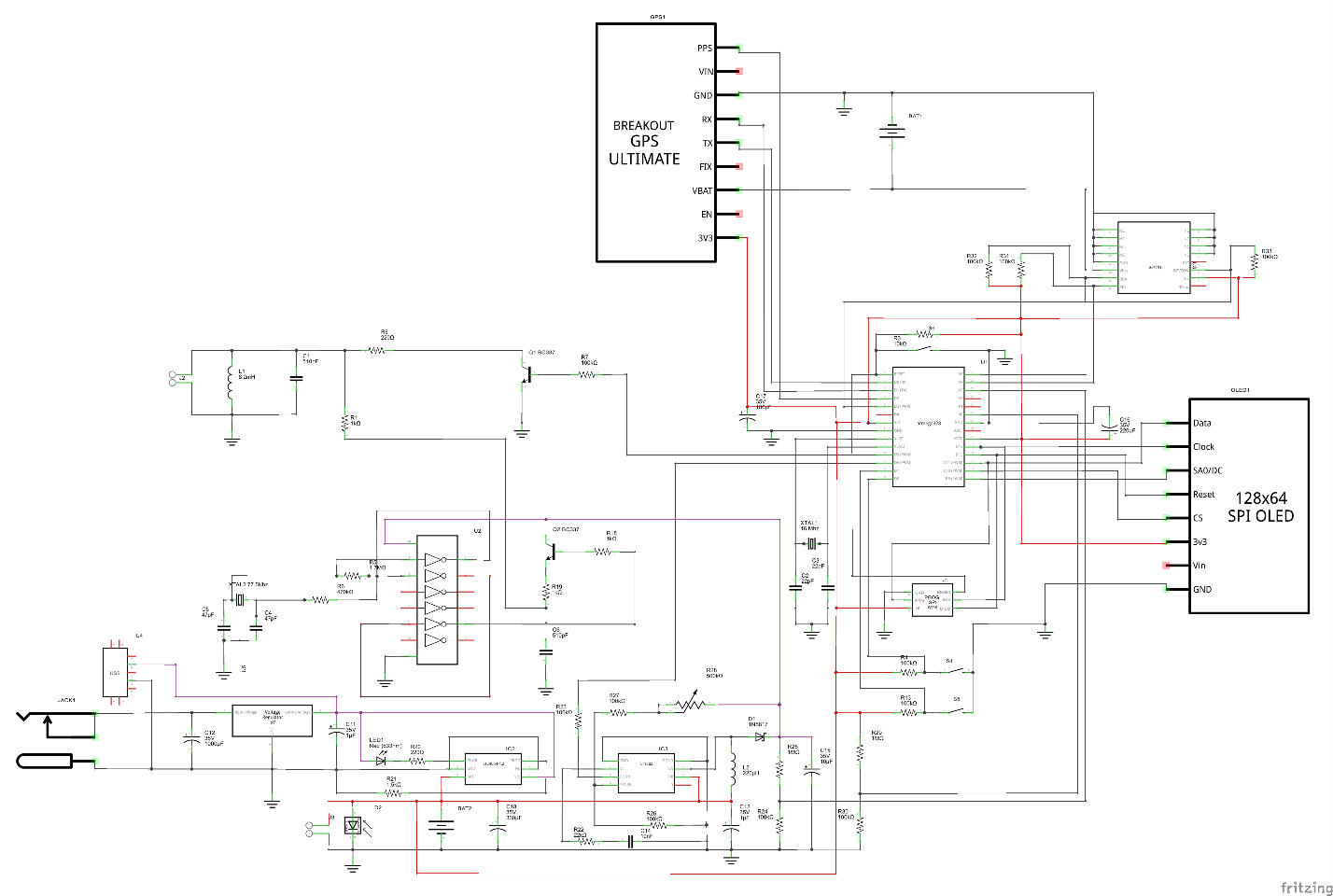
To increase the voltage used lt1302. In addition, I found an interesting charge on ltc4054-4.2, which fit well with the concept of the device.
At this stage, I understood why datasheets are needed. They are very helpful when using ICs, especially when it comes to specialized devices. Connection diagrams lt1302 and ltc4054-4.2 I already took from datashita. And I got into the habit of putting in git, in addition to the schemes, the source codes also the datasheets of all the devices used.
First attempt to assemble a device
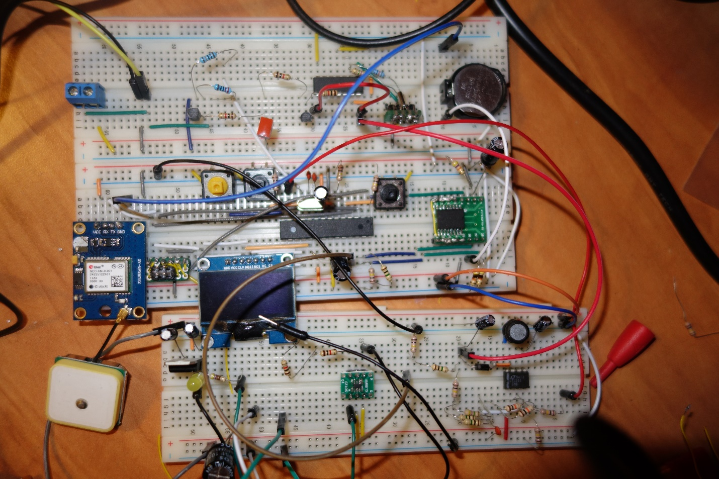
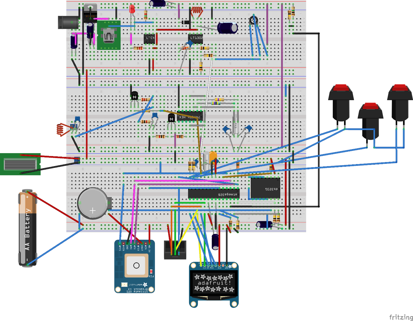
So, I got close to the soldering project. At this point, I had a device map. And the project on fritzing, which repeated the breadboard.
Separate hemorrhoids - create your own components for fritzing. As it turned out, this is the nasty part at all in any CAD system.
Another task that lasts a long time - dilution of the board. This may take several days. But in principle, quite feasible. The main point: we place the elements, then we connect them. If something is inconveniently connected, try to rearrange the components a little.
Noticed a fritzing flaw. If you rearrange something on the breadboard or on the diagram, it affects the breadboard. And there can be extra connections. Therefore, with small changes in one place they need to be done in another. In general, try it, but it tires a lot. Although for simple fritzing schemes are not bad.
That's what happened.
Used a 15x9 breadboard. Sawed it in half. By the way, one more necessary device for radio handicrafts is Dremel.
Payal a couple of days. It seems to work. But there was a lot of mounted installation. It looked ugly.
They write that the boards need to be washed after soldering. Decided to try to wash. Used for this flux-off. But somehow it did not work out. Laundered on Saturday at work, when almost no one was. But he felt dizzy, although he used a little and carefully. In short, laundered and threw it. At the same time everything was washed off badly. While decided to score.
That's what happened.
Here is another GPS module. I wanted the device to run on battery for a long time. The GPS module consumes quite a lot, I decided to find a GPS device with the enable line so that it can be turned off. Enable didn't work for me. But the GPS on mtk3339 turned out that it consumes 2 times less than the neo-6m. 30ma against 60ma. And the mtk3339 GPS module can be immersed in sleep.
Rethinking the project
I assembled the device, hoping that after soldering, everything will work much better. But it did not happen. Old problems have surfaced - unstable synchronization. There was also a problem when turning on the device without a battery. It did not work. It was possible to find out that the problem arose because the step-up charged a large capacitor at start-up, and at the start the device consumed a large current, more than the current for which the power supply was calculated, which went into protection. Everything was fine with the battery, so for now I decided not to pay attention to the problem. Just picked up the capacitor, so that there was no interference and the shutdown happened less. I did not want to install the resistor, so as not to increase the already large consumption of the device. The device worked from strength - day. What did not satisfy the requirements. The problem with unstable synchronization was greatly reduced after I found an error in the protocol description on the Russian Wikipedia here . In the German version, everything was fine. I corrected the error on Wikipedia. It turned out that the amplitude should not fall by 15%, but to 15%. I noticed this by conducting experiments, but then I found and confirm, for example, in the German wiki. So, with synchronization everything was decided, but the radius was still small. On the display with the edge was a strip of debris, with which I could not overcome.
I did not like the switch that turns off the power. He was very cumbersome. In addition, in the transistor tester, I spied the idea that you can turn on the power by pressing a button that can be used for other purposes. Transistor tester does not consume energy in an idle mode.
The shape of the signal left much to be desired. Spectrum analyzer showed a lot of unnecessary harmonics.
I began to think how to improve the device. Googled another version of the synchronizer .
It is interesting in him that behind the logic element there is a filter on the differential amplifier lvm824, and behind it the amplifier on the transistor. Disassembled the device. Fortunately, it consisted of two parts. I used the logical part to control, and began to collect the transmitting part on the breadboard and experiment.
As it is, I did not want to take the scheme. Because the voltage drop across the bipolar transistor is 0.6 volts, and the supply voltage is already about 4v. He began to think what to do.
Considered options with sound amplifiers. But, firstly, they are designed for frequencies up to 40khz, and secondly, they have a voltage drop of 2 volts. Did not find anything suitable.
I have already met the characteristic rail-to-rail, which means that the amplifier works in the whole power range, so I began to look for similar ones. I realized that I need to understand how filters are made and calculated. Found resources where you can count filters .
With the filters had to suffer. I began to experiment with them, using step-up to enhance them. Step-up was adjustable, allowing you to set the balance between power and battery saving. But in no way was it possible to choose the filter parameters so that it would act for a wide range of input voltages.
The Q1 transistor in the circuit uses as an amplifier. In order not to lose 0.6 volts, I first decided to do the same on a field-effect transistor, but reading further about amplifiers, I found an interesting amplifier circuit - a pavement, which better amplifies the signal in antiphase. I tried such a circuit on lvm822 with a transistor at the output. The advantage of this scheme is that with the same power the signal amplitude doubles. This means that, ideally, power is quadrupled. I also noticed that there is an ad8532 microcircuit, which is sufficient for the output power for my purposes and thus does not need to be done to set the output transistor. Such a connection greatly reduced interference and allowed to abandon step up.
I also stumbled upon the second transmitter improvement by chance. I saw that the reactance of my oscillating circuit was 1.5 kOm. This limits transmitter power.
When I experimented with the level of the transfer to the coil, I thought that you can make a step-up transformer after the amplifier. Then from the amplifier output to the input of the antenna will be supplied more voltage. This was done by winding a few turns on the transmitting Antenna. There are about 200 turns on the antenna itself, and about 10 turns on another winding. The exact amount picked up by the oscilloscope and tester. By this time I already had a tester with a frequency meter.
Such changes gave a big increase in transmit power. Theoretically, the increase in power compared with the old scheme will be approximately 400 times. In addition, the signal became almost pure sinusoid. But I had to add blocking capacitors to the antenna, because of the constant component, which crawled into the signal.
The range has increased greatly. You could even synchronize the clock in another room, not paying attention to the location of the antenna.
But the device did not work at work. I think when a lot of computers are turned on - a lot of noise.
Another problem is that the transmitter sometimes did not start due to the fact that the generator did not start. This was solved by the fact that I grounded the quartz body and due to a more stable power supply.
Another problem was that I went too far in pursuit of amplification in the coupling coil. I understood what the problem was, increased the number of turns a little, losing in gain, but the work of the transmitting part became more stable. 100% is synchronized now for almost a year, every night.
Final option
In addition to the improvements of the transmitting part, I wanted to make the switch off as in a transistor tester, but there it is made on a bipolar transistor. In order to reduce losses, I decided to make it on a field with low resistance. Here I modeled it . Also tested on a breadboard. Everything was fine: the voltage drop was about 0.05v, which suited me.
I wanted to monitor energy efficiency. Therefore, I decided to build an ina139 ammeter. On the breadboard tried. But I had to look for resistance of 0.05Om.
The transmitter made it switchable all through the same AO3401 fieldbus (Rds = 60mOm). In total, the voltage drop is 0.1V at the transmitter.
Began to redo the scheme in fritzing. And then the fritzing began to show the worst side. The scheme began to fall apart. The connections already made remained, but the contacts were considered disconnected. Fix the problem failed. The more you fix, the more the scheme fell apart. At work by this time we organized a club of like-minded people. I became interested in acquaintances who use what for designing circuits. I was advised by kiCad and ToporLite. I redid the circuit on kiCad. Made new components that were not. It all took a lot of time. Used autotrace from topor. Basically liked it. A little later, I ran into deeptrace. But he did not dare to switch to it. Although I suspect that deeptrace is still better.
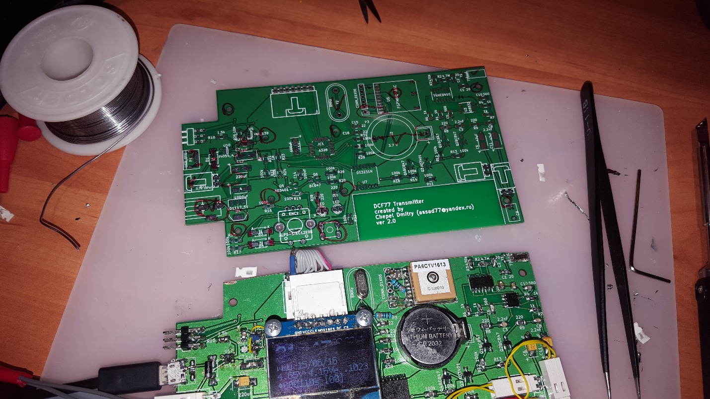
Immediately decided that I would not sharpen the dip. I will do everything on smd, but in order not to bother with etching, I will order the payment on Ali or in Zelenograd.
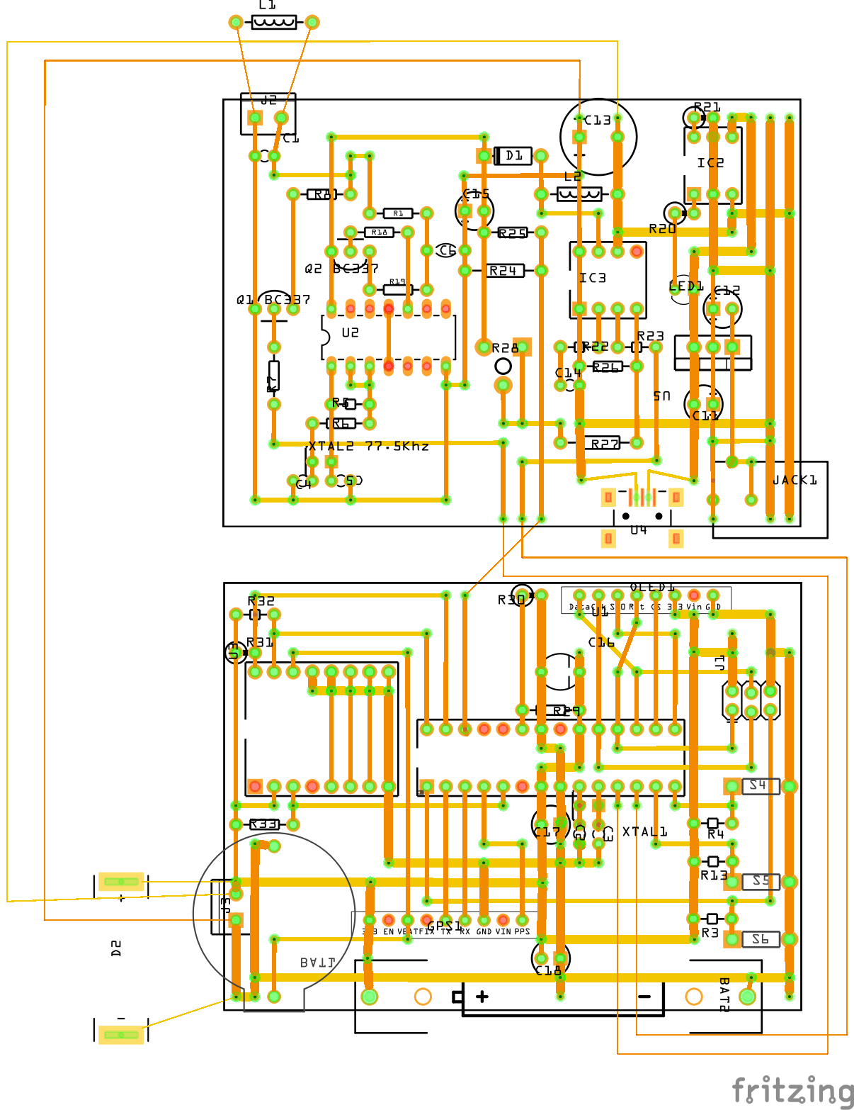
I had already prepared the hull for a long time. Therefore, the fee was diluted under the case.
Diluted fee for several days. And decided to still order in Zelenograd. Done quickly. It turned out beautifully. He began to unsolder and found several errors. I mixed up rx and tx gps. I confused + and 0 current sensor. Wrong with the dimensions of a couple of millimeters on each side. Holes for mounting the display did less than necessary. Somewhere on the components there was no mask. Incorrectly spread the linear stabilizer for power from 9V - well, it took into account its cooling. It was necessary to make a large polygon under it. And incorrectly spread the connector 9c. If the connector layout could be fixed, then overheating was difficult to get rid of. Therefore, I removed the 9v connector.
And there were a number of minor problems. The most unpleasant of the first two. I suffered with them for a very long time.
Another problem with the layout is that I did not carefully read the datasheet. Did not pay attention to how to part the GPS module. It turned out necessary to make a hole. All similar corrections made after Dremel. Some corrections had to be made by surface mounting. The worst was with the current sensor.
Generally soldering was difficult. The hardest thing was to unsolder the GPS module. Even without errors, adjacent tracks are very simply closed.
Missed with screen plume. Not very neat connector turned out. And bulky.
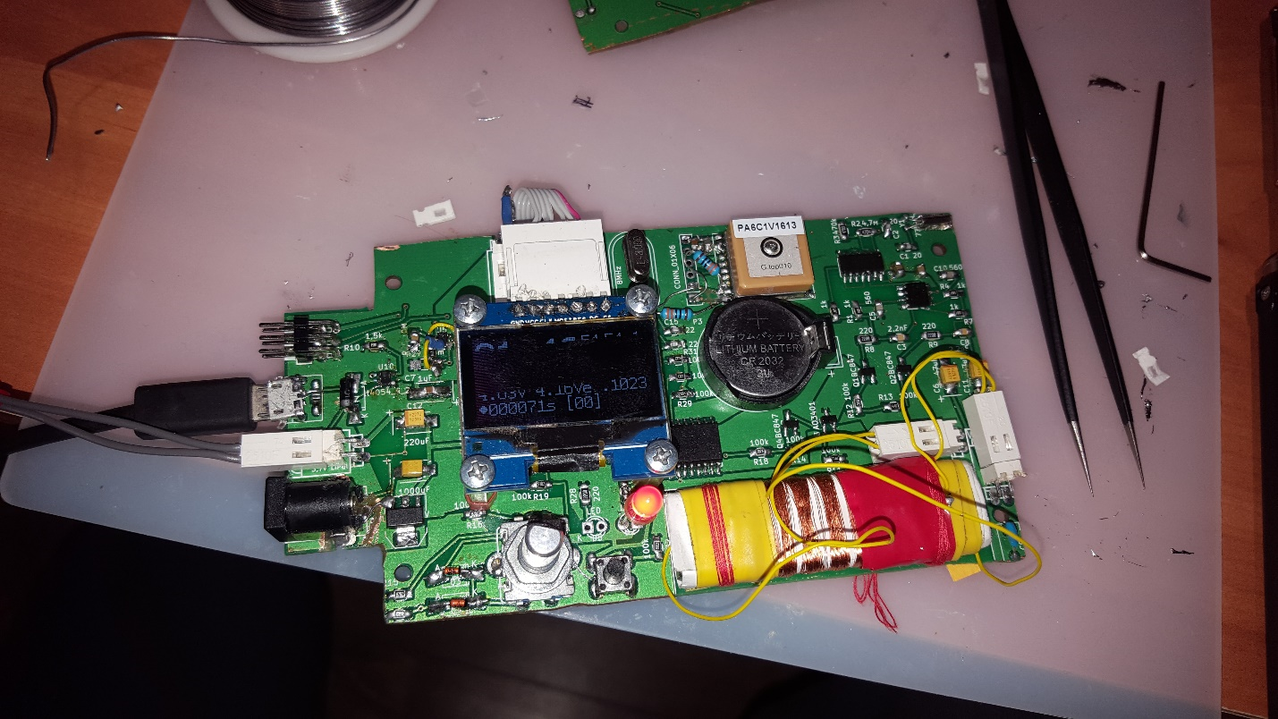
But the device has assembled. Again tried to wash the flux. This time, washed with isopropyl alcohol. So washed away much better and without consequences.
That's what happened.
Markers in the image above indicate errors found.
The final touches. Software update
The final touch was to reduce consumption by controlling power, controlling consumption and using the solar battery to recharge the device.
Modified the fonts so that the firmware got into memory. Fixed a problem with a strip on the screen. It turned out that the Chinese sold me a screen on sh1106 instead of ssd1306 as it was written in the order. Well, God bless them.
For load control, use round robin database for current value. By the way, this experience was interesting even from the point of view of a programmer. There is little memory, and I wanted to store data for the year.
Another subtle point is the definition when gps synchronized time to turn it off. For this, we had to refine the gpstiny library.
Now with all the modifications the device works for about a month without charging.
on the screen you can see that the consumption is 12 ma, but this is because of the maximum brightness of the screen.
Retrospective
I started the project in January 2015. I got my first results in April. Soldered on the breadboard in July. After that there was a break until March 2016. The iron version on the ordered board was assembled in June 2016. In July 31, 2016 was the last committe on the improvement of software. So I spent a year and a half on this device. Was it possible to approach the project differently? Maybe yes. But knowledge really lacked the beginning of the project. Now it is clear that for such work you need tools and some details. And it is clear what. Need knowledge. They appeared.
Of course, I still confuse the emitter and collector in the circuit, and I cannot tell from memory how the transistor works in each of the connection modes. But I know where to look quickly. A lot of money was spent on the project. It would probably be cheaper to buy a clock with GPS synchronization. Could costs be reduced? Yes you can, but not fundamentally. Can I sell a device? Yes you can. But the labor costs for its production are too large. It is more profitable just to work where I work now. I saw the sale of the device easier for 150 euros, and I need to collect 2-3 days. And I think it's hard to sell. So, I don’t see any commercial success with the device. Moreover, now began to appear clock with synchronization by gps. They will soon become cheaper. Did I enjoy the process? Yes, I received. It was very interesting to learn new things.As a programmer, it was useful for me to increase my horizons. Do I post it source? May be. If it is necessary for someone.
Possible improvements
I made a new revision of the fee, but did not order it.
It is necessary to improve the power supply system of the controller. It is necessary to turn off the gps power completely, since in the standby mode, gps still eats 1 ma.
It is necessary to make the clock more accurate. There is an idea how to do it, but only on stm32. There you can use the function of adjusting the progress of the signal from the GPS. Also stm32 will allow to refuse an extra chip. Although ds3231 is more accurate, but for stm32 it is possible to make an adjustment.
Try using an e-ink screen to save energy. Now basically the screen eats up the whole battery. It consumes about 4 ma from 6 ma in standby mode, when only the current time is shown. The transmitter consumes 60 ma when turned on. It is 20 minutes a day. GPS consumes 30 ma, but it synchronizes time in a minute.
Links
[1] journal.gladkiy.me/radiosinhronizatsiya-chasov-s-vy-shkoj-dcf77-v-germanii ( )
[2] www.elv.de/dcf-empfangsmodul-dcf-2.html
[3] ru.wikipedia.org/wiki/DCF77
[4] www.youtube.com/user/Zefar91/videos
[5] ikit.edu.sfu-kras.ru/CP_Electronics/pages/mm/index.html
digteh.ru/Sxemoteh/ShVklTrz/OK
[6] www.mikrocontroller.net/articles/AVR_Transistortester
[7] www.sundgren.se/1-recreation/2-electronics/dcf77_simulator.htm
[8] robotosha.ru/arduino/digitalwrite-optimizing-arduino.html
[9] www.youtube.com/watch?v=sNIMCdVOHOM&index=1&list=PLnOALHW_SnwoVHhkoyYadEQ9IuQ6nEj6M
[10] radiokot.ru/circuit/power/charger/33
[11] www.youtube.com/watch?v=lkWZuAnHa2Y
[12] pda.teron.ru/index.php?s=74c6aae329db3030d1b6cb47ad47051b&showtopic=909610&st=20
[13] sim.okawa-denshi.jp/en/OPseikiLowkeisan.htm
[14] pda.teron.ru/index.php?app=core&module=attach§ion=attach&attach_rel_module=post&attach_id=516440
[15] www.kaligraf.narod.ru/DCF77_protokol.html
[16] everycircuit.com/circuit/5072084672184320/p-mosfet-based-electronic-switch
Source: https://habr.com/ru/post/339052/
All Articles