On the issue of strangeness and systematic approach
Drop all the impossible, what remains will be the answer, however incredible it may be.
There is a section on “Sherlock Oms' Notes” on one foreign electronic resource where mysterious cases from engineering practice are considered (not only in the electronic part, but, as a rule, in it). I decided to start something similar, this is another story of engineering investigation.
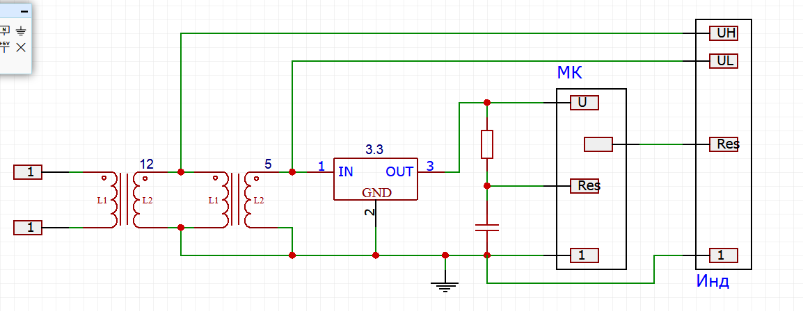
There is a certain device, an extract from the structural scheme of which is shown in Figure 1.
')
We see on it a pulse converter of input power to an intermediate bus 12 Volt, a pulse converter from 12 to 5 Volt, a linear stabilizer that forms a power supply of a microcontroller (MK) 3.3 Volts from 5, a reset circuit of the MC in the form of a delay on the integrator, the MC itself, which controls indicator through the interaction bus, including the reset signal, and the indicator itself, through which the user interacts. There is nothing special in this device structure, you can only pay attention to the fact that all of the above-mentioned domestic components (followed by advertising) are the companies Alexander Electric Don (sources of the MDM series), Milander (linear stabilizer and MK series 1986), KTC-MK (indicator type EL240).
A little about the indicator, since it is the main character of the story - not only is it domestic (the above-mentioned company actually assembles them, I myself saw, though from partially imported components), it also has an honest temperature range from -40 C without any heating is an electroluminescent ("plasma") indicator. But you have to pay for everything in this world - in this case we pay higher (compared to indicators on other technologies with comparable resolution) power consumption, weight and size parameters, pixel size, the need for two power supplies and of course money.
Devices of this type were designed, manufactured, and successfully performed their tasks for a long time, until one of them was “accidentally subjected to mechanical stress that went beyond the requirements for resistance to shocks according to the product specification” (hit the protrusion on the object ), which resulted in damage to the screen. The device was brought to us, the screen was replaced and they were going to give it to the consumer, but noticed one circumstance - the display changed a little.
The fact is that after switching on the device enters for some time (5-6 seconds) in the service mode, in which the operator’s representative can verify the software version number specified in the product passport (since this is a consumer who needs to have domestic components in the product - you already understand who it is - a common requirement) and then goes into the main mode of operation, and the working information is sent to the indicator. So, after repair in test mode, some pseudo-random information was present on the screen, and then normal operation began. A quick study showed that during the test mode the screen was not properly initialized (although the MC sent a pulse to it at the beginning of the work properly), and after reinitialization (before the start of the operating mode) it returned to normal.
There is a hypothesis - the first reset impulse is not fulfilled, since it falls on an unsteady indicator power. It is very easy to check it - after turning on the device, we send a reset signal to the MC input by closing the capacitor - after removing the short circuit, the program start procedure is rehearsed and the indicator correctly reflects the data starting from the test mode - the hypothesis was confirmed. Just in case, we carry out an additional study that more accurately tests the hypothesis - we short-circuit the capacitor when the power is turned off, then we turn it on and a second later we remove the tweezers - there is no defect, the display is tested in test mode. We accept the working hypothesis correctly and are looking for ways to correct the defect.
We look at the oscilloscope time diagram of signals at the time of launch and see that after the appearance of a stable power supply +12 (by the way, it takes off almost vertically, the source clearly has a good power reserve) +5 power (together with power +3.3) becomes stable after 80 msec ( the delay of switching on the second source, and the front is also very good, sharp), the MC reset signal disappears after another 1 ms, and the reset signal comes on the indicator after another 100 ms, as provided for in the program. Strange as it seems, everything seems to be normal and the discharge clearly falls on a stable diet, which means that the hypothesis must be changed. We assume that after one of the power supplies to the indicator, it is necessary to pause until a reset signal is given and this requirement is not currently being fulfilled. We look at the date in the part of the sequence of switching on the indicator and find that no requirements are made, the word is completely, there is only a requirement to refrain from transmitting information to the indicator for 3 ms after the completion of the reset, which is completely fulfilled. Some vague ones emerge (the device and firmware were developed to it 4 years ago, and comments in the program, of course, well, not completely absent, but close to this), the memory that two initializations are not without reason and apparently, from the first reset, not always the indicator was launched and, therefore, a delay is really necessary, and in a new instance of the screen it was necessary to increase it (well, it happened, with parameters not specified in the documentation, this happens). Well, let's estimate that, since we now see values on the order of hundreds of milliseconds, then the increase should be proportionate, at least tens of milliseconds, and it is better to add a hundred, especially since we fit into the requirements for the device in ready time with a large margin.
To begin with, we will determine where an increased delay is needed - from feeding 12 to dropping the screen or from feeding 5 to it. We are conducting another experiment - the source +5 has a work permit input, therefore, when the device is turned on, we short-circuit the permission input to its input minus (this is up to date at the source is permissible and even recommended) and the device starts up without a defect - it means that we need a delay after lifting 12 and launch 5. It is a little incomprehensible, I would still have fed the logical part of the device from 5, but I guess I don’t know everything until we agree.
Of course, the delay can be set even after the appearance of 5 before the start of the MK, while the automatic add delay from 12 to the reset, but this will require a significant change in the parameters of the chain (now there is a time constant of 1 msec) and will make the front very tight, which is usually not welcome, or after launching the MC until the formation of a reset on the indicator (but this requires a change in the program, which would be good to be postponed in case we cannot cope with iron doping).
Therefore, we put a delay circuit on the RC chain at the input of the inclusion of source 5 with a time constant of 100 ms and ... nothing happened - the defect remained on when turned on, although the oscillogram confirms that the delay is 100 ms longer. It is strange that either an increase in the delay is required even more (but even so, we have already done almost 300 ms), or the hypothesis about the location of the required delay is incorrect. We are conducting another experiment - we short-circuit the resolution of the source 5 to the input minus, turn on the device and release it after a second - and see that the defect has not disappeared. Yeah, so the delay is needed all the same between turning on 5 and resetting the screen. We correct the program and find out that with a delay of 120 ms the defect disappears, so for reliability we do 200 ms and enter a comment why it was done this way (in such situations you understand the need to comment on the text, which usually seems to be some unfortunate abstraction).
The problem is solved, the defect is eliminated, but the unpleasant residue remains - there are incomprehensibilities (I personally don’t like it when I don’t understand something, these misunderstandings have a nasty habit of then popping up at the most inopportune moment and hurting to hit in the back). In general, the “but it works the same” approach is absolutely not our approach, we must understand (well, or think that we understand) why the solution works. “It's not so scary if your program does not work and it’s not clear why. The worst case is when your program works, and it’s not clear why. ”
The first, not the main question - what is the delay, which is not described in the date. Well, everything is simple, Krivoruk developers have introduced some kind of change in the circuitry, such as a temporary lock to avoid races when turned on, and did not bother to check its impact on the device behavior and did not reflect the date. This happens all the time, although this does not in any way serve as an excuse for them (the developers), so I ask you to consider this post also as an appeal to the technical support of the manufacturer of the indicator. There is still the possibility that this is a defect of a specific indicator and in the old days I would behave like an instance in the absence of requirements for a delay in the specification and would consider and make up a complaint, but the old times have sunk into oblivion (I don’t know if this is good or bad, but it is a fact of “objective reality given to us in sensations” and reflections). I don’t have any indicator schemes, but I don’t have a particular desire to understand someone else’s scheme, so we came up with a plausible explanation and at this stage we are happy with this.
But the second misunderstanding is much more alarming - after all, the experiment initially clearly indicated the wrong cause of the defect (in fact, the experiment did not indicate anything, except for the fact that our interpretation of its results is erroneous), and this would have to be understood - this is our school of understanding what is happening which is unacceptable in principle. Once again we formulate a contradiction - if we turn off source 5 at the moment when the device is under power 12 and is functioning, the switch-on takes place without a defect, but if we delay turning on the source 5 from the very beginning of the power supply start, then there is a defect at the first start. In full accordance with the rules of TRIZ, a well-formulated contradiction suggests a mechanism for overcoming it. We hypothesize that if the indicator is already functioning correctly (the reset is completed), then turning off the power 5 does not lead to its return to its original (indefinite) state, that is, 12 it is somehow supported. To test this hypothesis, we conduct another experiment - we block source 5, turn on the device, release 5 and let the MC work, but do not reach the second reset, block again and repeat the procedure. We see that the test mode in this case (we do not reach the operating mode) always has a defect. If we allow the MC to reach the second reset and enter the operating mode, then all subsequent restarts of source 5 lead to the correct switching sequence. It is not very clear why this is done, but it is quite realizable, and we can even draw a diagram having a similar behavior.
Now that everything has become clear to us, we fix a new delay in the program and consider the task completely solved (until new results are obtained that will contradict the previously obtained ones), until an indicator instance is received, to which 200 ms of delay will not be enough.
Source: https://habr.com/ru/post/339000/
All Articles