The implementation of "Tetris" in the game "Life"
What began as an adventure ended in an odyssey.
This project was the culmination of the work of many users over the past year and a half. Although the team changed over time, the following authors participated in writing this article:
')
We also want to thank 7H3_H4CK3R, Conor O'Brien and many other users who have invested their work in solving this problem.
Due to the unprecedented scale of this task, the article is divided into several parts written by team members. Each participant wrote about their individual subtheme, approximately corresponding to the areas of the project in which it was involved.
It is also worth a look at the GitHub of our organization , in which we put all the code written to solve the problem. Questions can be asked in our development chat .
This project began as an answer to the Stackexchange question :
The main idea of this project was abstraction . Instead of directly developing “Tetris” in the game “Life”, we gradually expanded the abstraction being created. On each layer, we went further and further away from the difficulties of “Life” and approached the creation of a computer, which would be as easy to program as any other.
First, as a basis for the computer, we used OTCA-metapixels . These metapixels can emulate any rules of the game, similar to Life. Wireworld and Wireworld were important sources of inspiration for this project. We wanted to create a similar structure based on metapixels. Although it is not possible to emulate Wireworld using OTCA metapixels, you can set different rules for different metapixels and create structures of metapixels that work like Wireworld wires.
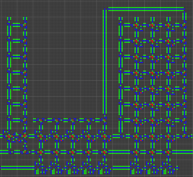
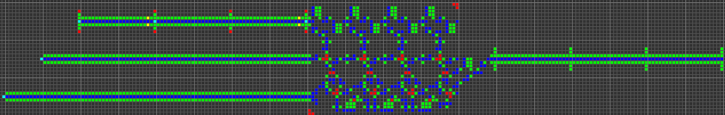
The next step was the creation of many fundamental logic gates that can be used as the basis of a computer. At this stage, we are already dealing with concepts similar to those of the real-world processor design. Here is an example of the OR gate, each cell of this image is actually a whole OTCA metapixel. You see how "electrons" (each of which represents a single bit of data) enter and exit the valve. Also visible are all the types of metapixels we used to create the computer: B / S - black background, B1 / S - blue, B2 / S - green, B12 / S1 - red.
From this we have developed a processor architecture. We spent a lot of time developing an architecture that would be both understandable and easy to implement. Wireworld uses a rudimentary transport-triggered architecture, but our project uses a much more flexible RISC architecture with multiple opcodes and addressing modes. We created the QFTASM assembly language (Quest for Tetris Assembly), which controlled the manufacture of the processor.
Also, our computer is asynchronous, which means that it is not controlled by a global clock. In the process of transferring data inside the computer, there is a synchronization signal. This means that we only need to track the local, not global, timings of the computer.
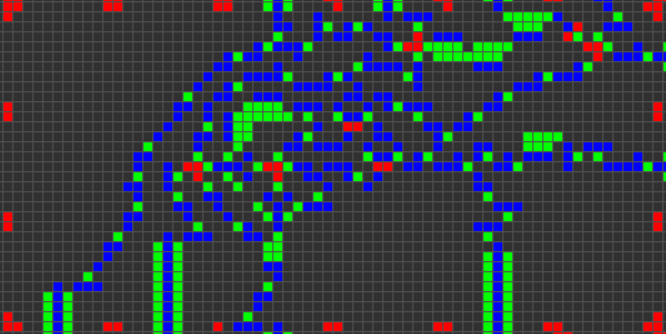
Here is an illustration of our processor architecture:
From this moment we can only implement the "Tetris" in the computer. To simplify the task, we have developed several ways to compile a high-level language in QFTASM. We have a basic Cogol language, a second, more advanced language is under development, and finally, we are creating a GCC backend. Now the program "Tetris" is written on Cogol and compiled from it.
After the final TFTRM QFTASM code was generated, the next steps were to build from this code into the appropriate ROM, and then from the meta pixels to the underlying Life game, on which our work will be completed.
Those who want to play Tetris without fiddling with the compiler can run the Tetris source code in the QFTASM interpreter . To view the entire game, specify the displayed addresses of RAM 3-32. Here is a permanent link for convenience: Tetris in QFTASM .
Game features:
Display
Our computer presents the Tetris field as a memory grid. Addresses 10-31 display the field, addresses 5-8 show the next figure, address 3 contains the score.
Input
Entering in the game is done by manually editing the contents of address 1 in RAM. When using the QFTASM interpreter, this means direct writing to address 1. See “Direct write to RAM” on the interpreter page. Each turn only requires changing one bit of RAM, and this input register is automatically reset after reading the input event.
Scoring system
The player receives a bonus for removing multiple lines in one turn.
OTCA-metapixel is a structure in the Life game in Konway, which can be used to simulate any cellular automaton similar to Life. I will quote LifeWiki (link below):
A cellular automaton, similar to Life , essentially means that cells are born and survive on the basis of how many of the eight neighboring cells live. These rules have the following syntax: the letter B followed by the number of living neighbors leading to birth, the slash, the letter S followed by the number of living neighbors supporting the life of the cell. A bit confusing, so I think it's better to give an example. The canonical Life game can be represented as a rule B3 / S23, which states that a dead cell surrounded by three neighbors becomes alive, and any living cell with two or three living neighbors remains alive. Otherwise, the cell dies.
Although the OTCA-metapixel is a 2048 x 2048 cell, it actually has a bounding box of 2058 x 2058 cells because it is overlapped by its diagonal neighbors with five cells in all directions. The overlapping cells are needed to intercept the “gliders” that are emitted to inform the metacell neighbors that it is included. Because of this, they will not affect other metapixels or move out of control. The rules of birth and survival are encoded in a special section of cells in the left part of the metapixel by the presence or absence of “eaters” in certain positions along two columns (one for birth, the other for survival). Regarding the recognition of the state of neighboring cells, this is what happens:
A more detailed outline of each aspect of the OTCA metapixel is presented on its website: How Does It Work? .
I created an online simulator of the rules of Life-like games, in which you can set the behavior of any cell in accordance with any rules similar to the rules of "Life." I called the simulator "Variations of Life". For brevity, then this name changed to “VarLife”. Here is its screenshot (link to the simulator: http://play.starmaninnovations.com/varlife/BeeHkfCpNR ):

Notable features:
The render-to-gif function is my favorite, because a lot of time was spent on its implementation. It was great when I finally completed it at seven in the morning. With its help, you can easily share the designs of VarLife with other people.
In general, the VarLife computer requires only four types of cells! Only eight states, taking into account the “dead” / “alive” states:
Use this short url to open VarLife with already coded rules: http://play.starmaninnovations.com/varlife/BeeHkfCpNR .
There are several different designs of conductors with different characteristics.
This is the simplest and the main conductor in VarLife, a strip of blue bounded by green stripes.
Short url: http://play.starmaninnovations.com/varlife/WcsGmjLiBF
This is a unidirectional conductor. That is, it will destroy all signals trying to pass in the opposite direction. In addition, it is one cell narrower than the main conductor.

Short url: http://play.starmaninnovations.com/varlife/ARWgUgPTEJ
There are also diagonal conductors, but they are almost never used.
Short url: http://play.starmaninnovations.com/varlife/kJotsdSXIj
In fact, there are many ways to create each individual gateway, so I will show only one example of each type. The first gif shows the AND, XOR and OR gateways, respectively. The basic idea is that the green cell acts as AND, the blue one as XOR, and the red one as OR, and all the other cells around them just provide the correct transmission.
Short url: http://play.starmaninnovations.com/varlife/EGTlKktmeI
The AND-NOT (ANT for short) gateway proved to be a vital component. This gateway transmits a signal from A if and only if there is no signal from B. That is, “A AND NOT B”.

Short url: http://play.starmaninnovations.com/varlife/RsZBiNqIUy
Although this is not really a gateway , the intersection of the conductors is very important and useful.
Short url: http://play.starmaninnovations.com/varlife/OXMsPyaNTC
By the way, there is no NOT gateway. This happened because without the incoming signal a permanent output should be created, which does not perform well with the many timings required by modern computer equipment. But in any case we managed to do without it.
In addition, many components were intentionally created in such a way as to fit into the bounding box 11 by 11 ( tile ), in which the signals take 11 ticks from the moment they enter the tile to exit the tile. This makes the components more modular and easier to connect together without having to adjust the conductors to provide space or timings.
About other gateways investigated / created in the process of studying the components of the schemes can be found in the post PhiNotPi: Building Blocks: Logic Gates .
In the process of developing computer hardware, KZhang came up with a variety of latency components shown below.
Delay on 4 clocks:
Short url: http://play.starmaninnovations.com/varlife/gebOMIXxdh
Delay of 5 cycles:
Short url: http://play.starmaninnovations.com/varlife/JItNjJvnUB
Delay for 8 clocks (three separate entry points):
Short url: http://play.starmaninnovations.com/varlife/nSTRaVEDvA
11 clock delay:
Short url: http://play.starmaninnovations.com/varlife/kfoADussXA
Delay for 12 clocks:
Short url: http://play.starmaninnovations.com/varlife/bkamAfUfud
14 clock latency:
Short url: http://play.starmaninnovations.com/varlife/TkwzYIBWln
Delay for 15 cycles (checked by comparison):
Short url: http://play.starmaninnovations.com/varlife/jmgpehYlpT
So, here are the main components of the VarLife schemes! For descriptions of the basic computer circuits, see the following section, written by KZhang!
Thanks to our knowledge of logical gateways and the overall structure of the processor, we can begin the development of all computer components.
A demultiplexer, or demux, is a critical component of ROM, RAM, and ALU. Depending on the given selector data, it sends the input signal to one of several output signals. It consists of three main parts: a series-parallel converter, a signal control device and a clock separator.
We start by converting the serial data of the selector to "parallel". This is done by strategically dividing and delaying the data so that the leftmost data bit crosses the clock signal in the leftmost 11x11 square, the next data bit crosses the clock signal in the next 11x11 square, and so on.
Although every bit of data will be output in every 11x11 square, every bit of data will overlap with a clock signal only once.
Next, we check if the parallel data matches the specified address.
We do this with the AND and ANT gateways used for clock and parallel data. However, we need to make sure that the parallel data is also output so that they can be compared again. Here are the gateways that I created as a result:

Finally, we simply divide the clock signal, connect several signal verification devices (one for each address / output), resulting in a multiplexer!
The ROM should receive an address as input, and send an instruction as an output to that address. We begin by using a multiplexer to direct the clock signal to one of the instructions. Then we need to generate a signal by touching several conductors and OR gateways. Touching the conductors allows the clock signal to pass through all 58 bits of the instruction, and also provides the movement of the generated signal (while parallel) through the ROM to the output.
Then we just need to convert the parallel signal into a serial one, and this ROM will be ready.
Currently, the ROM is generated by executing a script on Golly, which transmits the assembler code from the clipboard to the ROM.
These three logical gateways are used for bit-shifting, and they are more complex than regular AND, OR, XOR, etc. In order for these gateways to work, we first need to perform a clock delay for the appropriate time to “shift” the data.
The second argument passed to these gateways says that you need to perform an offset for so many bits.
For SL and SRL we need
This can be accomplished using multiple AND / ANT gateways and a multiplexer.
SRA is a little different, because when we shift, we need to copy the sign bit. We do this by applying AND to a clock signal with a sign bit, and then copying the output several times using the separators of the conductors and the OR gateways.
Many processor functions depend on the ability to store data. We can implement it with the help of two red cells B12 / S1. Two cells can keep each other on or off together. With the help of additional circuits of inclusion, reset and reading, we can create a simple SR-trigger.

By converting serial data into parallel, and then including several SR triggers, we can store the whole data word. Then, to retrieve the data again, we can simply read and reset all the triggers, and properly delay the data. This will allow us to store one (or several) data words while we are waiting for another. Due to this we will be able to synchronize two words of data received at different times.
This device keeps track of how many times it must perform addressing from RAM. It solves this problem with a device similar to the SR flip-flop: T-flip-flop. Each time a T-flip-flop receives input data, it changes its state: if it was turned on, it turns off, and vice versa. When a T-flip-flop changes its state, it sends an output pulse, which can be sent to another T-flip-flop, creating a two-bit counter.

To create a read counter, we need to transfer the counter to the appropriate addressing mode using two ANT gateways, and use the counter output signal to determine where to send the clock signal: to the ALU or to the RAM.
The read queue must keep track of which of the read counters sent the input data to RAM so that it can send the RAM output to the right place. To do this, we use several SR triggers: one trigger per input. When a signal is sent to the RAM from the read counter, the clock signal is split and turns on the SR trigger of the counter. Then, the RAM output goes along with the SR flip-flop through the AND gateway, and the clock signal from the RAM drops the SR flip-flop.
The ALU is similar in operation to the read queue in that it also uses the SR flip-flop to track where to send the signal. First, using the multiplexer, the SR trigger of the logic circuit corresponding to the opcode of the instruction is activated. Then, the values of the first and second arguments along with the SR flip-flop pass through the AND gateway, and then are passed to logical circuits. When passing the clock signal resets the trigger, so that the ALU can be used again.
RAM has become the most difficult part of this project. It required a very specific control of each SR trigger storing data. For reading, the address is transmitted to the multiplexer and transmitted to the RAM segments. Segments of RAM in parallel display the stored data, which is converted to a sequential view and output. For recording, the address is transferred to another multiplexer, the recorded data is converted from serial to parallel form, and RAM segments distribute the signal over RAM.
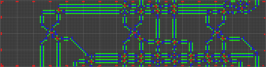
Metapixels 22x22 each segment of RAM has the following structure:
By connecting all the RAM, we get something like this:
With the help of all these components and the general computer architecture described in Part 1, we can build a working computer!
Downloadable files:
- Ready computer for "Tetris"
- ROM creation script, empty computer and computer for finding prime numbers
In short, our computer has a 16-bit asynchronous Harvard RISC architecture. When creating a processor manually, the RISC architecture ( computer with reduced instruction set ) is a practically mandatory requirement. In our case, this means that the number of opcodes is small, and, more importantly, all instructions are processed in a very similar way.
For reference, the Wireworld computer uses the transport-triggered architecture , in which the only instruction is
To keep our processor simple, while at the same time increasing its usability, we made several important decisions regarding its design:
1.
, . .
, . «» — , «» . , - , (PC). , : , TRUE.
: «, » (
. , little-endian, endian /. .
, . , Wireworld .
— ( , ). , , , , .
,
— , . : . (- ), , «» , «». /.
— « » (
. :
1.
PC . . . .
— 4 , 16 , 11 :
2. ( )
(, ). .
, . , ( , PC) .
(, ), . . , , 1 , PC.
, , . PC .
3.
, , . 16 , , . 2 .
, (, ). .
. : — , , . , , .
. — , , . . .
, — , , . , ( ), ( ).
4.
. , . .
, , . , , - 1 (
5.
, , , .
- , PC , , PC 1 (no-op). , PC , . , , PC , .
QFTASM. .
QFTASM . :
, , :
, . -32768 65536. .
Code example
:
, 1 . 28657 .
:
, 5. , , .
El'endia Starman - . , , .
«» , «». Cogol . «COBOL», «C of Game of Life», , Cogol C — , .
Cogol . , Cogol , :
( ) /, , .
:
( ) , . , , , . (,
. , . , .
( ) () .
QFTASM :
, . , .
« » , , . ,
QFTASM :
, , . false, . , , .
. , . :
, , 15-18:
,
— , , . ( ):
. , . , (). , . «» . , . . :
, . , . , ( ) .
,
. ( ). ( /), .
— , , : , , .
Cogol QFTASM . , , . .
«» Cogol, . QFTASM . : Tetris in QFTASM . ( Cogol), Cogol . , , ,
, Varlife «»!
, : , , . , .
K Zhang CreateROM.py , Python Golly, . : , . , :
:
Varlife :

, Varlife. …
«». «». , Varlife OTCA- . Varlife «».
, Golly ( metafier.py ), OTCA- «». , , Varlife. , Varlife .
, ( «») 1 436 x 5 082. 7 297 752 6 075 811 , 1 221 941 . OTCA-, 2048 x 2048 , 64 691 ( «») 23 920 ( «»). , 2 940 928 x 10 407 936 ( ) 29 228 828 720 79 048 585 231. 1 27-74 .
, , .
K Zhang metafier , MacroCell, , RLE. ( , metafier), (121 1,7 ), , . , MacroCell . Varlife.
«» .
, «», , ? Nothing like this. , :
Cogol «», .
2016 . - , , .
Python , , .
QFTASM : , , .
Python , .
, (
.
XML, .
, . , .
, , ,
. ,
, . :
turns into
, . «»
, . . . .
VariableStore . , .
, —
. ,
, , , . , . . , .
, . . . .
: :
, . , . , , , .
, .
, . ,
, . , . -
, . .
. . , . .
QFTASM. :
. , , QFTASM.
, , . Python, . , .
, .
, QFTASM
,
The task of creating a tetris processor of 2,940,928 x 10,295,296 in size
This project was the culmination of the work of many users over the past year and a half. Although the team changed over time, the following authors participated in writing this article:
')
- Phinotpi
- El'endia starman
- K Zhang
- Muddyfish
- Kritixi lithos
- Mego
- Quartata
We also want to thank 7H3_H4CK3R, Conor O'Brien and many other users who have invested their work in solving this problem.
Due to the unprecedented scale of this task, the article is divided into several parts written by team members. Each participant wrote about their individual subtheme, approximately corresponding to the areas of the project in which it was involved.
It is also worth a look at the GitHub of our organization , in which we put all the code written to solve the problem. Questions can be asked in our development chat .
Part 1: Review
This project began as an answer to the Stackexchange question :
This is a theoretical problem — it has neither a simple nor a trivial answer.
In the game “Life” of Conway there are such constructions as metapixels that allow the game “Life” to simulate any system of rules similar to “Life”. In addition, it is known that the game "Life" is Turing-complete.
Your task is to create a cellular automaton using the rules of Conway's Life game, which allows you to play Tetris.
The program should receive input by manually changing the state of the automaton in a certain generation representing an interruption (i.e., moving the figure left or right, turning, dropping down or randomly generating a new figure for placement on the field). A certain number of generations is considered waiting time. The result of the game is shown somewhere in the machine. The result should visually resemble the field for this "Tetris".
Your program will be evaluated according to the following criteria, in the following order (the lower criteria are additional to the higher):
- The size of the border rectangle - wins the rectangular field with the smallest area, completely containing the solution.
- Least change for input — wins the solution with the least amount of cells (at worst for your slot machine case) needed to manually configure as an interrupt.
- Fastest execution — wins the solution with the least number of generations to move forward one simulation cycle.
- The initial number of living cells wins the smallest number.
- The first published - wins the very first post with the decision.
The main idea of this project was abstraction . Instead of directly developing “Tetris” in the game “Life”, we gradually expanded the abstraction being created. On each layer, we went further and further away from the difficulties of “Life” and approached the creation of a computer, which would be as easy to program as any other.
First, as a basis for the computer, we used OTCA-metapixels . These metapixels can emulate any rules of the game, similar to Life. Wireworld and Wireworld were important sources of inspiration for this project. We wanted to create a similar structure based on metapixels. Although it is not possible to emulate Wireworld using OTCA metapixels, you can set different rules for different metapixels and create structures of metapixels that work like Wireworld wires.
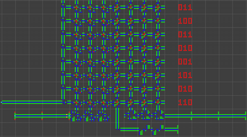
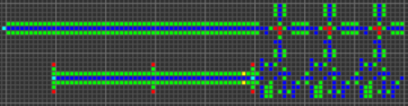
The next step was the creation of many fundamental logic gates that can be used as the basis of a computer. At this stage, we are already dealing with concepts similar to those of the real-world processor design. Here is an example of the OR gate, each cell of this image is actually a whole OTCA metapixel. You see how "electrons" (each of which represents a single bit of data) enter and exit the valve. Also visible are all the types of metapixels we used to create the computer: B / S - black background, B1 / S - blue, B2 / S - green, B12 / S1 - red.
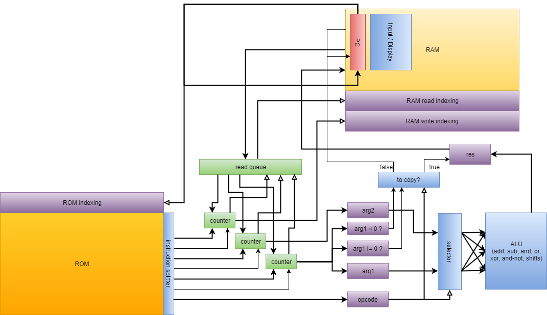
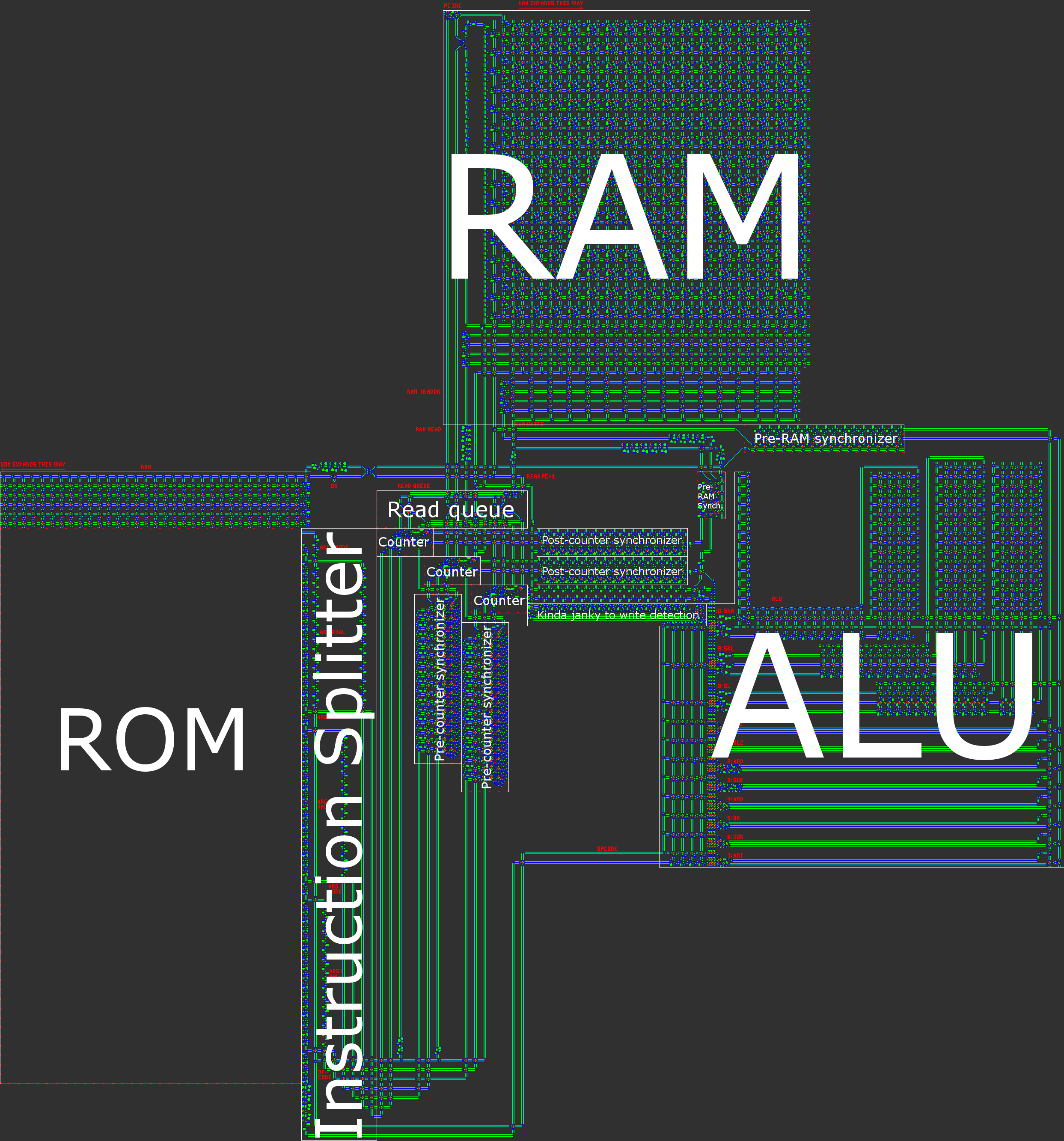
From this we have developed a processor architecture. We spent a lot of time developing an architecture that would be both understandable and easy to implement. Wireworld uses a rudimentary transport-triggered architecture, but our project uses a much more flexible RISC architecture with multiple opcodes and addressing modes. We created the QFTASM assembly language (Quest for Tetris Assembly), which controlled the manufacture of the processor.
Also, our computer is asynchronous, which means that it is not controlled by a global clock. In the process of transferring data inside the computer, there is a synchronization signal. This means that we only need to track the local, not global, timings of the computer.
Here is an illustration of our processor architecture:
From this moment we can only implement the "Tetris" in the computer. To simplify the task, we have developed several ways to compile a high-level language in QFTASM. We have a basic Cogol language, a second, more advanced language is under development, and finally, we are creating a GCC backend. Now the program "Tetris" is written on Cogol and compiled from it.
After the final TFTRM QFTASM code was generated, the next steps were to build from this code into the appropriate ROM, and then from the meta pixels to the underlying Life game, on which our work will be completed.
Launch of Tetris
Those who want to play Tetris without fiddling with the compiler can run the Tetris source code in the QFTASM interpreter . To view the entire game, specify the displayed addresses of RAM 3-32. Here is a permanent link for convenience: Tetris in QFTASM .
Game features:
- All 7 Tetromino
- Movement, rotation, smooth lowering of figures
- Clearing lines and scoring
- Show the next figure
- Player input adds randomness
Display
Our computer presents the Tetris field as a memory grid. Addresses 10-31 display the field, addresses 5-8 show the next figure, address 3 contains the score.
Input
Entering in the game is done by manually editing the contents of address 1 in RAM. When using the QFTASM interpreter, this means direct writing to address 1. See “Direct write to RAM” on the interpreter page. Each turn only requires changing one bit of RAM, and this input register is automatically reset after reading the input event.
value motion
1
2
4 ( )
8
16
Scoring system
The player receives a bonus for removing multiple lines in one turn.
1 = 1
2 = 2
3 = 4
4 = 8
Part 2: OTCA-metapixel and VarLife
Otca metapixel
OTCA-metapixel is a structure in the Life game in Konway, which can be used to simulate any cellular automaton similar to Life. I will quote LifeWiki (link below):
The OTCA-metapixel is a 2048 × 2048 cell of 35328 cells, created by Bryce Dew ... It has many advantages ... including the ability to emulate any cellular automaton similar to Life, and very noticeable when the scale is reduced, the cells are ON and OFF. ..
A cellular automaton, similar to Life , essentially means that cells are born and survive on the basis of how many of the eight neighboring cells live. These rules have the following syntax: the letter B followed by the number of living neighbors leading to birth, the slash, the letter S followed by the number of living neighbors supporting the life of the cell. A bit confusing, so I think it's better to give an example. The canonical Life game can be represented as a rule B3 / S23, which states that a dead cell surrounded by three neighbors becomes alive, and any living cell with two or three living neighbors remains alive. Otherwise, the cell dies.
Although the OTCA-metapixel is a 2048 x 2048 cell, it actually has a bounding box of 2058 x 2058 cells because it is overlapped by its diagonal neighbors with five cells in all directions. The overlapping cells are needed to intercept the “gliders” that are emitted to inform the metacell neighbors that it is included. Because of this, they will not affect other metapixels or move out of control. The rules of birth and survival are encoded in a special section of cells in the left part of the metapixel by the presence or absence of “eaters” in certain positions along two columns (one for birth, the other for survival). Regarding the recognition of the state of neighboring cells, this is what happens:
Stream 9-LWSS then walks around clockwise around the cell, losing the LWSS on each adjacent “on” cell that starts the honeybit reaction memory cell. The number of missing LWSSs is calculated by recognizing the position of the front LWSS by colliding with another LWSS from the opposite direction. This collision releases gliders that trigger another one or two honeybit reactions if there are no “feeders” determining the state of birth / survival.
A more detailed outline of each aspect of the OTCA metapixel is presented on its website: How Does It Work? .
Varlife
I created an online simulator of the rules of Life-like games, in which you can set the behavior of any cell in accordance with any rules similar to the rules of "Life." I called the simulator "Variations of Life". For brevity, then this name changed to “VarLife”. Here is its screenshot (link to the simulator: http://play.starmaninnovations.com/varlife/BeeHkfCpNR ):
Notable features:
- Switches the cells between live / dead states and colors the field according to different rules.
- The ability to start and stop the simulation, to perform one step at a time. It is also possible to perform a specified number of steps with a maximum speed or more slowly, with a speed that is set in cycles / s and ms / cycle.
- Has the ability to delete all living cells or completely reset the field to an empty state.
- It can change the size of the field and cells, as well as include horizontal and / or vertical toroidal convolution.
- Permanent links (which encode all url information) and short url (because sometimes there is too much information, but they are still useful).
- Rule sets with B / S assignment, colors and optional randomness.
- And the last - rendering gif!
The render-to-gif function is my favorite, because a lot of time was spent on its implementation. It was great when I finally completed it at seven in the morning. With its help, you can easily share the designs of VarLife with other people.
VarLife basic layout
In general, the VarLife computer requires only four types of cells! Only eight states, taking into account the “dead” / “alive” states:
- B / S (black / white), which serves as a buffer between all the components, because B / S cells can never be alive.
- B1 / S (blue / blue) is the main cell type used to propagate signals.
- B2 / S (green / yellow) - mainly used to control signals, protecting them from back propagation.
- B12 / S1 (red / orange) - used in some special situations, for example, when crossing signals and storing a bit of data.
Use this short url to open VarLife with already coded rules: http://play.starmaninnovations.com/varlife/BeeHkfCpNR .
Guides
There are several different designs of conductors with different characteristics.
This is the simplest and the main conductor in VarLife, a strip of blue bounded by green stripes.
Short url: http://play.starmaninnovations.com/varlife/WcsGmjLiBF
This is a unidirectional conductor. That is, it will destroy all signals trying to pass in the opposite direction. In addition, it is one cell narrower than the main conductor.
Short url: http://play.starmaninnovations.com/varlife/ARWgUgPTEJ
There are also diagonal conductors, but they are almost never used.
Short url: http://play.starmaninnovations.com/varlife/kJotsdSXIj
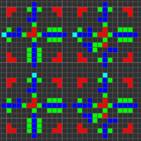
Gateways
In fact, there are many ways to create each individual gateway, so I will show only one example of each type. The first gif shows the AND, XOR and OR gateways, respectively. The basic idea is that the green cell acts as AND, the blue one as XOR, and the red one as OR, and all the other cells around them just provide the correct transmission.
Short url: http://play.starmaninnovations.com/varlife/EGTlKktmeI
The AND-NOT (ANT for short) gateway proved to be a vital component. This gateway transmits a signal from A if and only if there is no signal from B. That is, “A AND NOT B”.
Short url: http://play.starmaninnovations.com/varlife/RsZBiNqIUy
Although this is not really a gateway , the intersection of the conductors is very important and useful.
Short url: http://play.starmaninnovations.com/varlife/OXMsPyaNTC
By the way, there is no NOT gateway. This happened because without the incoming signal a permanent output should be created, which does not perform well with the many timings required by modern computer equipment. But in any case we managed to do without it.
In addition, many components were intentionally created in such a way as to fit into the bounding box 11 by 11 ( tile ), in which the signals take 11 ticks from the moment they enter the tile to exit the tile. This makes the components more modular and easier to connect together without having to adjust the conductors to provide space or timings.
About other gateways investigated / created in the process of studying the components of the schemes can be found in the post PhiNotPi: Building Blocks: Logic Gates .
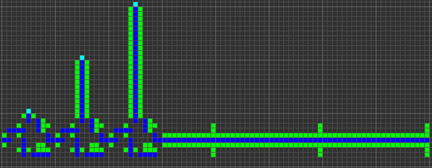
Delay components
In the process of developing computer hardware, KZhang came up with a variety of latency components shown below.
Delay on 4 clocks:
Short url: http://play.starmaninnovations.com/varlife/gebOMIXxdh
Delay of 5 cycles:
Short url: http://play.starmaninnovations.com/varlife/JItNjJvnUB
Delay for 8 clocks (three separate entry points):
Short url: http://play.starmaninnovations.com/varlife/nSTRaVEDvA
11 clock delay:
Short url: http://play.starmaninnovations.com/varlife/kfoADussXA
Delay for 12 clocks:
Short url: http://play.starmaninnovations.com/varlife/bkamAfUfud
14 clock latency:
Short url: http://play.starmaninnovations.com/varlife/TkwzYIBWln
Delay for 15 cycles (checked by comparison):
Short url: http://play.starmaninnovations.com/varlife/jmgpehYlpT
So, here are the main components of the VarLife schemes! For descriptions of the basic computer circuits, see the following section, written by KZhang!
Part 3: Equipment
Thanks to our knowledge of logical gateways and the overall structure of the processor, we can begin the development of all computer components.
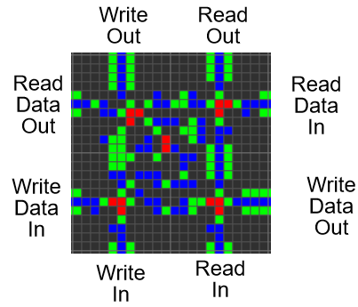
Demultiplexer
A demultiplexer, or demux, is a critical component of ROM, RAM, and ALU. Depending on the given selector data, it sends the input signal to one of several output signals. It consists of three main parts: a series-parallel converter, a signal control device and a clock separator.
We start by converting the serial data of the selector to "parallel". This is done by strategically dividing and delaying the data so that the leftmost data bit crosses the clock signal in the leftmost 11x11 square, the next data bit crosses the clock signal in the next 11x11 square, and so on.
Although every bit of data will be output in every 11x11 square, every bit of data will overlap with a clock signal only once.
Next, we check if the parallel data matches the specified address.
We do this with the AND and ANT gateways used for clock and parallel data. However, we need to make sure that the parallel data is also output so that they can be compared again. Here are the gateways that I created as a result:
Finally, we simply divide the clock signal, connect several signal verification devices (one for each address / output), resulting in a multiplexer!
ROM
The ROM should receive an address as input, and send an instruction as an output to that address. We begin by using a multiplexer to direct the clock signal to one of the instructions. Then we need to generate a signal by touching several conductors and OR gateways. Touching the conductors allows the clock signal to pass through all 58 bits of the instruction, and also provides the movement of the generated signal (while parallel) through the ROM to the output.
Then we just need to convert the parallel signal into a serial one, and this ROM will be ready.
Currently, the ROM is generated by executing a script on Golly, which transmits the assembler code from the clipboard to the ROM.
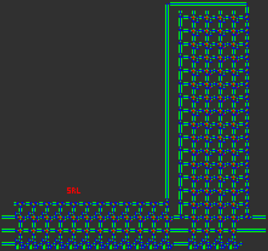
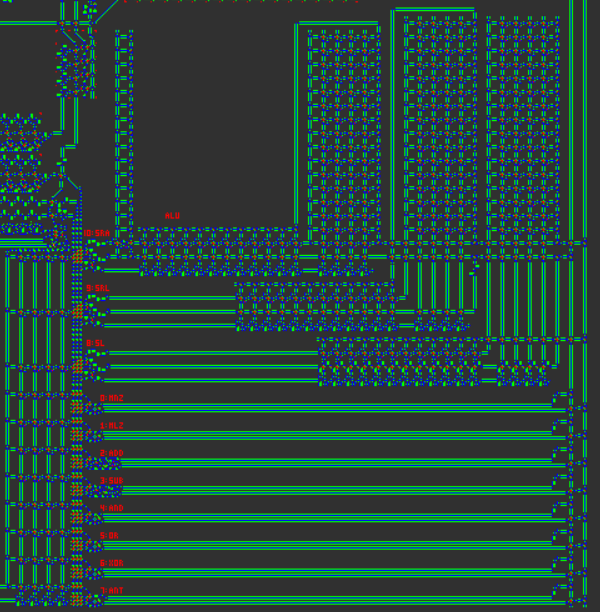
SRL, SL, SRA
These three logical gateways are used for bit-shifting, and they are more complex than regular AND, OR, XOR, etc. In order for these gateways to work, we first need to perform a clock delay for the appropriate time to “shift” the data.
The second argument passed to these gateways says that you need to perform an offset for so many bits.
For SL and SRL we need
- Ensure that the 12 most significant bits are not included (otherwise the output will be 0), and
- Perform data delay at the right time based on 4 less significant bits.
This can be accomplished using multiple AND / ANT gateways and a multiplexer.
SRA is a little different, because when we shift, we need to copy the sign bit. We do this by applying AND to a clock signal with a sign bit, and then copying the output several times using the separators of the conductors and the OR gateways.
Trigger Set-Reset (SR)
Many processor functions depend on the ability to store data. We can implement it with the help of two red cells B12 / S1. Two cells can keep each other on or off together. With the help of additional circuits of inclusion, reset and reading, we can create a simple SR-trigger.
Synchronizer
By converting serial data into parallel, and then including several SR triggers, we can store the whole data word. Then, to retrieve the data again, we can simply read and reset all the triggers, and properly delay the data. This will allow us to store one (or several) data words while we are waiting for another. Due to this we will be able to synchronize two words of data received at different times.
Readout counter
This device keeps track of how many times it must perform addressing from RAM. It solves this problem with a device similar to the SR flip-flop: T-flip-flop. Each time a T-flip-flop receives input data, it changes its state: if it was turned on, it turns off, and vice versa. When a T-flip-flop changes its state, it sends an output pulse, which can be sent to another T-flip-flop, creating a two-bit counter.
To create a read counter, we need to transfer the counter to the appropriate addressing mode using two ANT gateways, and use the counter output signal to determine where to send the clock signal: to the ALU or to the RAM.
Read Queue
The read queue must keep track of which of the read counters sent the input data to RAM so that it can send the RAM output to the right place. To do this, we use several SR triggers: one trigger per input. When a signal is sent to the RAM from the read counter, the clock signal is split and turns on the SR trigger of the counter. Then, the RAM output goes along with the SR flip-flop through the AND gateway, and the clock signal from the RAM drops the SR flip-flop.
ALU
The ALU is similar in operation to the read queue in that it also uses the SR flip-flop to track where to send the signal. First, using the multiplexer, the SR trigger of the logic circuit corresponding to the opcode of the instruction is activated. Then, the values of the first and second arguments along with the SR flip-flop pass through the AND gateway, and then are passed to logical circuits. When passing the clock signal resets the trigger, so that the ALU can be used again.
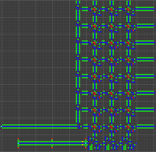
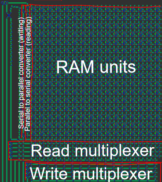
Ram
RAM has become the most difficult part of this project. It required a very specific control of each SR trigger storing data. For reading, the address is transmitted to the multiplexer and transmitted to the RAM segments. Segments of RAM in parallel display the stored data, which is converted to a sequential view and output. For recording, the address is transferred to another multiplexer, the recorded data is converted from serial to parallel form, and RAM segments distribute the signal over RAM.
Metapixels 22x22 each segment of RAM has the following structure:
By connecting all the RAM, we get something like this:
We put everything together
With the help of all these components and the general computer architecture described in Part 1, we can build a working computer!
Downloadable files:
- Ready computer for "Tetris"
- ROM creation script, empty computer and computer for finding prime numbers
Part 4: QFTASM and Cogol
Architecture Overview
In short, our computer has a 16-bit asynchronous Harvard RISC architecture. When creating a processor manually, the RISC architecture ( computer with reduced instruction set ) is a practically mandatory requirement. In our case, this means that the number of opcodes is small, and, more importantly, all instructions are processed in a very similar way.
For reference, the Wireworld computer uses the transport-triggered architecture , in which the only instruction is
MOV , and the calculations are performed by writing / reading special registers. Although this paradigm allows you to create a very simple to implement architecture, the result is on the verge of applicability: all arithmetic / logical / conditional operations require three instructions. It was obvious that we wanted to create a more understandable architecture.To keep our processor simple, while at the same time increasing its usability, we made several important decisions regarding its design:
- No registers. Each address in RAM is considered equal and can be used as an argument in any operation. In a sense, this means that all RAM can be considered registers. This means that there are no special loading / storage instructions.
- The same goes for memory allocation. Everything that can be written or read has a common unified addressing scheme. This means that the program counter (PC) is the address 0, and the only difference between the normal and control instructions is that the managers use the address 0.
- The data is sequential in transmission and parallel in storage. Due to the “electronic” nature of our computer, addition and subtraction are much easier to implement when data is transmitted sequentially in little-endian order (the least significant bit goes first). Moreover, sequential data allows you to get rid of cumbersome data buses, which are very wide and inconvenient for proper operation with time (so that the data are together, all the “bands” of the bus must have the same time delay).
- Harvard architecture, that is, there is a separation between program memory (ROM) and data memory (RAM). Although this reduces the processor's flexibility, it helps to optimize the size: the length of the program is much more than the amount of RAM we need, so we can split the program into ROM and then focus on compressing the ROM, which is much easier to do when it is read-only.
- 16-bit data width. This is the smallest power of two, which is wider than the standard field for Tetris (10 blocks). -32768 +32767 65536 . (2^8=256 , , «».)
- . (, , ), , « », . , , .
- . , , 1 (, , ) . , .
- . , . .
1.
, . .
, . «» — , «» . , - , (PC). , : , TRUE.
: «, » (
MNZ ) «, » ( MLZ ). MNZ , 1, MLZ — , 1. , . , «, » ( MEZ ) TRUE, «, » ( MGZ ) — , , 0 1.. , little-endian, endian /. .
, . , Wireworld .
— ( , ). , , , , .
,
AND , OR XOR . NOT «and-not» ( ANT ). NOT , , . ANT 1 1, — 0. NOT x ANT -1 x ( XOR -1 x ). , ANT : «» .— , . : . (- ), , «» , «». /.
— « » (
SL ), « » ( SRL ) « » ( SRA ). ( SL SRL ) ( , ). 0 15, , , . , SRA , , .. :
1.
PC . . . .
— 4 , 16 , 11 :
0000 MNZ Move if Not Zero
0001 MLZ Move if Less than Zero
0010 ADD ADDition
0011 SUB SUBtraction
0100 AND bitwise AND
0101 OR bitwise OR
0110 XOR bitwise eXclusive OR
0111 ANT bitwise And-NoT
1000 SL Shift Left
1001 SRL Shift Right Logical
1010 SRA Shift Right Arithmetic
1011 unassigned
1100 unassigned
1101 unassigned
1110 unassigned
1111 unassigned
2. ( )
(, ). .
, . , ( , PC) .
(, ), . . , , 1 , PC.
, , . PC .
3.
, , . 16 , , . 2 .
, (, ). .
. : — , , . , , .
00 : . ( )
01 : . ( )
10 : , . ( )
11 : , , . ( )
. — , , . . .
, — , , . , ( ), ( ).
4.
. , . .
, , . , , - 1 (
MNZ ), , 1 ( MLZ ). , ( ).5.
, , , .
- , PC , , PC 1 (no-op). , PC , . , , PC , .
«»
QFTASM. .
QFTASM . :
[ ] [] [1] [2] [3]; [ ], , :
MNZ [] [] [ ] – , ; [ ] [], [] .
MLZ [] [] [ ] – , ; [ ] [], [] .
ADD [1] [2] [ ] – ; [1] + [2] [ ].
SUB [1] [2] [ ] – ; [1] - [2] [ ].
AND [1] [2] [ ] – ; [1] & [] [ ].
OR [1] [2] [ ] – ; [1] | [2] [ ].
XOR [1] [2] [ ] – XOR; [1] ^ [2] [ ].
ANT [1] [2] [ ] – -; [1] & (![2]) [ ].
SL [1] [2] [ ] – ; [1] << [2] [ ].
SRL [1] [2] [ ] – ; [1] >>> [2] [ ]. .
SRA [1] [2] [ ] – ; [1] >> [2] [ ] .
, . -32768 65536. .
0 ()
1 A
2 B
3 C
Code example
:
0. MLZ -1 1 1;
1. MLZ -1 A2 3; ,
2. MLZ -1 A1 2;
3. MLZ -1 0 0;
4. ADD A2 A3 1; ,
, 1 . 28657 .
:
0. MLZ -1 5 1;
1. SUB A1 5 2; ,
2. SRL A2 1 3; 1
3. XOR A2 A3 A1; XOR
4. SUB B1 42 4; 42 (101010)
5. MNZ A4 0 0; ( != 101010),
6. ADD A1 1 1; ,
, 5. , , .
101010 , 51 56.-
El'endia Starman - . , , .
Cogol
«» , «». Cogol . «COBOL», «C of Game of Life», , Cogol C — , .
Cogol . , Cogol , :
- . ,
ADD A1 A2 3z = x + y;. . - ,
if(){},while(){}do{}while();. - ( ), «».
- . , .
( ) /, , .
:
( ) , . , , , . (,
{ , ) , . (, > = ) , , >>> == . , . — - , , , .. , . , .
( ) () .
my , , . , — . ( ) «» . . , . , , …IF-ELSEif-else C :
if (cond) {

} else {

}
QFTASM :
( )
( )
, . , .
« » , , . ,
> <= MLZ . MNZ == , , ( ). .else , , QFTASM :
( )WHILEwhile C :
while () {

}
QFTASM :
( )
( )
, , . false, . , , .
MLZ > <= . if , MNZ != , , ( ).DO-WHILEwhile do-while , do-while , . do-while , , .. , . :
my alpha[3]; #
my beta[11] = {3,2,7,8}; #
, , 15-18:
15: alpha
16: alpha[0]
17: alpha[1]
18: alpha[2]
,
alpha , alpha[0] , 15 16. alpha Cogol , .array[index] . index , . ( ) . , alpha[beta[1]] .— , , . ( ):
#
call display = fib(10).sum;
sub fib(cur,sum) {
if (cur <= 2) {
sum = 1;
return;
}
cur--;
call sum = fib(cur).sum;
cur--;
call sum += fib(cur).sum;
}
sub . , . .. , . , (). , . «» . , . . :
RAM map:
0: pc
1: display
2: scratch0
3: fib
4: scratch1
5: scratch2
6: scratch3
7: call

fib map:
0: return
1: previous_call
2: cur
3: sum
, . , . , ( ) .
,
call :call fib(10); # ,
call pointer = fib(10); #
display = pointer.sum; #
call display = fib(10).sum; #
call display += fib(10).sum; #. ( ). ( /), .
— , , : , , .
{...} Cogol . , , .Cogol QFTASM . , , . .
«» Cogol
«» Cogol, . QFTASM . : Tetris in QFTASM . ( Cogol), Cogol . , , ,
call . . , , . QFTASM 300 , , Cogol.5: ,
, Varlife «»!
Assembly
, : , , . , .
K Zhang CreateROM.py , Python Golly, . : , . , :
#0. MLZ -1 3 3;
#1. MLZ -1 7 6; preloadCallStack
#2. MLZ -1 2 1; beginDoWhile0_infinite_loop
#3. MLZ -1 1 4; beginDoWhile1_trials
#4. ADD A4 2 4;
#5. MLZ -1 A3 5; beginDoWhile2_repeated_subtraction
#6. SUB A5 A4 5;
#7. SUB 0 A5 2;
#8. MLZ A2 5 0;
#9. MLZ 0 0 0; endDoWhile2_repeated_subtraction
#10. MLZ A5 3 0;
#11. MNZ 0 0 0; endDoWhile1_trials
#12. SUB A4 A3 2;
#13. MNZ A2 15 0; beginIf3_prime_found
#14. MNZ 0 0 0;
#15. MLZ -1 A3 1; endIf3_prime_found
#16. ADD A3 2 3;
#17. MLZ -1 3 0;
#18. MLZ -1 1 4; endDoWhile0_infinite_loop
:
0000000000000001000000000000000000010011111111111111110001
0000000000000000000000000000000000110011111111111111110001
0000000000000000110000000000000000100100000000000000110010
0000000000000000010100000000000000110011111111111111110001
0000000000000000000000000000000000000000000000000000000000
0000000000000000000000000000000011110100000000000000100000
0000000000000000100100000000000000110100000000000001000011
0000000000000000000000000000000000000000000000000000000000
0000000000000000000000000000000000110100000000000001010001
0000000000000000000000000000000000000000000000000000000001
0000000000000000000000000000000001010100000000000000100001
0000000000000000100100000000000001010000000000000000000011
0000000000000001010100000000000001000100000000000001010011
0000000000000001010100000000000000110011111111111111110001
0000000000000001000000000000000000100100000000000001000010
0000000000000001000000000000000000010011111111111111110001
0000000000000000010000000000000000100011111111111111110001
0000000000000001100000000000000001110011111111111111110001
0000000000000000110000000000000000110011111111111111110001
Varlife :
, Varlife. …
«»
«». «». , Varlife OTCA- . Varlife «».
, Golly ( metafier.py ), OTCA- «». , , Varlife. , Varlife .
, ( «») 1 436 x 5 082. 7 297 752 6 075 811 , 1 221 941 . OTCA-, 2048 x 2048 , 64 691 ( «») 23 920 ( «»). , 2 940 928 x 10 407 936 ( ) 29 228 828 720 79 048 585 231. 1 27-74 .
, , .
kill metafier. 10 ( gzip RLE), . , . Golly RLE, , — .K Zhang metafier , MacroCell, , RLE. ( , metafier), (121 1,7 ), , . , MacroCell . Varlife.
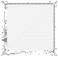
«» .
, «», , ? Nothing like this. , :
- muddyfish Kritixi Lithos , QFTASM.
- El'endia Starman - QFTASM.
- quartata GCC-, GCC C C++ ( , , Fortran, D Objective-C) QFTASM. , .
- , , , , - (PIC) (.. ). PIC , . PIC.
- , QFT. Pong.
6: QFTASM
Cogol «», .
2016 . - , , .
Python , , .
QFTASM : , , .
Python , .
, (
#include )..
XML, .
, . , .
, , ,
sub generic_variables , .. ,
assign(a, 12) call_subroutine(is_prime, call_variable=12, return_variable=temp_var) . , . operator , , , , + % . , — , ., . :
operator(int a + int b) -> int c
return __ADD__(a, b)
int i = 3+3
turns into
int i = __ADD__(3, 3), . «»
unsafe , .(scratch variable)
a += (b + c) * 4 . , :scratch_1 = b + c
scratch_1 = scratch_1 * 4
a = a + scratch_1, . . . .
VariableStore . , .
( )


...
, —
sub , call_sub , return , assign , if while . , QFTASM.sub
. ,
main ( ).if while
while if : . while ,...
:
...call_sub return
, , , . , . . , .
, . . . .
return , . .assign
: :
MLZ -1 VALUE VARIABLE, . , . , , , .
, .
#include stdint

sub main
int a = 8
int b = 12
int c = a * b
, . ,
a = 8 , b = 12 , c = 96 . stdint.txt :operator (int a + int b) -> int
return __ADD__(a, b)
operator (int a - int b) -> int
return __SUB__(a, b)
operator (int a < int b) -> bool
bool rtn = 0
rtn = __MLZ__(ab, 1)
return rtn
unsafe operator (int a * int b) -> int
int rtn = 0
for (int i = 0; i < b; i+=1)
rtn += a
return rtn
sub main
int a = 8
int b = 12
int c = a * b, . , . -
NAME NAME operator
LPAR OP (
NAME NAME int
NAME NAME a
PLUS OP +
NAME NAME int
NAME NAME b
RPAR OP )
OP OP ->
NAME NAME int
NEWLINE NEWLINE
INDENT INDENT
NAME NAME return
NAME NAME __ADD__
LPAR OP (
NAME NAME a
COMMA OP ,
NAME NAME b
RPAR OP )
...
, . .
GrammarTree file
'stmts': [GrammarTree stmts_0
'_block_name': 'inline'
'inline': GrammarTree inline
'_block_name': 'two_op'
'type_var': GrammarTree type_var
'_block_name': 'type'
'type': 'int'
'name': 'a'
'_global': False

'operator': GrammarTree operator
'_block_name': '+'

'type_var_2': GrammarTree type_var
'_block_name': 'type'
'type': 'int'
'name': 'b'
'_global': False
'rtn_type': 'int'
'stmts': GrammarTree stmts
...
. . , . .
('sub', 'start', 'main')
('assign', int main_a, 8)
('assign', int main_b, 12)
('assign', int op(*:rtn), 0)
('assign', int op(*:i), 0)
('assign', global bool scratch_2, 0)
('call_sub', '__SUB__', [int op(*:i), int main_b], global int scratch_3)
('call_sub', '__MLZ__', [global int scratch_3, 1], global bool scratch_2)
('while', 'start', 1, 'for')
('call_sub', '__ADD__', [int op(*:rtn), int main_a], int op(*:rtn))
('call_sub', '__ADD__', [int op(*:i), 1], int op(*:i))
('assign', global bool scratch_2, 0)
('call_sub', '__SUB__', [int op(*:i), int main_b], global int scratch_3)
('call_sub', '__MLZ__', [global int scratch_3, 1], global bool scratch_2)
('while', 'end', 1, global bool scratch_2)
('assign', int main_c, int op(*:rtn))
('sub', 'end', 'main')
QFTASM. :
int program_counter
int op(*:i)
int main_a
int op(*:rtn)
int main_c
int main_b
global int scratch_1
global bool scratch_2
global int scratch_3
global int scratch_4
global int <result>
global int <stack>
. , , QFTASM.
0. MLZ 0 0 0;
1. MLZ -1 12 11;
2. MLZ -1 8 2;
3. MLZ -1 12 5;
4. MLZ -1 0 3;
5. MLZ -1 0 1;
6. MLZ -1 0 7;
7. SUB A1 A5 8;
8. MLZ A8 1 7;
9. MLZ -1 15 0;
10. MLZ 0 0 0;
11. ADD A3 A2 3;
12. ADD A1 1 1;
13. MLZ -1 0 7;
14. SUB A1 A5 8;
15. MLZ A8 1 7;
16. MNZ A7 10 0;
17. MLZ 0 0 0;
18. MLZ -1 A3 4;
19. MLZ -1 -2 0;
20. MLZ 0 0 0;
Syntax
, , . Python, . , .
main , main() C- . ., .
int bool , .stdint.txt , . , . #include stdint . stdint , + , >> * % , QFTASM., QFTASM
__OPCODENAME__ .stdintoperator (int a + int b) -> int
return __ADD__(a, b),
+ , int .Source: https://habr.com/ru/post/338584/
All Articles