Networks for the harshest. Part thirteen. MPLS Traffic Engineering
Modern computer networks, offering cheap traffic, high profit, superstability and divine convergence, have lost such attractive qualities of old technologies as the ability to determine the path of traffic and ensure the quality of the channel from beginning to end.
However, the network linkmeup has grown to the size of the federal operator. The ability to manage traffic and quickly restore services has become a very important requirement in the MPLS network.
It's time to implement Traffic Engineering.
')
Why do you need traffic engineering at all?
I will give a simple example.
Convergent network of mobile operator.

Two types of traffic:
The left shoulder is a wide 10G optical channel. Right - reserve through a leased line - 1G.
The total traffic volume is 2.5 Gb / s, mobile: 800 Mb / s.
In the event of a break of the main channel, you need to switch to the backup only mobile traffic and do it in 50ms.
Think, can we do it by standard means? Of course, we can divide traffic of different services by different VPNs, but send them by different routes - no.
Without the use of TE, all traffic will be redirected to the right shoulder, and there, who could have imagined that there is not enough bandwidth, drops will begin.
In addition, the convergence rate of OSPF or ISIS, even when using BFD, amounts to tens of ms, but after that the transport LSPs must also be reconfigured. Nowadays, it will not pass unnoticed by subscribers.
What are the traffic management functions provided by MPLS Traffic Engineering?
The basic mechanisms for the operation of MPLS TE were discussed in the release of SDSM 10 , where I send you for detailed consideration. And here is a brief summary.
In terms of data transmission, TE is slightly different from LDP. Bold highlights:
But in terms of management, the differences are much more significant. C them the rest of the way and we will understand.
And his place is taken by RSVP-TE - the successor of the RSVP protocol rejected by the TCP / IP stack.
TE works in close symbiosis with IGP. Although it is more correct to call it parasitism. He forces them (OSPF or IS-IS) to serve themselves: to transfer the information he needs and thereby fill TEDB.
The process is as follows:
All this in detail and in colors in the article 10 . And there is the simplest example in practice.
Next we will beat around the bush of this scheme:
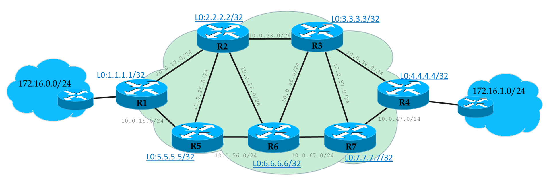
We have a L3VPN client whose offices are connected to Linkmeup_R1 and Linkmeup_R4.
Unlike LDP LSP, which traffic runs by default and so on, we need to send traffic to TE tunnels.
And there are for this the following ways:
The easiest to understand and the most difficult to maintain.
Essentially the same static route.
This method is the most common and is supported by almost all manufacturers.
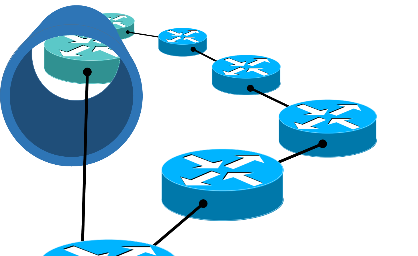
The router treats the tunnel as a virtual interface. And through this interface, remote routers seem to be directly connected to the local one, and not in dozens of hopes. A sort of telecommunication wormhole. It is called - shortcut - shortened path.

Flamm's Wormhole
But the default IGP protocols do not want to see this and use the physical interface to send traffic.
With the help of IGP Shortcut (in AutoRoute Announce cisarea), we force the routing protocol on the Ingress LSR to treat the tunnel as a normal line — the Egress LSR is supposedly connected directly. And accordingly, all networks located behind the Egress LSR will be accessible through the tunnel.
Thus, all whose destination point this router, or nodes behind it, will be sent to the tunnel. Including VPN packages.
Thus, the tunnel becomes a common interface, and, like any other interface, it must have a metric.
First , there are two types of metrics:
IGP metric is a well-known interface metric from the basic routing course.
TE metric is the metric that will be used when calculating the TE tunnel metric.
Secondly , we have the following methods for managing the tunnel metric:
* This method depends on the manufacturer - someone has, someone does not.
Tunnel-policy is used to redirect VPN traffic exclusively to tunnels.
That is, in the VPN configuration mode (whether L2 or L3 is important), it is indicated which tunnel should be used.
There are two possibilities:
The juna often has its own approach (see for yourself today). So it has several routing tables:
When placing VPN routes into an IP routing table, BGP is checked against the inet.3 MPLS table. If in it he finds the LSP before the Next Hop of the VPN route, then the traffic is automatically driven into that LSP. No additional action is required.
This is in a sense similar to the mix Tunnel-Policy and IGP Shortcut, only automatically.

All the same network, but with bandwidth limitations.
We need to provide L3VPN to the client.
The client has requirements: 8 Mb / s. Take out and put it down.
We direct traffic to the tunnel through Auto-Route.
So let's start with the fact that no LDP - only RSVP-TE. That is, there is no LSP until we configure the tunnel.
Although we already did all this last time, but we will start the setup from the beginning.
Now the path from R1 to R4 looks like this: R1-> R5-> R2-> R6-> R3- > R4 - all because of these damn restrictions.
Now we start messing around.
Let's try to break our working link R3-> R4, while continuous ping lasts.

LSP changed to R1-> R5-> R2-> R6-> R3-> R7-> R4 with the loss of one packet. This time can increase significantly if there is no physical line drop on the routers.
For example, turn off the R2-R5 line and observe the fall of the TE tunnel on R1 without further restoring it.
If the link R3-> R4 is restored, will the tunnel be rebuilt?
Yes. But not soon. Fly many packets before Ingress PE shifts its RSVP. ( Actually depends on the manufacturer )
This is called Tunnel reoptimization. At some intervals, Ingress PE causes the CSPF to check whether more optimal routes have appeared.
That is, first he builds a new RSVP LSP, lets traffic go in there and only then breaks the old one. This mechanism is called Make-Before-Break, about which at the end.
So, we have enough ways to influence the traffic path with TE:
The first most obvious method is interface metrics.
As we remember, there are IGP-metrics, and there are TE-metrics. The second ones are by default the first.
TE metrics on link interfaces not only affect the tunnel metric in terms of IGP Shortcut, but are also taken into account when building LSPs.
To tell the tunnel which metric to consider:
Default value:
Concrete tunnel:
Cisco in detail about metrics .
In practice, we got acquainted with the basic function of TE - the ability to build MPLS tunnels with reservation of resources throughout the entire LSP.
But does this idea with Bandwidth bother you? Do not we return to the stone age, when there was no re-subscription. Yes, and how do you determine the magnitude of this limit? And what to do with the fact that it floats on the order of the day?
The method when we adjust the static value of the required band is called Offline Bandwidth.
The idea is that there is a certain program costing three in the Patriarch's Ponds, which, according to some algorithms, calculates one figure for your traffic, which you need to configure in the tunnel.
The band can be configured for the entire tunnel, as we did in practice above:
And it is possible for a specific RSVP LSP:
This value may differ from what is specified for the tunnel and has a higher priority.
At the same time, for another LSP (path-option 2, for example), the value may differ - they say, if you cannot reserve 8 Mb / s, let's try at least 5?
Offline Bandwidth has two significant drawbacks:
- Handwork, which a good engineer tries to avoid.
- Non-optimal use of resources. Well, we will assign a 300 Mb / s band to the client, reserve it on each line, but in fact it needs something from the power of 30. And only at the peak, when the database is backed up, you need 300. Inaccurately.
This option was practiced at the dawn of TE. He exists now.
However, keeping up with the times, you need to be more flexible and pliable.
And Autobandwidth is great.
This mechanism tracks the loading of the tunnel for a certain period and then adapts the reservation.
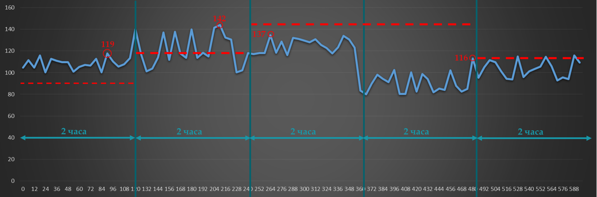
For example, Adjust Interval we have 2 hours. The current value of the reserved bandwidth is 90 Mb / s.
Adjust Threshold - 20 Mb / s.
In the first interval, a burst of 119 Mb / s (up to 119 Mb / s) is greater than the threshold. So RSVP-TE is trying to build a new tunnel with new values for bandwidth.
In the second - 23 Mb / s (up to 142) - again more than the threshold. Update reservations whenever possible.
In the third, the maximum value drops to 137 Mb / s - the difference is only 5. Nothing happens.
In the fourth burst drops to 116 (a difference of 21) - RSVP signals the new LSP with reduced bandwidth requirements.
So, every two hours there will be a check and, possibly, a rebuilding of the tunnels.
The shorter the Adjust Interval, the more consequently the reservations will be updated and the more efficiently used available bandwidth.
Something like this at the two-hour interval will look like the 24-hour auto-bandwidth behavior.

Already noticed the problem?
Take the typical profile of morning traffic:

And such rubbish all day.
Here we measured at 8 am splash - 200 Mb / s. And for two hours this value is kept for the tunnel. And during this time, people have already come to work and launched YouTube - the average speed is already 240, and the bursts are up to 300. Until 10 am, there will be a quiet degradation. Silent, because neither the tunnel nor the Auto-Bandwidth know about it. But users know and their ITshnik also knows, believe me.
If, however, the adjustment interval is greatly reduced, then new LSPs will be constantly resigned to the network.
To solve this and other problems, there are mechanisms Overflow and Underflow . The first is for tracking the growth of traffic, the second is for the decrease.
If the difference between current redundancy and traffic surges exceeds the Overflow threshold several times in a row, RSVP TE will try to build a new LSP without waiting for the Adjust Interval to expire.
The same is true for Underflow - RSVP-TE will reregenerate LSPs with lower requirements if they notice a tendency to decrease traffic volume.
And there is only one, but a serious problem.
This is how our world works, that when traffic grows from one subscriber, it usually grows from another. And it may be that when the time comes to increase the reservation again, it will have nowhere to increase it - everything is taken. And then, if there are no other ways that meet the new conditions, the old one will be used. And no one will care that there is not enough of it, that the packages have started to get lost, that the client is looking for the director’s number in order to find an engineer who can be torn off something superfluous.
We will deal with this with the help of tunnel prioritization, which is described below.
To enable the AutoBandwidth function globally and at the same time the Adjust Interval settings:
Next, for each tunnel separately, you need to activate AutoBandwidth. You can also set a different value for the Adjust Interval, as well as set the minimum and maximum possible values for the reserved band.
To configure overflow:
Read more about Auto-Bandwidth in a very honest document .
This is the mechanism that prioritizes tunnels: which one is more important. It is applicable, as for the case of Auto-Bandwidth in particular, and for any construction of RSVP LSP in general.
Everything is very logical:
Setup Priority - the priority of installing RSVP LSP.
Hold Priority - the priority of holding RSVP LSP.
If there is not enough bandwidth on the node, and the new tunnel has a higher installation priority than the old one’s retention priority, a new one will be built - the old one is broken.
Both have 8 values: from 0 to 7. For both, 0 is the highest, 7 is the lowest.
For example, we have a LSP1 tunnel that has Hold priority 4 .
Here comes a request from RSVP-TE on LSP2 with Setup Priority 6 and Hold Priority too6 . If there is enough bandwidth, then it’s just built. If not, then the router will not allow this, because the existing tunnel is more priority than the new one (4> 6).
Suppose there are enough lanes and both tunnels went up normally.
And here comes a new request for LSP3 with Setup / Hold Priority 5 . This is higher than that of LSP2, but lower than that of LSP1. And he already lacks the band. LSP1 will definitely not be touched, because its Hold priority is still the highest. And then there are two options:
Regarding the values, they are usually chosen the same for Setup and Hold. And you should not configure Hold lower than Setup. Firstly, this is not logical. Secondly, a situation may occur when two tunnels enter a loop, when they constantly overwork each other — once one is established, the second will break it and build itself, then the first will break the second and so on.
There are two tunnel replacement modes:
Hard preemption — A higher priority LSP simply replaces a low priority LSP. Even if a low priority LSP then finds a new path, some of the traffic will be lost.
Soft preemption- The Make-Before-Break mechanism is used. A router via RSVP-TE tells the Ingress LSR of a low-priority LSP to look for a new path. A high priority LSP waits until low-priority LSP traffic switches to the new LSP.
In this case, if the path could not be found for some time, the low-priority LSP still breaks and the high-priority one is built.
Replacement priority data is transferred to the RSVP-TE PATH and is taken into account when reserving resources at intermediate nodes.
If you noticed, after configuring tunnel mpls traffic-eng badnwidth on the tunnel interface, the line tunnel mpls traffic-eng priority 7 7 automatically appears in the configuration .
The fact is that without bandwidth requirements, priorities have no meaning — you can build as many tunnels as you want through a single node - after all, the band is not reserved - and there is no command.
But, as soon as the demand appeared, along the way, priorities begin to play a role.
7 is the default value — the smallest.
Let's set up a new tunnel on Linkmeup_R1 to 4.4.4.4 with a higher priority?
The required band is only 4 Mb / s. Therefore, the tunnel must pass along the path R1-> R2-> R3-> R4.
That's

right , here is his trace: With Tunnel4, they have only one common link R3-> R4, but its bandwidth is only 10. And two tunnels need 8 + 4 = 12.
Tunnel42 with installation priority 4 squeezes Tunnel4 with retention priority 7.
And you have to look for a new path.
And it is located:

First, the old RSVP LSP Tunnel4 is removed and a new one is signaled according to the available path.

Then RSVP-TE signals the LSP for Tunnel42.


At this point, back to Autobandwidth. A bunch of Tunnel priority + Autobandwidth gives an elegant solution.
One early morning there was little traffic, autobandwidth calculated exactly how much it was in each tunnel, and TE had enough bandwidth everywhere.
Then closer to dinner traffic grew, autobandwidth adapted, re-reserved new bands - still enough.
One evening, one by one, the tunnels begin to fly out, because TE cannot reserve a new lane.
And here it is important that the tunnels of fat clients, IP-telephony and the channel for the Ministry of Internal Affairs never fall. Then we set Hold priority for these tunnels higher than the others.
- If you try to reserve a low-priority band on the interface, where it is not enough, it will break off.
- High priority, on the contrary, will crowd out the low-priority one and occupy the vacant strip.
Turns out that
The idea of Explicit-Path was more than fully disclosed in the 10th edition of the SDSM .
As you remember, CSPF calculates the shortest path based on constraints. Further, this path is transformed into an ERO object (Explicit Route Object) of the RSVP-TE PATH message, which explicitly states which path this PATH should be passed on.
So if you want some nodes to be present or vice versa absent in this path, you can explicitly specify this in the Explicit-Path, which will be one of the input constraints for the CSPF.
So, we manually specify which nodes the LSP should go through, and which ones should not.
RSVP-TE asks CSPF to calculate the route taking into account the Explicit-Path and other tunnel constraints.
If one is at odds with the other - trouble, there will be no LSP.
1) Creating the most explicit-path with constraints:
2) Applying it to path-option on the tunnel:
SRLG - Shared Risk Link Group . Another way to influence the LSP and a great idea against flat rings .
The task of this function is to prevent the construction of the main and backup LSPs through lines that can be damaged at the same time.
For example, two fibers that physically pass in the same cable will most likely be torn by the same excavator bucket.
An SRLG group is a group of interfaces that "share the risk." ABOUT!Risk group.
Manually (of course, and how else would the router know that these are physically identical lines ) are configured interfaces that are members of one SRLG group.
Information about SRLG is distributed over the network along with IGP announcements, as is the available band or Attribute-Flag value, and is then placed in TEDB.
The CSPF should then take this information into account when calculating the shortest routes.
There are two modes:
Force Mode forces the CSPF to take into account SRLG data - if there is no other way, then the backup LSP will not be built at all.
Preffered Mode allows the construction of spare tunnels via SRLG lines, if there are no other possibilities.
The mode is set on the Ingress LSR.
To add interfaces to one risk group, the following command is entered on any nodes:
And on Ingress PE enable the SRLG check:
What is this team, let's talk in the FRR section.
It should be scary right now. I'm scared.
So, by this moment we learned about four traffic management tools:
RFC3630 for OSPF, and for ISIS, define the TLV for the Administrative Group, which is transmitted by the IGP along with other characteristics of the lines.
But the new bundle is an amazing rescue that will solve all our problems, just click the “do well” button.
The idea is that we mark each interface with certain colors.
And then we say that this tunnel can go along the red and purple lines, but it cannot go along the green, yellow and brown.
Marketing Bullshit! Unclear? Me too.
So.
The Administrative Group (for Juniper: admin-group, for Cisco: Attribute-Flag) is an attribute of the physical interface that can describe its 32 discrete characteristics.
Which bit of 32 for which the operator decides is responsible.
Since we have examples in the Cisco console, then I will use the term Attribute-Flag along with the Administrative group, which is not entirely correct.
Affinity and mask are tunnel requirements for their path.
What kind of relationship can be formed in this triangle {Affinity, Mask, Attribute-Flag}?
If this equality holds, the tunnel can be built through this interface.
Consider an example.
We have 32 bits and a policy - for which each of them is responsible (take the example above).
In Mask, we indicate what characteristics of the channel we are interested in. For example, for a 2G tunnel it’s important
Therefore, we put 1 in the mask where it’s important what it is:
Mask: 0100 0110
Took only the first 8 bits for simplicity.
Note that this is Wildcard Mask .

In Affinity, we specify what we need.
Affinity: 0000 0100. Perform the

operation and we get: 0000 0100.

Now let's take three interfaces for example.
That is, when building the LSP, the value of Attribute-Flag will be taken into account on each link.
The default Attribute-Flag value on the interface is 0x0 . And in a sense - it is regrettable - because the result of the operation “And” with a mask will differ from the result with Affinity, which means we must configure Attribute-Flag on all interfaces.
Accordingly, within the company, policies can be developed, how to tag interfaces, and how to manage traffic. You can even assign this task to the control system so that the work of the engineer can be reduced to placing ticks in the graphical interface, and the configuration would then be applied automatically.
But in any case, this does not detract from the human factor on the one hand, and simply the incomprehensible complexity of debugging and maintenance on the other.
However, there have been cases of the integrated implementation of the Administrative Group even on the networks of Russian operators.
Other examples of use could be regional or country codes. Then it would be possible to ask through what geography to pass traffic.
In this light, 32 bits is very small, so RFC 7308 defines extended administrative groups, the number of bits in which is limited by the natural limit of LSA or MTU in general.
The guy on the fingers chews Affinity and folds it in a pile with his mouth.
Very very short. Just see what works. Short because Affinity requires Attribute-Flag configuration on all nodes and all interfaces. And this is what the last thing you want, to be honest.

We continue with the last configuration, where we have two tunnels.
Configuration file.
Tunnel42 follows the path R1-R2-R3-R4. With him and play.
The default Attribute-Flag is 0x0. Therefore, we take it as Affinity - that is, all the interfaces we have under the condition. In addition to R3-R4, on which we configure Attribute-Flag 0x1. Since the equality will not be fulfilled - the CSPF will not be able to build the shortest path through this link.
And we observe how the tunnel went around this link.

However, Tunnel4 fell apart safely. The default Affinity value is also 0x0, but the mask is 0xFFFF. Therefore, he also did not fit into the reconfigured link R3-R4.
But, we could adjust the mask 0x0 on it - ignore any Affinity and Attribute-Flag bits:
And then the tunnel will rise, not taking into account these restrictions.
In practice, we have already seen that rebuilding a tunnel in the event of a breakdown takes several seconds. Well, it was not so bad at the time of my grandfather.
The whole history of the development of computer networks is the story of the fight against accidents, the struggle for the speed of convergence, for the reduction of the break time.
What do we have in service?
IP is good, but converges in seconds, or even minutes.
MPLS TE offers two options to increase stability and reduce service interruption time.

The first implements protection at the level of the entire LSP, the second at the level of a link or node - and it is called FRR - Fast ReRoute.
When setting up a tunnel, we can specify how many and which LSPs we want to build.

Protection is not only and not so much about the restoration of the service, as about the speed of this recovery.
In this vein, it is clear that non-standby is not the case. Based on IGP, RSVP-TE first waits for updating the routing information, then it has to work out itself - the count for seconds. The signal is a notification from RSVP-TE or BFD that the LSP is no longer live, or the information from the IGP about the topology change.
For the Standby case, the primary RSVP LSP and the standby are built simultaneously. Accordingly, as soon as the Ingress LSR fixes the gap ofthe main LSP pattern , the traffic immediately switches to the spare one - we are threatened with losing only those packets that were sent exactly before the accident was detected.
But the FRR - Fast Reroute - allows you to save even those cars that are already now striving for the purpose, not even knowing that the bridge has collapsed there. That is, FRR is like a detour on the section of the road where repairs are underway, and Backup LSP is another route.
FRR uses workarounds and is described in RFC4090. The average switching time after detection of an accident is 50ms.
This is a thing that just turns on, and then it works automatically. That is, from the point of view of configuration, it looks elementary.
As is usually the case, things that are simply customized, hide something interesting under a coat.
So, FRR has two functions:
Therefore, it is called Local Protection - it does not monitor the entire LSP, but only checks the availability of the nearest link or node.

When terrible happens, it simply takes the packets to the bypass tunnel.

Figure a) shows line protection. On b) - protection of nodes.
Take LSP from R1 to R4. Each node along the path, except R4, will try to build its own workarounds.
So R1 to protect the line R1-R2 will choose the path R1-> R5-> R2. And to protect against the fall of the node R2: R1-> R5-> R6-> R3.
R2 must protect line R2-R3 and node R3.
ETC.
The task of FRR is to save those bags that fly directly into the abyss of the collapsed link, leading them to this very Bypass LSP.
When the PLR notices that the line through which the transit LSP lies has fallen, it instantly redirects traffic. Note that it is not Ingress PE that does this, but the node where the break occurred. A link drop is fixed by a drop in an interface or a BFD session.
You can compare the FRR with the arrow on the track.
To redirect packets so quickly, the Bypass LSP must be built in advance. This is what happens.
Each node in the course of Primary LSP is looking for how to get around the fall of the next link and the fall of the next hop.
That is, it launches the full LSP engine:
Tunnels are built automatically and are not displayed in the configuration. But otherwise, these are ordinary tunnels, through which you can view information or trace them.
- how to put packets from Primary LSP into this Bypass LSP.
- How on MP to understand what to do with the received happiness.
Everything is very simple - FRR LSP is a regular tunnel. That is, it is enough for us to tunnel our previous tunnel in the section from PLR to MP, which means add one more MPLS tag to each packet. There will be 3 of them: VPN, Tunnel, FRR.
So, when a packet arrives at the PLR at the time of the crash, it first does the usual external label SWAP, as if it should go through the old (currently broken interface) and he also knows that you need to transfer it to the FRR tunnel - adds another tag
Next, the packet is switched by Bypass LSP according to standard rules - the external (FRR) label changes, and the two internal ones remain unchanged.
On the last but one node, the external label is removed - PHP and before the MP the package comes with the original two.
MP receives the packet, looks at the transport label and then commutes the packet, as if nothing happened.


Everything is absolutely the same except for the transport tag - PLR should know what label the NNHOP is waiting for.
The tunnel is now not built to the next node, but through one - NNHOP. This is assisted by the attribute of the RSVP message - LRO (Label Request Object). Being in the RSVP PATH, he asks the nodes to highlight tags along the way.
And in the RSVP RESV Label Object contains these same highlighted tags.


When signaling Bypass LSP, the question arises: whether to reserve resources.
If yes, then it is already called Bandwidth Protection.
In this case, it usually does not make sense to reserve resources twice for the same tunnel. Well, really - from the fact that we have taken the traffic from Primary to Bypass, it does not follow that the resources will be used twice on PLR and MP? Moreover, the free line may not be enough. Therefore, the concept of SE (Shared Explicit) is introduced. If this attribute is set in the original RSVP PATH, resources will not be backed up twice - intermediate nodes will know that this is not a completely independent LSP - this is the old idea of something.
So, the procedure is as follows:
FRR Modes.
The only question that still needs to be discussed about FRR is which LSPs should be redirected? He is not the only one who probably goes through this PLR?
There are two options:
The first option is preferred because it uses resources more efficiently. All that was above about the Facility mode .
One-to-One introduces a couple of new terms:
Detour LSP - spare tunnel . Same Backup LSP, but Detour protects only one Primary LSP,
DMP - Detour Merge Point - Same MP.
This method is very similar to Facility, but there is one significant difference. In Facility mode, the existing LSPs were tunneled into the Bypass LSP, getting the third label on the stack. In the One-to-One mode, when you go around an obstacle, two labels will remain in the stack, that is, it will look and work like the most common LSP.
PLR when a crash is detected, the received packets of the old LSPs will be sent in a new way, simply by performing the usual Swap transport tag. But the label and output interface will be new - from the Detour LSP.
DMP also performs a normal swap transport label. Instead of the Detour LSP tag, it substitutes the old one from the Primary LSP and sends it further.


I disassembled the Facility mode in detail, because it is the most commonly used.

We continue with the same network from the point at which we stopped (except for affinity).
Configuration file.
Add Standby LSP with lower bandwidth requirements: 3 Mb / s.

The path of the protective tunnel was laid down as follows:

First, on the R1-R2 line, 4 Mb / s out of 5 already occupied Tunnel42. Therefore, there is no band left for the spare LSP Tunnel4.
Secondly, the primary and backup LSPs usually use the Shared Explicit (SE) bandwidth reservation method, which means that there will not be a bandwidth reserved for the same tunnel twice. Therefore, through 10 Mb / s, the link R1-R5 managed to lay both the main LSP (8 Mb / s) and the backup (3 Mb / s).
Thirdly, you can see that the backup LSP on the R6-R4 segment has chosen the same path as the main one. Therefore, the use of Explicit-path can sometimes be quite justified.
For pleasure and satisfaction, you can pull the link R2-R5 and make sure that the traffic of subscribers is almost not interrupted.
1) Turn on FRR on the tunnel
It is logical to do this at the other end
Right after that, RSVP signaled a new attribute along the LSP.

He said that link protection was needed for this LSP.
But the tunnels do not appear yet.
2) Now you need to enable the ability to build tunnels automatically:
What does this team do? Checks which interfaces are used for tunnels that require Local-protection, and tries to protect the link and the next node, so on each node (where it can) it builds the necessary tunnels.
For example, on Linkmeup_R2 would be 4:

Please note that protection tunnels are built without any bandwidth accounting, until this is discussed separately.

So, now I want to break the line R2-> R6.
In theory, to protect this line, we have Tunnel65436 (R2-> R5-> R6). But then the full path will look a little strange: R1-> R5-> R2-> R5 -> R6-R3-> R4 - that is, along the R5-R2 line, the traffic will pass twice - back and forth. Therefore, R2 briefly turns on the intellect and selects Tunnel65437, which directly leads to R3.
Then on section R2-R3 we should see two labels in the stack - VPN and tunnel. The bypass tag will not be inserted because PHP.
If you want to see all three tags, to make sure that the FRR is working, enter the command to R2
R2 .
We look at the VPN and transport labels R1:


PUSH VPN - 16
PUSH Tunnel - 26
We look at the table of labels on R5:

SWAP Tunnel 26-> 16
We look FRR on R2:


SWAP Tunnel 16-> 27 (label that is waiting for NHOP)
PUSH Bypass Implicit Null - that is, the label is not really inserted.
Tags on R3:

PHP: POP Tunnel 27 (wait).
We look at the dump on the site - 2 tags (implicit null was not really added):

Perfectly!
And finally, a couple of light topics without practice.
A separate issue will be dedicated to QoS. Get ready. But not to talk a little about it now would be unforgivable.
So MPLS TE uses the IntServ QoS paradigm - pre-reservation of resources all the way.
That is, we are initially confident that the necessary band (and other requirements) will be provided to the service. In this case, the packets inside the tunnel (LSP) are all equivalent.
However, it happens that the client traffic grows. Maybe at some point its volume exceeds the static threshold, and there is no longer a free band, or Autobandwidth has not yet managed to work out the speed increase.
One way or another, packets are beginning to be discarded, and without any parsing whether they are important or not.
That is, the idea of IntServ in the MPLS TE implementation by itself does not guarantee that there will be no problems on every single node.
And who is responsible for Per-Hop Behavior? Remind me? DiffServ? And if we do not combine these two beautiful paradigms?
Indeed, in the MPLS header there is an EXP field, which was planned to be an Expeditional, but it has long been officially used to set the priority of packets and is called the Traffic class. That's just the old habit of it and now continue to call EXP,
This is called MPLS DiffServ-aware Traffic Engineering - MPLS DS-TE.
The idea, generally speaking, is to provide MPLS-packages with the quality of service expected by the original packages. That is, ideally, it is necessary to make a 1 to 1 correspondence. But EXP is only 3 bits, that is, 8 priority values, while DSCP is 6 bits (64 values), whatever one may say, but the details with such archiving are lost.
Thus, there are two approaches:
E-LSP - EXP-Inferred LSP . To score and rejoice at what we have.
L-LSP - Label-Inferred LSP . Encode priority with EXP + tag.
For the case when we initially deal with the DSCP field, we transfer only the three most significant (left) bits of the DSCP to MPLS EXP.
And yes, we accept the loss of detail.
When the PDU arrives at the Ingress LSR, we place it in the tunnel and set the priority in the EXP field.
Well, for example, in one tunnel we will have the data of broadband access and fixed telephony. Naturally, we will give priority to telephony 5, and everything else to 0.
Then even if a traffic jam occurs within one tunnel, the weak will die first.
In this case, the QoS data is encoded into a bunch of Tag + EXP. It is assumed that the label specifies the processing mechanism in the queues, and the label - the priority of packet drop.
PHB information must be signaled during the installation of the LSP.
Each L-LSP carries only one type of service.
Today, operators for the most part define four traffic classes: BE, AF, EF and CS. E-LSP is more than enough for this, so L-LSP is not only practically not used, but moreover, not all vendors have it. Therefore, I will not dwell further on the comparison of methods.
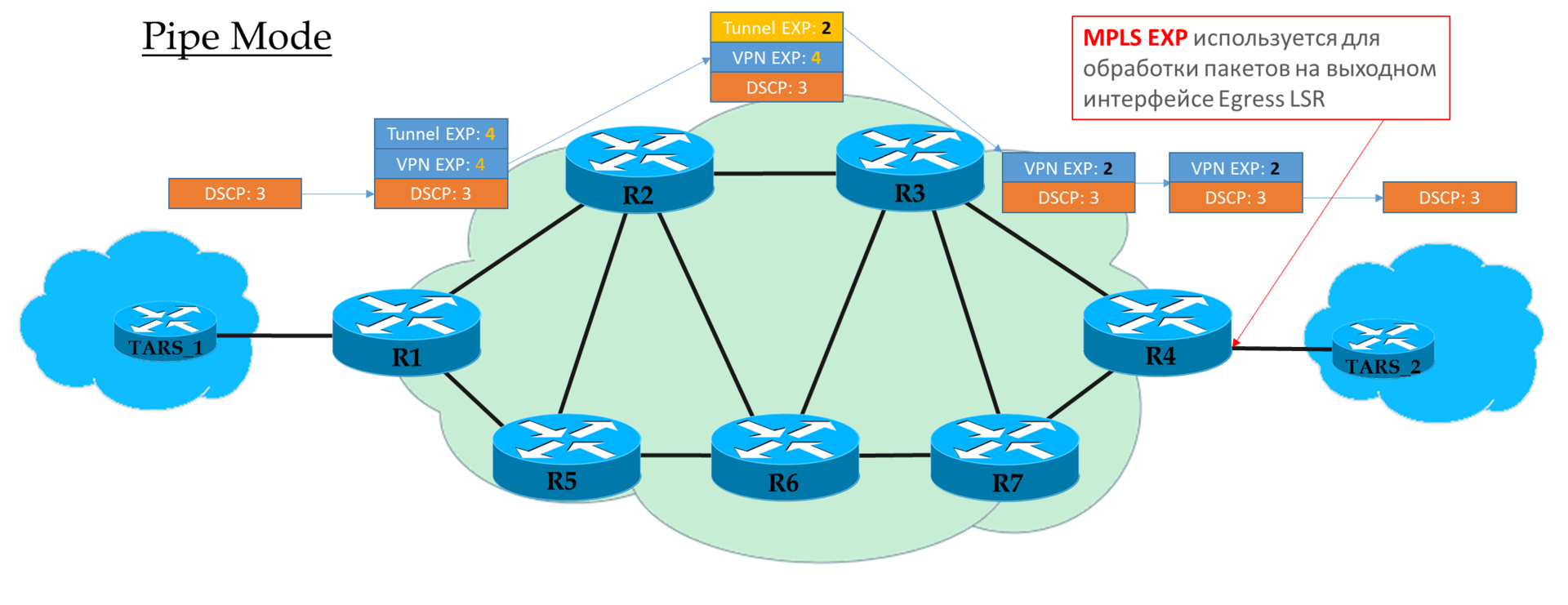
But what is interesting is what CoS field to trust on each node: IP DSCP, Tunnel EXP or VPN EXP?
There are three modes:
Remember, already faced with such concepts when parsing TTL in MPLS L3VPN ? Something similar here.
End-to-End.
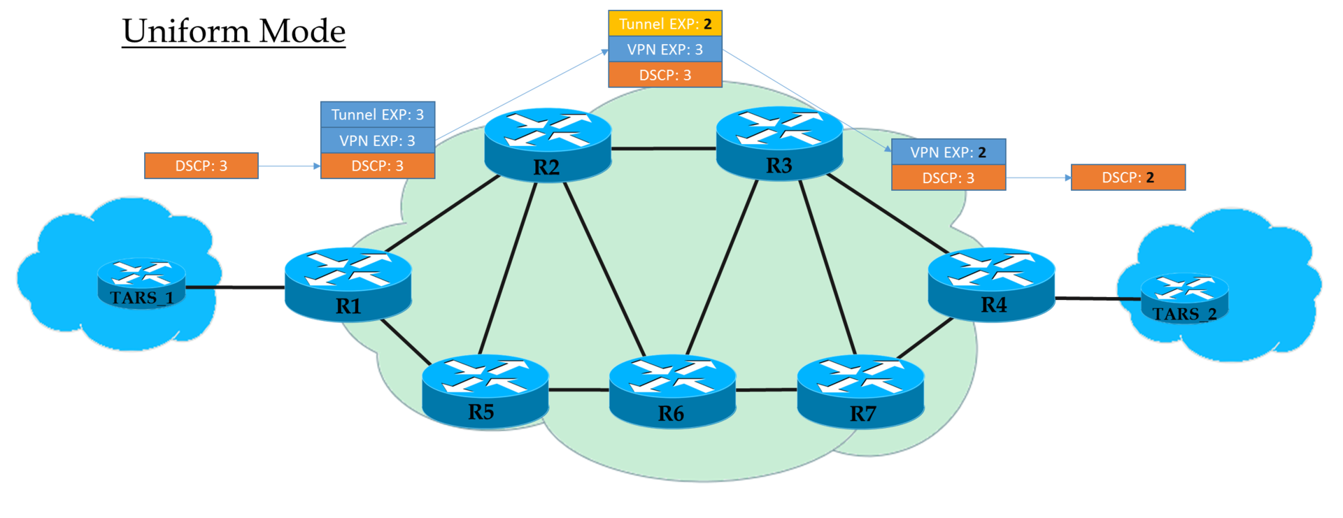
Ingress PE IP DSCP ( , , «» ) MPLS EXP ( , VPN ). Ingress PE EXP MPLS.
P EXP. , .
(PHP) EXP VPN-. , — Uniform, .
Egress PE VPN, EXP IP DSCP, .
That is, if somewhere in the middle the value of the EXP tag in the tunnel header has changed, then this change will be inherited by the IP packet.
If, on Ingress PE, we decided not to trust the DSCP value, then the EXP value that the operator wishes is inserted into the MPLS headers.
But it is permissible to copy those that were in the DSCP. For example, you can override the values — copy everything up to EF, and CS6 and CS7 map to EF.
Each transit P looks only at the EXP of the upper MPLS header.
The last but one node removes the transport label (PHP) and copies the EXP value to the VPN header.
Egress PE first processes the packet, based on the EXP field in the MPLS header, and only then removes it, while not copying the value in the DSCP.
That is, regardless of what happened to the EXP field in the MPLS headers, IP DSCP remains unchanged.
Such a scenario can be used when the operator has his own domain Diff-Serv, and he does not want client traffic to somehow influence him.
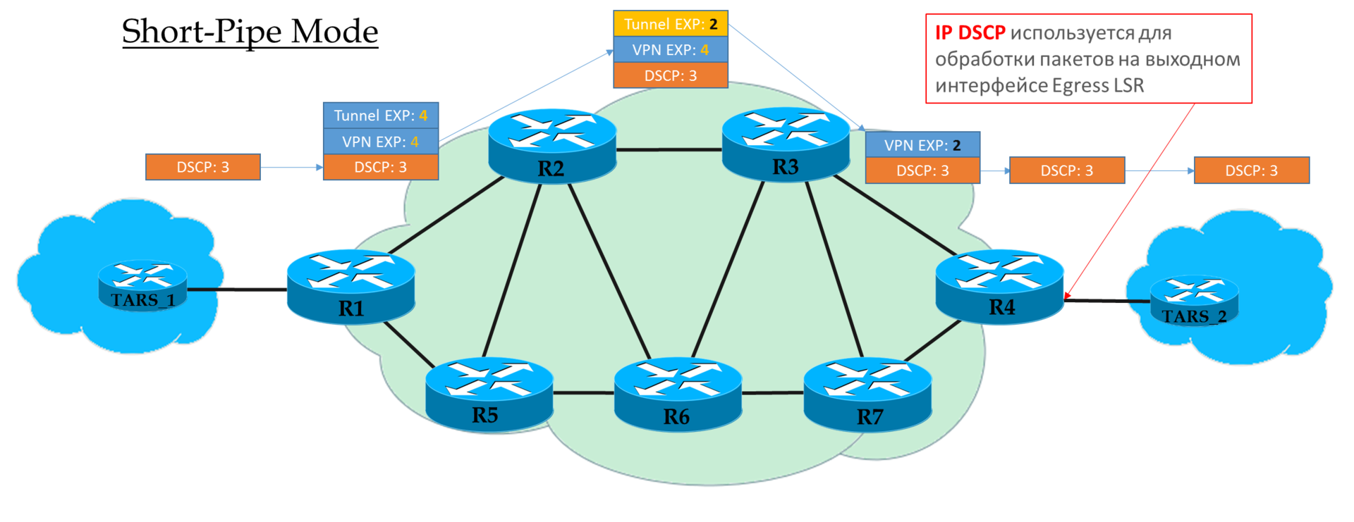
This mode can be viewed as a variation of Pipe-mode. The only difference is that at the exit from the MPLS network, the packet is processed in accordance with its IP DSCP field, and not MPLS EXP.
This means that the priority of a packet at the exit is determined by the client, and not by the operator.
Ingress PE does not trust IP DSCP incoming packets. Transit Ps look in the EXP header field. The penultimate P removes the transport label and copies the value to the VPN label.
Egress PE first removes the MPLS label, then processes the packet in queues.
Explanation from cisco .
In a typical carrier network, BGP-based L3 / L2VPN with Auto-Discovery and dedicated BGP Route Reflector are being deployed to scale and reduce load.
If LDP LSP is used as a transport, then MPLS tunnels automatically form a fully connected topology.
In such circumstances, the addition of a new PE requires only the configuration of this new PE and RR.
However, the situation is quite different if on the RSVP-TE transport. If there are a lot of PE nodes, it can be a headache to set up tunnels between all the necessary pairs of routers.
There are two approaches that allow you to avoid this conformational madness.
This approach does not require new functionality. A hierarchy is introduced - a fully meshed system of TE tunnels between P routers rises in a certain unchanging core of the network.
This is done once and never changes.
And ordinary PE routers to each other build LDP LSP.

In the stack of the MPLS packet moving in the network core, there will be three labels — VPN, LDP, RSVP-TE.
That is, LDP LSP, as if tunneled in RSVP LSP.

Illustration from the site www.nexthop.me
On, let's call it, the access segment, we have a comfortable and cozy LDP, and in the core of the network (this can be a long-distance trunk line), it is possible to control traffic.
This is a small but extremely useful improvisation that allows you to automate the tuning of tunnels.
As soon as a new PE device appears in TEDB, direct and reverse tunnels are instantly built with it.
What is the configuration? A preconfiguration pattern is created for the tunnel interface.
How do I know if a new node is PE? The template indicates the ACL, which determines with whom you can build.
For example, we take the rule that the PE nodes Loopback 127 interface will be 10.127.127.0/24, and announce it in IGP.
The simplest configuration will look like this:
I would like to summarize in one sentence: everything that was described in this article is really found in this world and not at all locks on the sand.
Therefore, briefly repeat:
MPLS TE uses RSVP-TE as a label distribution and resource reservation protocol. And he, in turn, relies on LS IGP :
We can control how RSVP LSP is built in the following ways:
IGP distributes and writes to TEDB information about:
When calculating the shortest routes, CSPF takes the requirements from the TE-Tunnel configuration, and the restrictions from the TEDB.
Tunnel Requirements:
RSVP-TE transmits in its messages:
We can send traffic to the tunnel in two main ways:
Make-Before-Break:
This is a widely used concept in MPLS TE — get it first! Before breaking something that is already working, build a new LSP.
Used when:
Shared Explicit or Fixed Filter:
Closely related to MBB concepts.
Shared Explicit (SE) - two different reservations (LSP) for one tunnel are considered related and the rinsing strip will not be reserved twice.
Fixed Filter (FF) - different LSPs from the same sender are always considered independent and the band for them is reserved separately.
The SE mode is very convenient in the MBB mechanism, and in general, the FRR and re-optimization capabilities are often disabled in the FF mode.
Tunnel Protection:
Tunnel priority:
Each tunnel has two meanings:
Usually they are equal.
0 - the highest, 7 - the lowest.
A tunnel with a higher Setup Priority value will crowd out the established tunnel with a lower Hold Priority.
Adjustment simplification mechanisms:
CoS field processing rules in MPLS DS-TE:
All abbreviations used in the article can be found in the linkmeup glossary .
Thanks
Andrei Glazkov , Alexander Klipper and Alexander Fatin for reading material and comments.
Artem Chernobay for the illustration.
My wife and children who were deprived, but allowed to close the topic MPLS.
However, the network linkmeup has grown to the size of the federal operator. The ability to manage traffic and quickly restore services has become a very important requirement in the MPLS network.
It's time to implement Traffic Engineering.
')
Issue Content:
- Prerequisites for MPLS TE
- How MPLS TE works
- Ways to route traffic to TE tunnels
- Tunnel Management Methods
- Metrics
- Bandwidth restrictions
- Tunnel Priorities
- Explicit-Path
- SRLG
- Affinity and Attribute-Flag
- Reliability and Convergence
- Path protection
- Local Protection - Fast ReRoute
- MPLS QoS
- MPLS TE IntServ
- MPLS TE DiffServ
- Modes of operation MPLS QoS
- Simplify Tunnel Tuning
- Conclusion
- useful links
Why do you need traffic engineering at all?
I will give a simple example.
Convergent network of mobile operator.
Two types of traffic:
- Mobile
- Broadband
The left shoulder is a wide 10G optical channel. Right - reserve through a leased line - 1G.
The total traffic volume is 2.5 Gb / s, mobile: 800 Mb / s.
In the event of a break of the main channel, you need to switch to the backup only mobile traffic and do it in 50ms.
Think, can we do it by standard means? Of course, we can divide traffic of different services by different VPNs, but send them by different routes - no.
Without the use of TE, all traffic will be redirected to the right shoulder, and there, who could have imagined that there is not enough bandwidth, drops will begin.
In addition, the convergence rate of OSPF or ISIS, even when using BFD, amounts to tens of ms, but after that the transport LSPs must also be reconfigured. Nowadays, it will not pass unnoticed by subscribers.
Principles of MPLS Traffic Engineering
What are the traffic management functions provided by MPLS Traffic Engineering?
- Extends the capabilities of standard IGPs, allowing you to route traffic of different classes in different ways.
- Transmits traffic through the network using MPLS switching, which means support for all VPNs.
- When constructing a route, it takes into account specified constraints, for example, what resources are necessary for this class of traffic and how many of them are available at all nodes and lines along the way, or which lines cannot be used to build tunnels.
- Fast rebuilding of tracks in accordance with the requirements in case of an accident.
- Periodic optimization of paths.
The basic mechanisms for the operation of MPLS TE were discussed in the release of SDSM 10 , where I send you for detailed consideration. And here is a brief summary.
Data plane
In terms of data transmission, TE is slightly different from LDP. Bold highlights:
- Traffic must be forcibly placed in the TE tunnel, whereas it automatically enters the LDP
Juniper is an exception.
- The first router hangs the external MPLS label (PUSH LABEL)
- Transit routers look at which interface the packet and the value of the label arrived and, changing it to a new one according to the table of labels, send it to the output interface (SWAP LABEL)
- The penultimate router removes the transport label (POP LABEL, PHP - depends on the implementation and settings)
- In case of a break in the path, traffic can be saved by forwarding packets to a pre-prepared tunnel.
Control plane
But in terms of management, the differences are much more significant. C them the rest of the way and we will understand.
So, MPLS TE wants to build an LSP taking into account the required resources and the wishes of the operator, which is why such a simple LDP with its best route is irrelevant.Terminology
LSP - Label Switched Path - generally speaking, any path through the MPLS network, but sometimes imply LDP LSP. However, we will not be so categorical - if necessary, I will indicate what I mean by LDP LSP.
RSVP LSP - LSP, respectively, built using RSVP TE, taking into account the restrictions imposed. It may also be sometimes called CR-LSP - ConstRaint-based LSP .
We will call one or more MPLS LSPs connecting two LSR routers as a tunnel . The MPLS label is essentially tunnel encapsulation.
In the case of LDP, each LSP is a separate tunnel.
In the case of RSVP, the tunnel can consist of one or more LSPs: primary, backup, best-effort, temporary.
Speaking of TE-tunnel , we will already mean specifically MPLS Traffic Engineering tunnel built by RSVP-TE.
TEDB - Traffic Engineering Data Base is the same LSDB of IS-IS / OSPF protocols, but taking into account network resources that are of interest to the TE module.
CSPF - Constrained Shortest Path First - an extension of the SPF algorithm, which looks for the shortest path, taking into account the restrictions imposed.
And his place is taken by RSVP-TE - the successor of the RSVP protocol rejected by the TCP / IP stack.
TE works in close symbiosis with IGP. Although it is more correct to call it parasitism. He forces them (OSPF or IS-IS) to serve themselves: to transfer the information he needs and thereby fill TEDB.
The process is as follows:
- IGP collects information from the entire network:
- about lines and networks,
- about metrics
- about available resources,
- about the characteristics of the lines.
And fills TEDB, where all this is reflected. - When RSVP-TE wants to build a LSP to a node, it simply calls the CSPF and says: “I want the shortest route to G with these restrictions”. Restrictions may be as follows:
- required bandwidth,
- a certain path or lines
- line characteristics. - CSPF takes restrictions from the RSVP-TE request, and real network information from TEDB. And gives the route ... or does not give, if the constraints could not be satisfied.
- When a route is received, RSVP-TE sends an RSVP PATH to this G point with a request for reservation of resources.
- Point G returns RSVP RESV — this is how resources are reserved all the way. And if the RESV is back with good news, the RSVP LSP / tunnel goes up.
All this in detail and in colors in the article 10 . And there is the simplest example in practice.
Next we will beat around the bush of this scheme:
We have a L3VPN client whose offices are connected to Linkmeup_R1 and Linkmeup_R4.
Ways to route traffic to the TE tunnel
Unlike LDP LSP, which traffic runs by default and so on, we need to send traffic to TE tunnels.
And there are for this the following ways:
- Static route
- PBR
- Igp shortcut
- Tunnel-policy *
- Or will it automatically get into the tunnel? *
Static route
The easiest to understand and the most difficult to maintain.
Linkmeup_R1(config) ip route 4.4.4.4 255.255.255.255 Tunnel 4 PBR
Essentially the same static route.
Linkmeup_R1(config) ip access-list extended lennut Linkmeup_R1(config-ext-nacl)) permit ip 172.16.0.0 0.0.0.255 172.16.1.0 0.0.0.255 Linkmeup_R1(config) route-map lennut permit 10 Linkmeup_R1(configconfig-route-map) match ip address lennut Linkmeup_R1(config-route-map) set interface Tunnel4 Linkmeup_R1(config) interface Ethernet0/3 Linkmeup_R1(config-if) ip policy route-map lennut Igp shortcut
This method is the most common and is supported by almost all manufacturers.
The router treats the tunnel as a virtual interface. And through this interface, remote routers seem to be directly connected to the local one, and not in dozens of hopes. A sort of telecommunication wormhole. It is called - shortcut - shortened path.
Flamm's Wormhole
But the default IGP protocols do not want to see this and use the physical interface to send traffic.
With the help of IGP Shortcut (in AutoRoute Announce cisarea), we force the routing protocol on the Ingress LSR to treat the tunnel as a normal line — the Egress LSR is supposedly connected directly. And accordingly, all networks located behind the Egress LSR will be accessible through the tunnel.
Thus, all whose destination point this router, or nodes behind it, will be sent to the tunnel. Including VPN packages.
Thus, the tunnel becomes a common interface, and, like any other interface, it must have a metric.
Tunnel metric
First , there are two types of metrics:
IGP metric is a well-known interface metric from the basic routing course.
TE metric is the metric that will be used when calculating the TE tunnel metric.
- By default, TE = IGP.
- By default, TE is used.
- By default, the tunnel metric is equal to the sum of the TE metrics of all the lines from Ingress to Egress by the shortest IP path (and not by the path that the tunnel goes through). That is, the metrics of the usual IP routes and routes through the tunnel will be the same, even if the tunnel is actually much longer.
Why choose the shortest path? It is logical that the tunnel metric should interrupt the metric of the best IP path. - If the metrics are equal, the router will choose the tunnel, since IGP shortcut does exactly that.
If there are IP paths that do not have common segments with a tunnel LSP, and their metrics are equal, then balancing will occur.
Secondly , we have the following methods for managing the tunnel metric:
- Change the value of the TE metric on physical interfaces.
- Tell MPLS TE to use IGP metric instead of TE.
- Accordingly, change the IGP metric of the physical interface.
- Configure the tunnel interface metrics directly:
Here a person explains in a very accessible way how metrics work.Well, in general, I recommend a resource: labminutes.com/video/sp
Forwarding adjacencies
Forwarding adjacencies is a thing of a similar nature from IGP Shortcut, with the only (significant) difference that the tunnel will now be announced to Ingress LSR IGP neighbors as a normal link. Accordingly, all surrounding routers will take it into account in their SPF calculations.
IGP Shortcut only affects the routing table on the Ingress LSR, and the surrounding neighbors do not know about this tunnel.
Tunnel-policy *
* This method depends on the manufacturer - someone has, someone does not.
Tunnel-policy is used to redirect VPN traffic exclusively to tunnels.
That is, in the VPN configuration mode (whether L2 or L3 is important), it is indicated which tunnel should be used.
There are two possibilities:
- Tunnel binding mode . Depending on the Egress PE select a specific tunnel. Applicable to RSVP LSP only.
- Select-Seq mode . The tunnel will be selected in the order specified in the configuration. This may be a TE tunnel, LDP tunnel, with or without balancing.
Juniper Features
The juna often has its own approach (see for yourself today). So it has several routing tables:
- IP routing table (inet.0)
- MPLS routing table (inet.3)
- MPLS forwarding table (mpls.0).
When placing VPN routes into an IP routing table, BGP is checked against the inet.3 MPLS table. If in it he finds the LSP before the Next Hop of the VPN route, then the traffic is automatically driven into that LSP. No additional action is required.
This is in a sense similar to the mix Tunnel-Policy and IGP Shortcut, only automatically.
Practice
All the same network, but with bandwidth limitations.
We need to provide L3VPN to the client.
The client has requirements: 8 Mb / s. Take out and put it down.
We direct traffic to the tunnel through Auto-Route.
In the laboratory, the interface limit is 10,000 Kb / s. Therefore, when specifying the requirements of the tunnel and the available lanes, we repel exclusively from this figure.Go!
So let's start with the fact that no LDP - only RSVP-TE. That is, there is no LSP until we configure the tunnel.
Although we already did all this last time, but we will start the setup from the beginning.
- Basic configuration already exists (IP + IGP)
Configuration file. - Turn on TE features
Linkmeup_R1(config) mpls traffic-eng tunnels
And at the same time on all interfaces we will immediately configure the bandwidth limitRouter(config-if) ip rsvp bandwidth _
When specifying bandwidth requirements for a tunnel, this command is mandatory — the band must be explicitly specified, otherwise IGP does not announce this information, and the CSPF will not take this line into account and will not calculate the path for the tunnel requirements.
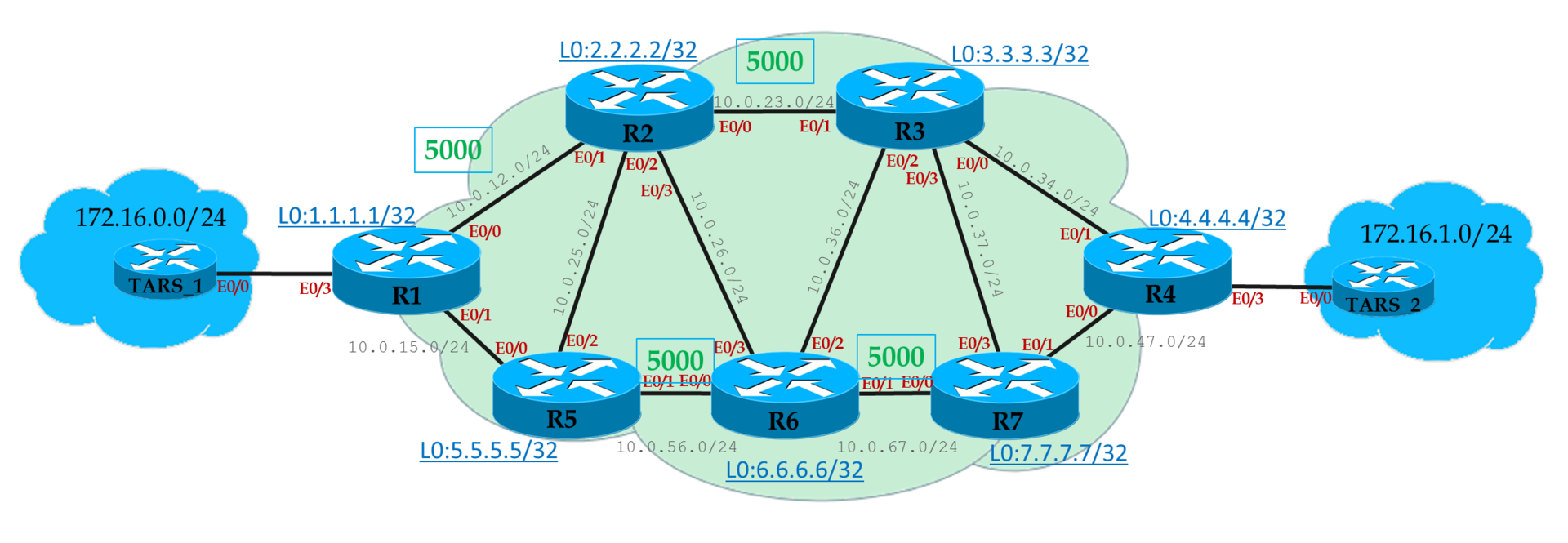
In the diagram above, I outlined which of the interfaces have a limit of 5 MB / s. If not signed, then there is no limit - set 10.It should always be remembered that this is only a reference value for calculating the TE path, and in fact the team does not limit the actual speed of TE traffic through the interface.
Linkmeup_R1(config) interface FastEthernet 0/0 Linkmeup_R1(config-if) mpls traffic-eng tunnels Linkmeup_R1(config-if) ip rsvp bandwidth 5000 Linkmeup_R1(config) interface FastEthernet 0/1 Linkmeup_R1(config-if) mpls traffic-eng tunnels Linkmeup_R1(config-if) ip rsvp bandwidth 10000Note that the ip rsvp bandwidth command points the band in one direction only. That is, if we configured it on the E0 / 0 interface in the direction of Linkmeup_R2, then this means that the bandwidth is limited to 5 MB / s for outgoing traffic only.
To restrict the other way, you need to configure the E0 / 1 interface from Linkmeup_R2.Configuration of other nodesLinkmeup_R2(config) mpls traffic-eng tunnels Linkmeup_R2(config) interface FastEthernet 0/0 Linkmeup_R2(config-if) mpls traffic-eng tunnels Linkmeup_R2(config-if) ip rsvp bandwidth 5000 Linkmeup_R2(config) interface FastEthernet 0/1 Linkmeup_R2(config-if) mpls traffic-eng tunnels Linkmeup_R2(config-if) ip rsvp bandwidth 10000 Linkmeup_R2(config) interface FastEthernet 0/2 Linkmeup_R2(config-if) mpls traffic-eng tunnels Linkmeup_R2(config-if) ip rsvp bandwidth 10000 Linkmeup_R2(config) interface FastEthernet 0/3 Linkmeup_R2(config-if) mpls traffic-eng tunnels Linkmeup_R2(config-if) ip rsvp bandwidth 10000 <hr> Linkmeup_R3(config) mpls traffic-eng tunnels Linkmeup_R3(config) interface FastEthernet 0/0 Linkmeup_R3(config-if) mpls traffic-eng tunnels Linkmeup_R3(config-if) ip rsvp bandwidth 10000 Linkmeup_R3(config) interface FastEthernet 0/1 Linkmeup_R3(config-if) mpls traffic-eng tunnels Linkmeup_R3(config-if) ip rsvp bandwidth 10000 Linkmeup_R3(config) interface FastEthernet 0/2 Linkmeup_R3(config-if) mpls traffic-eng tunnels Linkmeup_R3(config-if) ip rsvp bandwidth 10000 Linkmeup_R3(config) interface FastEthernet 0/3 Linkmeup_R3(config-if) mpls traffic-eng tunnels Linkmeup_R3(config-if) ip rsvp bandwidth 10000 <hr> Linkmeup_R4(config) mpls traffic-eng tunnels Linkmeup_R4(config) interface FastEthernet 0/0 Linkmeup_R4(config-if) mpls traffic-eng tunnels Linkmeup_R4(config-if) ip rsvp bandwidth 10000 Linkmeup_R4(config) interface FastEthernet 0/1 Linkmeup_R4(config-if) mpls traffic-eng tunnels Linkmeup_R4(config-if) ip rsvp bandwidth 10000 <hr> Linkmeup_R5(config) mpls traffic-eng tunnels Linkmeup_R5(config) interface FastEthernet 0/0 Linkmeup_R5(config-if) mpls traffic-eng tunnels Linkmeup_R5(config-if) ip rsvp bandwidth 10000 Linkmeup_R5(config) interface FastEthernet 0/1 Linkmeup_R5(config-if) mpls traffic-eng tunnels Linkmeup_R5(config-if) ip rsvp bandwidth 5000 Linkmeup_R5(config) interface FastEthernet 0/2 Linkmeup_R5(config-if) mpls traffic-eng tunnels Linkmeup_R5(config-if) ip rsvp bandwidth 10000 Linkmeup_R5(config) interface FastEthernet 0/3 Linkmeup_R5(config-if) mpls traffic-eng tunnels Linkmeup_R5(config-if) ip rsvp bandwidth 10000 <hr> Linkmeup_R6(config) mpls traffic-eng tunnels Linkmeup_R6(config) interface FastEthernet 0/0 Linkmeup_R6(config-if) mpls traffic-eng tunnels Linkmeup_R6(config-if) ip rsvp bandwidth 10000 Linkmeup_R6(config) interface FastEthernet 0/1 Linkmeup_R6(config-if) mpls traffic-eng tunnels Linkmeup_R6(config-if) ip rsvp bandwidth 10000 Linkmeup_R6(config) interface FastEthernet 0/2 Linkmeup_R6(config-if) mpls traffic-eng tunnels Linkmeup_R6(config-if) ip rsvp bandwidth 10000 Linkmeup_R6(config) interface FastEthernet 0/3 Linkmeup_R6(config-if) mpls traffic-eng tunnels Linkmeup_R6(config-if) ip rsvp bandwidth 10000 <hr> Linkmeup_R7(config) mpls traffic-eng tunnels Linkmeup_R7(config) interface FastEthernet 0/0 Linkmeup_R7(config-if) mpls traffic-eng tunnels Linkmeup_R7(config-if) ip rsvp bandwidth 10000 Linkmeup_R7(config) interface FastEthernet 0/1 Linkmeup_R7(config-if) mpls traffic-eng tunnels Linkmeup_R7(config-if) ip rsvp bandwidth 10000 Linkmeup_R7(config) interface FastEthernet 0/3 Linkmeup_R7(config-if) mpls traffic-eng tunnels Linkmeup_R7(config-if) ip rsvp bandwidth 10000 - Configure IS-IS for the ability to collect and transmit TE data
Linkmeup_R1(config) router isis Linkmeup_R1(config-router) metric-style wide Linkmeup_R1(config-router) mpls traffic-eng router-id Loopback0 Linkmeup_R1(config-router) mpls traffic-eng level-1
The metric-style wide team is obligatory, I remind you. The point is that TE uses new TLVs with extended labels, and by default ISIS only generates short ones.
Since the configuration is completely the same, for the other nodes I do not cite.
- Configure the TE tunnel.
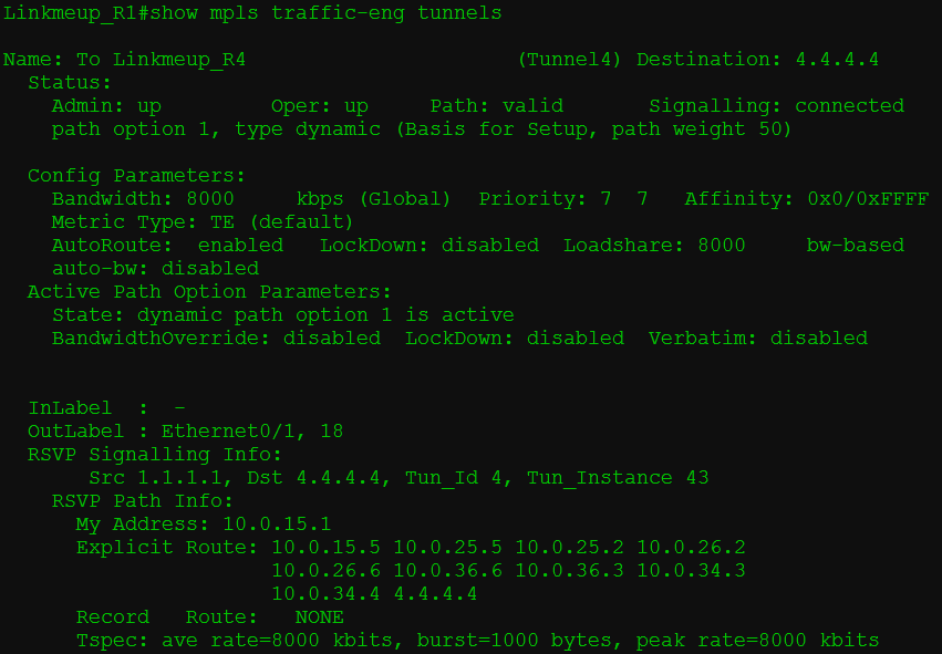
Linkmeup_R1(config) interface Tunnel4 Linkmeup_R1(config-if) description To Linkmeup_R4 Linkmeup_R1(config-if) ip unnumbered Loopback0 Linkmeup_R1(config-if) tunnel mode mpls traffic-eng Linkmeup_R1(config-if) tunnel destination 4.4.4.4 Linkmeup_R1(config-if) tunnel mpls traffic-eng bandwidth 8000 Linkmeup_R1(config-if) tunnel mpls traffic-eng path-option 1 dynamic
Here we have indicated that the tunnel is built up to node 4.4.4.4, 8 Mb / s is required, and the LSP is built dynamically (without Explicit-Path)
Immediately after this we see that the tunnel has risen.
That is, CSPF calculated the route taking into account our limitations, RSVP PATH successfully signaled the path, and RSVP RESV reserved resources all the way.Tracing shows that the path is laid exactly the way we wanted it.
The same on the back side:
And in the RSVP PATH message you can see that it carries information about the required band.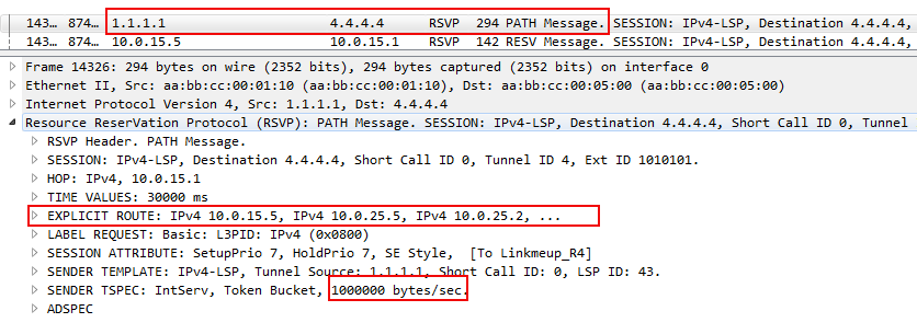
In the dump you can see the beginning of the ERO object listing all the nodes along the path of the future RSVP LSP and a request for bandwidth reservation.
It costs 1,000,000 bytes per second or exactly 8 megabits per second (unless we confuse Mega with Mobi). This value is discrete and varies with some steps. In the case of this lab - it is 250 kb / s.
You can play around with the parameters and see how the tunnel reacts to changes in the network.Linkmeup_R4(config) interface Tunnel1 Linkmeup_R4(config-if) description To Linkmeup_R1 Linkmeup_R4(config-if) ip unnumbered Loopback0 Linkmeup_R4(config-if) tunnel mode mpls traffic-eng Linkmeup_R4(config-if) tunnel destination 1.1.1.1 Linkmeup_R4(config-if) tunnel mpls traffic-eng bandwidth 8000 Linkmeup_R4(config-if) tunnel mpls traffic-eng path-option 1 dynamic - Create a VPN ( see how )
Linkmeup_R1(config) ip vrf TARS Linkmeup_R1(config-vrf) rd 64500:200 Linkmeup_R1(config-vrf) route-target export 64500:200 Linkmeup_R1(config-vrf) route-target import 64500:200 Linkmeup_R1(config-vrf) interface Ethernet0/3 Linkmeup_R1(config-if) description To TARS_1 Linkmeup_R1(config-if) ip vrf forwarding TARS Linkmeup_R1(config-if) ip address 172.16.0.1 255.255.255.0 Linkmeup_R1(config-if) router bgp 64500 Linkmeup_R1(config-router) neighbor 4.4.4.4 remote-as 64500 Linkmeup_R1(config-router) neighbor 4.4.4.4 update-source Loopback0 Linkmeup_R1(config-router) address-family vpnv4 Linkmeup_R1(config-router-af) neighbor 4.4.4.4 activate Linkmeup_R1(config-router-af) neighbor 4.4.4.4 send-community both Linkmeup_R1(config-router) address-family ipv4 vrf TARS Linkmeup_R1(config-router-af) redistribute connectedSetup on Linkmeup_R4Linkmeup_R4(config) ip vrf TARS Linkmeup_R4(config-vrf) rd 64500:200 Linkmeup_R4(config-vrf) route-target export 64500:200 Linkmeup_R4(config-vrf) route-target import 64500:200 Linkmeup_R4(config-vrf) interface Ethernet0/3 Linkmeup_R4(config-if) description To TARS_2 Linkmeup_R4(config-if) ip vrf forwarding TARS Linkmeup_R4(config-if) ip address 172.16.1.1 255.255.255.0 Linkmeup_R4(config-if) mpls traffic-eng tunnels Linkmeup_R4(config-if) router bgp 64500 Linkmeup_R4(config-router) neighbor 1.1.1.1 remote-as 64500 Linkmeup_R4(config-router) address-family vpnv4 Linkmeup_R4(config-router-af) neighbor 1.1.1.1 activate Linkmeup_R4(config-router-af) neighbor 1.1.1.1 send-community both Linkmeup_R4(config-router-af) address-family ipv4 vrf TARS
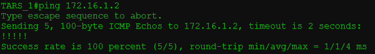
If we now try to ping, then a bummer - nothing will happen.
Note that BGP has distributed VPN routes along with their labels, but there is no data transfer.
This is because there is no link to the transport LSP, and without this, there is no point in the VPN tags. - We send traffic to it via IGP Shortcut.
One command on both PE is enough for this:Linkmeup_R1(config) interface Tunnel4 Linkmeup_R1(config-if) tunnel mpls traffic-eng autoroute announceLinkmeup_R4(config) interface Tunnel1 Linkmeup_R4(config-if) tunnel mpls traffic-eng autoroute announce
If necessary, you can also configure the metric of the tunnel interface:Linkmeup_R1(config-if) tunnel mpls traffic-eng autoroute metric relative -5Linkmeup_R4(config-if) tunnel mpls traffic-eng autoroute metric relative -5

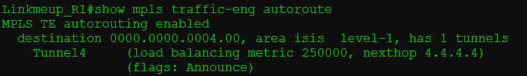
- There is a ping, there is happiness!
So what happened?
- First we set up basic TE support,
a) Enable TE support globally
b) Enable the TE function on the trunk interfaces
d) Indicate the available bandwidth of the physical interfaces
e) Forced IGP to announce TE data.
In this step, the IGP has already compiled a TEDB.- Created a tunnel (forward and reverse):
a) Indicate a destination
b) Mode of operation - TE,
c) Indicate the required band,
d) Allowed to build LSP dynamically.
In this step, the CSPF first calculates the list of nodes through which the LSP should be laid. The exhaust of this process is placed in an ERO object. then RSVP-TE uses the PATH and RESV messages to reserve resources and build the LSP.
But this is still not enough for practical use of the tunnel.- Set up L3VPN ( see how ).
When MP-BGP exchanged VRF route data, Next Hop for these routes was the Loopback address of the remote PE.
However, the routes from the BGP table are not installed in the routing table of this VRF, since we have not yet started the traffic on the LSP.- Forced IGP to consider TE-tunnel as a possible output interface.
It does not entail any changes in other parts of the network — only local action — IGP only changes the routing table of this node.
Now the LoopBack of the remote PE is available via the tunnel, and the routes are added to the VRF routing table.
That is, when an IP packet comes from a client,
a) he gets a VPN label (16).
b) from the FIB VRF TARS he knows that for this prefix the packet should be sent to the address 4.4.4.4
c) Until 4.4.4.4, there is a TE tunnel (Tunnel 4) and its output interface / tag pair is known - Ethernet0 / 1, 18 - it will be a transport one.
In this illustration, absolutely nothing to select - everything is absolutely perfect - all the information about the TE-tunnel in one team.

Now the path from R1 to R4 looks like this: R1-> R5-> R2-> R6-> R3- > R4 - all because of these damn restrictions.
Now we start messing around.
Let's try to break our working link R3-> R4, while continuous ping lasts.
LSP changed to R1-> R5-> R2-> R6-> R3-> R7-> R4 with the loss of one packet. This time can increase significantly if there is no physical line drop on the routers.
What happened?If we do not have paths that meet the specified conditions - trouble - LSP will not.
- First, R1, through the RSVP PATH ERROR message, learned that the line was broken.
- R1 sent RSVP PATH TEAR towards 4.4.4.4, and RSVP RESV TEAR going back went to remove the LSP.
- Meanwhile, on R1, CSPF has calculated a new route around the broken link.
- Then RSVP-TE signaled the new LSP R1-> R5-> R2-> R6-> R3-> R7-> R4

For example, turn off the R2-R5 line and observe the fall of the TE tunnel on R1 without further restoring it.
Re-optimizing tunnels
If the link R3-> R4 is restored, will the tunnel be rebuilt?
Yes. But not soon. Fly many packets before Ingress PE shifts its RSVP. ( Actually depends on the manufacturer )
This is called Tunnel reoptimization. At some intervals, Ingress PE causes the CSPF to check whether more optimal routes have appeared.
- CSPF finds a new path that satisfies all conditions. In our case, R1-> R5-> R2-> R6-> R3- > R4 .
- Ingress PE signals the new RSVP LSP by sending RSVP PATH.
- Having received RSVP RESV, he realizes that the new LSP is ready.
- Sends RSVP PATH TEAR to break the old LSP.
- When RSVP RESV TEAR returns, it's all over.
That is, first he builds a new RSVP LSP, lets traffic go in there and only then breaks the old one. This mechanism is called Make-Before-Break, about which at the end.
Tunnel Management Methods
So, we have enough ways to influence the traffic path with TE:
- MPLS TE path metric
- Bandwidth Limit
- Explicit-Path
- SRLG
- Administrative Groups / Affinity
MPLS TE path metric
The first most obvious method is interface metrics.
As we remember, there are IGP-metrics, and there are TE-metrics. The second ones are by default the first.
TE metrics on link interfaces not only affect the tunnel metric in terms of IGP Shortcut, but are also taken into account when building LSPs.
Why might you need to configure a TE metric other than IGP?Used for this command
For example, there is a line with a high delay value. We set the larger value of the TE-metrics to it.
Then:
When building tunnels for voice traffic, we will use the TE metric,
In tunnels for other data - IGP.
Router(config-if) mpls traffic-eng administrative-weight TE- To tell the tunnel which metric to consider:
Default value:
Router(config) mpls traffic-eng path-selection metric {igp | te} Concrete tunnel:
Router(config-if) tunnel mpls traffic-eng path-selection metric {igp | te} Cisco in detail about metrics .
Bandwidth Limit
In practice, we got acquainted with the basic function of TE - the ability to build MPLS tunnels with reservation of resources throughout the entire LSP.
But does this idea with Bandwidth bother you? Do not we return to the stone age, when there was no re-subscription. Yes, and how do you determine the magnitude of this limit? And what to do with the fact that it floats on the order of the day?
Offline Bandwidth
The method when we adjust the static value of the required band is called Offline Bandwidth.
The idea is that there is a certain program costing three in the Patriarch's Ponds, which, according to some algorithms, calculates one figure for your traffic, which you need to configure in the tunnel.
The band can be configured for the entire tunnel, as we did in practice above:
Router(config-if) tunnel mpls traffic-eng bandwidth And it is possible for a specific RSVP LSP:
Router(config-if) tunnel mpls traffic-eng path-option 1 dynamic bandwidth This value may differ from what is specified for the tunnel and has a higher priority.
At the same time, for another LSP (path-option 2, for example), the value may differ - they say, if you cannot reserve 8 Mb / s, let's try at least 5?
Offline Bandwidth has two significant drawbacks:
- Handwork, which a good engineer tries to avoid.
- Non-optimal use of resources. Well, we will assign a 300 Mb / s band to the client, reserve it on each line, but in fact it needs something from the power of 30. And only at the peak, when the database is backed up, you need 300. Inaccurately.
This option was practiced at the dawn of TE. He exists now.
However, keeping up with the times, you need to be more flexible and pliable.
Auto-Bandwidth
And Autobandwidth is great.
This mechanism tracks the loading of the tunnel for a certain period and then adapts the reservation.
Closer to the body.Terminology
Adjust Interval - the time during which the router monitors traffic and monitors peaks.
Adjust Threshold — The threshold after which RSVP re-queries the reservation.
For example, Adjust Interval we have 2 hours. The current value of the reserved bandwidth is 90 Mb / s.
Adjust Threshold - 20 Mb / s.
In the first interval, a burst of 119 Mb / s (up to 119 Mb / s) is greater than the threshold. So RSVP-TE is trying to build a new tunnel with new values for bandwidth.
In the second - 23 Mb / s (up to 142) - again more than the threshold. Update reservations whenever possible.
In the third, the maximum value drops to 137 Mb / s - the difference is only 5. Nothing happens.
In the fourth burst drops to 116 (a difference of 21) - RSVP signals the new LSP with reduced bandwidth requirements.
So, every two hours there will be a check and, possibly, a rebuilding of the tunnels.
The shorter the Adjust Interval, the more consequently the reservations will be updated and the more efficiently used available bandwidth.
Something like this at the two-hour interval will look like the 24-hour auto-bandwidth behavior.
Already noticed the problem?
Take the typical profile of morning traffic:
And such rubbish all day.
Here we measured at 8 am splash - 200 Mb / s. And for two hours this value is kept for the tunnel. And during this time, people have already come to work and launched YouTube - the average speed is already 240, and the bursts are up to 300. Until 10 am, there will be a quiet degradation. Silent, because neither the tunnel nor the Auto-Bandwidth know about it. But users know and their ITshnik also knows, believe me.
If, however, the adjustment interval is greatly reduced, then new LSPs will be constantly resigned to the network.
To solve this and other problems, there are mechanisms Overflow and Underflow . The first is for tracking the growth of traffic, the second is for the decrease.
If the difference between current redundancy and traffic surges exceeds the Overflow threshold several times in a row, RSVP TE will try to build a new LSP without waiting for the Adjust Interval to expire.
The same is true for Underflow - RSVP-TE will reregenerate LSPs with lower requirements if they notice a tendency to decrease traffic volume.
And there is only one, but a serious problem.
This is how our world works, that when traffic grows from one subscriber, it usually grows from another. And it may be that when the time comes to increase the reservation again, it will have nowhere to increase it - everything is taken. And then, if there are no other ways that meet the new conditions, the old one will be used. And no one will care that there is not enough of it, that the packages have started to get lost, that the client is looking for the director’s number in order to find an engineer who can be torn off something superfluous.
We will deal with this with the help of tunnel prioritization, which is described below.
To enable the AutoBandwidth function globally and at the same time the Adjust Interval settings:
Router(config) mpls traffic-eng auto-bw timers frequency [sec] Next, for each tunnel separately, you need to activate AutoBandwidth. You can also set a different value for the Adjust Interval, as well as set the minimum and maximum possible values for the reserved band.
Router(config) tunnel mpls traffic-eng auto-bw max-bw min-bw To configure overflow:
Router(config) tunnel mpls traffic-eng auto-bw [overflow-limit overflow-threshold ] Read more about Auto-Bandwidth in a very honest document .
Tunnel Priorities
This is the mechanism that prioritizes tunnels: which one is more important. It is applicable, as for the case of Auto-Bandwidth in particular, and for any construction of RSVP LSP in general.
Everything is very logical:
Setup Priority - the priority of installing RSVP LSP.
Hold Priority - the priority of holding RSVP LSP.
If there is not enough bandwidth on the node, and the new tunnel has a higher installation priority than the old one’s retention priority, a new one will be built - the old one is broken.
Both have 8 values: from 0 to 7. For both, 0 is the highest, 7 is the lowest.
For example, we have a LSP1 tunnel that has Hold priority 4 .
Here comes a request from RSVP-TE on LSP2 with Setup Priority 6 and Hold Priority too6 . If there is enough bandwidth, then it’s just built. If not, then the router will not allow this, because the existing tunnel is more priority than the new one (4> 6).
Suppose there are enough lanes and both tunnels went up normally.
And here comes a new request for LSP3 with Setup / Hold Priority 5 . This is higher than that of LSP2, but lower than that of LSP1. And he already lacks the band. LSP1 will definitely not be touched, because its Hold priority is still the highest. And then there are two options:
- If you break LSP2, the band is enough for LSP3. In this case, Setup LSP3 priority is higher than Hold LSP2. Ingress PE LSP2 finds out that his LSPs have broken down treacherously and will search for a new path - his luck if he finds one.
- If you break LSP2, the band is still not enough for LSP3. LSP1 router will not give up. And then LSP1 and LSP2 remain, and Ingress PE LSP3 will look for other opportunities for self-realization.
Regarding the values, they are usually chosen the same for Setup and Hold. And you should not configure Hold lower than Setup. Firstly, this is not logical. Secondly, a situation may occur when two tunnels enter a loop, when they constantly overwork each other — once one is established, the second will break it and build itself, then the first will break the second and so on.
There are two tunnel replacement modes:
Hard preemption — A higher priority LSP simply replaces a low priority LSP. Even if a low priority LSP then finds a new path, some of the traffic will be lost.
Soft preemption- The Make-Before-Break mechanism is used. A router via RSVP-TE tells the Ingress LSR of a low-priority LSP to look for a new path. A high priority LSP waits until low-priority LSP traffic switches to the new LSP.
In this case, if the path could not be found for some time, the low-priority LSP still breaks and the high-priority one is built.
Replacement priority data is transferred to the RSVP-TE PATH and is taken into account when reserving resources at intermediate nodes.
Practice
If you noticed, after configuring tunnel mpls traffic-eng badnwidth on the tunnel interface, the line tunnel mpls traffic-eng priority 7 7 automatically appears in the configuration .
The fact is that without bandwidth requirements, priorities have no meaning — you can build as many tunnels as you want through a single node - after all, the band is not reserved - and there is no command.
But, as soon as the demand appeared, along the way, priorities begin to play a role.
7 is the default value — the smallest.
Let's set up a new tunnel on Linkmeup_R1 to 4.4.4.4 with a higher priority?
Linkmeup_R1(config) interface Tunnel42 Linkmeup_R1(config-if) ip unnumbered Loopback0 Linkmeup_R1(config-if) tunnel mode mpls traffic-eng Linkmeup_R1(config-if) tunnel destination 4.4.4.4 Linkmeup_R1(config-if) tunnel mpls traffic-eng priority 4 4 Linkmeup_R1(config-if) tunnel mpls traffic-eng bandwidth 4000 Linkmeup_R1(config-if) tunnel mpls traffic-eng path-option 1 dynamic The required band is only 4 Mb / s. Therefore, the tunnel must pass along the path R1-> R2-> R3-> R4.
That's
right , here is his trace: With Tunnel4, they have only one common link R3-> R4, but its bandwidth is only 10. And two tunnels need 8 + 4 = 12.
Tunnel42 with installation priority 4 squeezes Tunnel4 with retention priority 7.
And you have to look for a new path.
And it is located:
First, the old RSVP LSP Tunnel4 is removed and a new one is signaled according to the available path.
Then RSVP-TE signals the LSP for Tunnel42.
At this point, back to Autobandwidth. A bunch of Tunnel priority + Autobandwidth gives an elegant solution.
One early morning there was little traffic, autobandwidth calculated exactly how much it was in each tunnel, and TE had enough bandwidth everywhere.
Then closer to dinner traffic grew, autobandwidth adapted, re-reserved new bands - still enough.
One evening, one by one, the tunnels begin to fly out, because TE cannot reserve a new lane.
And here it is important that the tunnels of fat clients, IP-telephony and the channel for the Ministry of Internal Affairs never fall. Then we set Hold priority for these tunnels higher than the others.
- If you try to reserve a low-priority band on the interface, where it is not enough, it will break off.
- High priority, on the contrary, will crowd out the low-priority one and occupy the vacant strip.
Turns out that
- without Autobandwidth, we either adjust the bandwidth requirements manually on the entire network, or do not do it at all by letting it go by itself,
- without Autobandwidth, we never know how much traffic is really in a tunnel,
- without Autobandwidth, we can’t limit it at all,
- without Tunnel priority, we cannot say for sure which tunnels will suffer.
Explicit-Path
The idea of Explicit-Path was more than fully disclosed in the 10th edition of the SDSM .
As you remember, CSPF calculates the shortest path based on constraints. Further, this path is transformed into an ERO object (Explicit Route Object) of the RSVP-TE PATH message, which explicitly states which path this PATH should be passed on.
So if you want some nodes to be present or vice versa absent in this path, you can explicitly specify this in the Explicit-Path, which will be one of the input constraints for the CSPF.
So, we manually specify which nodes the LSP should go through, and which ones should not.
RSVP-TE asks CSPF to calculate the route taking into account the Explicit-Path and other tunnel constraints.
If one is at odds with the other - trouble, there will be no LSP.
Explicit-Path is a strictly local restriction — only the Ingress LSR knows about it and does not transmit either in IGP announcements or in RSVP-TE messages.Setting the Explicit-path is done in two steps:
1) Creating the most explicit-path with constraints:
Router(config) ip explicit-path name Router(cfg-ip-expl-path) next-address IP- Router(cfg-ip-expl-path) exclude-address IP- ... 2) Applying it to path-option on the tunnel:
Router(config-if) tunnel mpls traffic-eng path-option 1 explicit name SRLG
SRLG - Shared Risk Link Group . Another way to influence the LSP and a great idea against flat rings .
The task of this function is to prevent the construction of the main and backup LSPs through lines that can be damaged at the same time.
For example, two fibers that physically pass in the same cable will most likely be torn by the same excavator bucket.
An SRLG group is a group of interfaces that "share the risk." ABOUT!Risk group.
Manually (of course, and how else would the router know that these are physically identical lines ) are configured interfaces that are members of one SRLG group.
Information about SRLG is distributed over the network along with IGP announcements, as is the available band or Attribute-Flag value, and is then placed in TEDB.
The CSPF should then take this information into account when calculating the shortest routes.
There are two modes:
Force Mode forces the CSPF to take into account SRLG data - if there is no other way, then the backup LSP will not be built at all.
Preffered Mode allows the construction of spare tunnels via SRLG lines, if there are no other possibilities.
The mode is set on the Ingress LSR.
To add interfaces to one risk group, the following command is entered on any nodes:
Router(config-if) mpls traffic-eng srlg And on Ingress PE enable the SRLG check:
Router(config) mpls traffic-eng auto-tunnel backup srlg exclude force/preffered What is this team, let's talk in the FRR section.
Administrative Groups or Affinity
It should be scary right now. I'm scared.
So, by this moment we learned about four traffic management tools:
- MPLS TE metric.
- Channel bandwidth requirements and substitution priority.
- Explicit-path.
- SRLG.
RFC3630 for OSPF, and for ISIS, define the TLV for the Administrative Group, which is transmitted by the IGP along with other characteristics of the lines.
, .Each time, setting up a tunnel, take into account in the Explicit Path all these details - you can go crazy.
linkmeup. , , , , . MPLS, — TE-.
, .
, 2G - — .
, 90- .
.
- .
But the new bundle is an amazing rescue that will solve all our problems, just click the “do well” button.
The idea is that we mark each interface with certain colors.
And then we say that this tunnel can go along the red and purple lines, but it cannot go along the green, yellow and brown.
Marketing Bullshit! Unclear? Me too.
So.
The Administrative Group (for Juniper: admin-group, for Cisco: Attribute-Flag) is an attribute of the physical interface that can describe its 32 discrete characteristics.
Which bit of 32 for which the operator decides is responsible.
Since we have examples in the Cisco console, then I will use the term Attribute-Flag along with the Administrative group, which is not entirely correct.
For example,
we count from the least significant bits (from the end): the
first bit in 1 means that it is optics, the
second bit in 1 means that this is a radio relay link, the
third bit in 0 means that it is a line to the access network, and 1 is a trunk interface.
the fourth bit in 1 means that the lease is the
fifth bit in 1 means that this is Balagan Telecom, the
sixth bit in 1 means that this is Filkin-Certificate of the
seventh bit in 1 means that it is a channel through the Internet without guarantees.
...
a tenth bit in 1 means that the bandwidth is less than 500 MB / s
etc. I can recycle all 32.
Affinity and mask are tunnel requirements for their path.
What kind of relationship can be formed in this triangle {Affinity, Mask, Attribute-Flag}?
(AFFINITY && MASK) == (ATTRIBUTE && MASK) If this equality holds, the tunnel can be built through this interface.
Consider an example.
We have 32 bits and a policy - for which each of them is responsible (take the example above).
In Mask, we indicate what characteristics of the channel we are interested in. For example, for a 2G tunnel it’s important
- RRL is it or not
- Trunk line or towards the access segment
- Channel via the Internet or not
Therefore, we put 1 in the mask where it’s important what it is:
Mask: 0100 0110
Took only the first 8 bits for simplicity.
Note that this is Wildcard Mask .
In Affinity, we specify what we need.
- That it was not RRL ( 0 )
- That it was the main link ( 1 )
- Channel is not via the Internet ( 0 )
Affinity: 0000 0100. Perform the
operation and we get: 0000 0100.
Now let's take three interfaces for example.
- Attribute-Flag 0000 0100 - Not RRL, trunk and not via the Internet. Attribute-Flag && Mask = 0000 0100 = Affinity && Mask - traffic can be sent here.

- Attribute-Flag 0100 0000 - Not RRL, but in the direction of the access segment, and even through the Internet. Attribute-Flag && Mask = 0100 0000 ≠ Affinity && Mask - traffic should not be allowed here.

- Attribute-Flag 0000 0101 - Optics, not RRL, trunk, and not via the Internet. Attribute-Flag && Mask = 0000 0100 = Affinity && Mask - traffic can be sent here. It does not matter whether the optics or not - the result is the same.

That is, when building the LSP, the value of Attribute-Flag will be taken into account on each link.
The default Attribute-Flag value on the interface is 0x0 . And in a sense - it is regrettable - because the result of the operation “And” with a mask will differ from the result with Affinity, which means we must configure Attribute-Flag on all interfaces.
Accordingly, within the company, policies can be developed, how to tag interfaces, and how to manage traffic. You can even assign this task to the control system so that the work of the engineer can be reduced to placing ticks in the graphical interface, and the configuration would then be applied automatically.
But in any case, this does not detract from the human factor on the one hand, and simply the incomprehensible complexity of debugging and maintenance on the other.
However, there have been cases of the integrated implementation of the Administrative Group even on the networks of Russian operators.
Other examples of use could be regional or country codes. Then it would be possible to ask through what geography to pass traffic.
In this light, 32 bits is very small, so RFC 7308 defines extended administrative groups, the number of bits in which is limited by the natural limit of LSA or MTU in general.
The guy on the fingers chews Affinity and folds it in a pile with his mouth.
Practice
Very very short. Just see what works. Short because Affinity requires Attribute-Flag configuration on all nodes and all interfaces. And this is what the last thing you want, to be honest.
We continue with the last configuration, where we have two tunnels.
Configuration file.
Tunnel42 follows the path R1-R2-R3-R4. With him and play.
The default Attribute-Flag is 0x0. Therefore, we take it as Affinity - that is, all the interfaces we have under the condition. In addition to R3-R4, on which we configure Attribute-Flag 0x1. Since the equality will not be fulfilled - the CSPF will not be able to build the shortest path through this link.
Linkmeup_R1(config) interface Tunnel4 Linkmeup_R1(config-if) tunnel mpls trafic-eng affinity 0x0 mask 0x1 Linkmeup_R3(config) interface e0/0 Linkmeup_R3(config-if) mpls trafic-eng attribute-flags 0x1 And we observe how the tunnel went around this link.
However, Tunnel4 fell apart safely. The default Affinity value is also 0x0, but the mask is 0xFFFF. Therefore, he also did not fit into the reconfigured link R3-R4.
But, we could adjust the mask 0x0 on it - ignore any Affinity and Attribute-Flag bits:
Linkmeup_R1(config) interface Tunnel4 Linkmeup_R1(config-if) tunnel mpls trafic-eng affinity 0x0 mask 0x0 And then the tunnel will rise, not taking into account these restrictions.
Reliability and convergence
In practice, we have already seen that rebuilding a tunnel in the event of a breakdown takes several seconds. Well, it was not so bad at the time of my grandfather.
The whole history of the development of computer networks is the story of the fight against accidents, the struggle for the speed of convergence, for the reduction of the break time.
What do we have in service?
- Physical protection. For example, APS to SONET or LAG to Ethernet.
- IP - the solution to all problems. IGP, BGP, VRRP and so on.
- A set of technologies in MPLS.
If evolution built people according to this principle, we would die predominantly from old age (the second reason for the number of deaths would be “perish under its own weight”).Physical protection typically provides a convergence time of ± 50 ms.
IP is good, but converges in seconds, or even minutes.
MPLS TE offers two options to increase stability and reduce service interruption time.
- Path protection
- Local protection
The first implements protection at the level of the entire LSP, the second at the level of a link or node - and it is called FRR - Fast ReRoute.
Path protection
When setting up a tunnel, we can specify how many and which LSPs we want to build.
- Primary - this is the main LSP , which will be used to transmit traffic.
- Secondary — LSP . Ingress PE — .
:- Standby — : LSP . . Hot-standby.
- Non-standby — , LSP . LSP Ingress LSP RSVP-TE , . . Ordinary.
- Standby — : LSP . . Hot-standby.
- Best Effort — , RSVP-TE - .
Protection is not only and not so much about the restoration of the service, as about the speed of this recovery.
In this vein, it is clear that non-standby is not the case. Based on IGP, RSVP-TE first waits for updating the routing information, then it has to work out itself - the count for seconds. The signal is a notification from RSVP-TE or BFD that the LSP is no longer live, or the information from the IGP about the topology change.
For the Standby case, the primary RSVP LSP and the standby are built simultaneously. Accordingly, as soon as the Ingress LSR fixes the gap of
Local Protection (FRR)
But the FRR - Fast Reroute - allows you to save even those cars that are already now striving for the purpose, not even knowing that the bridge has collapsed there. That is, FRR is like a detour on the section of the road where repairs are underway, and Backup LSP is another route.
FRR uses workarounds and is described in RFC4090. The average switching time after detection of an accident is 50ms.
This is a thing that just turns on, and then it works automatically. That is, from the point of view of configuration, it looks elementary.
As is usually the case, things that are simply customized, hide something interesting under a coat.
So, FRR has two functions:
- Protect the line - Link Protection.
- Protect one node - Node Protection.
Therefore, it is called Local Protection - it does not monitor the entire LSP, but only checks the availability of the nearest link or node.
When terrible happens, it simply takes the packets to the bypass tunnel.
Figure a) shows line protection. On b) - protection of nodes.
Take LSP from R1 to R4. Each node along the path, except R4, will try to build its own workarounds.
So R1 to protect the line R1-R2 will choose the path R1-> R5-> R2. And to protect against the fall of the node R2: R1-> R5-> R6-> R3.
R2 must protect line R2-R3 and node R3.
ETC.
Let's first deal with Link Protection?Terminology
PLR - Point of Local Repair - point of consumption. This is the node that initiates line or node protection. It can be Ingress PE or any transit P, but not Egress PE
MP - Merge Point - the vanishing point where the protective tunnel lands. Any transit P or Egress PE, but not Ingress PE.
Primary LSP or Protected LSP - the original LSP that requires protection.
Bypass LSP - Protective LSP .
NHOP - Next Hop - the next node after the PLR in the Primary LSP.
NNHOP - Next Next Hop - respectively the next node after Next Hop.
FRR Link Protection
The task of FRR is to save those bags that fly directly into the abyss of the collapsed link, leading them to this very Bypass LSP.
When the PLR notices that the line through which the transit LSP lies has fallen, it instantly redirects traffic. Note that it is not Ingress PE that does this, but the node where the break occurred. A link drop is fixed by a drop in an interface or a BFD session.
You can compare the FRR with the arrow on the track.
To redirect packets so quickly, the Bypass LSP must be built in advance. This is what happens.
Each node in the course of Primary LSP is looking for how to get around the fall of the next link and the fall of the next hop.
That is, it launches the full LSP engine:
- CSPF to MP (NHOP for link drops and NNHOP for node drops)
- Sends an RSVP PATH computed path with a reservation request.
- RSVP RESV if the reservation succeeds.
Tunnels are built automatically and are not displayed in the configuration. But otherwise, these are ordinary tunnels, through which you can view information or trace them.
Technically, bare FRR requires manual tuning of all Bypass tunnels. That is, the operator himself must provide all the places where something can break down and set up a reservation.Now we need to solve two problems -
Yeah. , .
, .
AutoTunnel, Primary LSP Bypass-.
Ingress LSR :Router(config) mpls traffic-eng auto-tunnel backup
auto-tunnel , FRR-. .
- how to put packets from Primary LSP into this Bypass LSP.
- How on MP to understand what to do with the received happiness.
Everything is very simple - FRR LSP is a regular tunnel. That is, it is enough for us to tunnel our previous tunnel in the section from PLR to MP, which means add one more MPLS tag to each packet. There will be 3 of them: VPN, Tunnel, FRR.
So, when a packet arrives at the PLR at the time of the crash, it first does the usual external label SWAP, as if it should go through the old (currently broken interface) and he also knows that you need to transfer it to the FRR tunnel - adds another tag
Next, the packet is switched by Bypass LSP according to standard rules - the external (FRR) label changes, and the two internal ones remain unchanged.
On the last but one node, the external label is removed - PHP and before the MP the package comes with the original two.
MP receives the packet, looks at the transport label and then commutes the packet, as if nothing happened.
It is important that all this works only if the global tag pool is used, and not interface-specific. So MP does not take into account which interface the packet came from with this label.
FRR Node Protection
Everything is absolutely the same except for the transport tag - PLR should know what label the NNHOP is waiting for.
The tunnel is now not built to the next node, but through one - NNHOP. This is assisted by the attribute of the RSVP message - LRO (Label Request Object). Being in the RSVP PATH, he asks the nodes to highlight tags along the way.
And in the RSVP RESV Label Object contains these same highlighted tags.
Bandwidth Protection
When signaling Bypass LSP, the question arises: whether to reserve resources.
If yes, then it is already called Bandwidth Protection.
In this case, it usually does not make sense to reserve resources twice for the same tunnel. Well, really - from the fact that we have taken the traffic from Primary to Bypass, it does not follow that the resources will be used twice on PLR and MP? Moreover, the free line may not be enough. Therefore, the concept of SE (Shared Explicit) is introduced. If this attribute is set in the original RSVP PATH, resources will not be backed up twice - intermediate nodes will know that this is not a completely independent LSP - this is the old idea of something.
So, the procedure is as follows:
- When setting up a tunnel, we indicate that we want a FRR and a set of attributes of this tunnel:
- — RSVP TE LSP — , NNHOP.
- ( ).
- SE — / .
- Ingress LSR Primary LSP.
- PLR Bypass LSP NHOP. :
- LSR ID MP (NHOP NNHOP NHOP).
- , MP FEC.
- .
- «», : SE .
- Bypass LSP.
- .
- PLR
- , BFD .
- , , BFD RSVP RSVP Hello.
- PLR . Ingress LSR :
- , MP.
- Bypass .
- Bypass LSP.
- Ingress PE RSVP — , LSP.
- Bypass LSP, Bypass LSP, Bypass ( PHP ).
- MP MPLS , , , , .
- , FRR .
- After switching, Ingres LSR will constantly try to restore Primary LSP using the Make-Before-Break mechanism.
When he succeeds, the new LSP will be called the Modified LSP .
Notice that MP did nothing at all - only at first it took part in building the LSP - he didn’t even know that this was some kind of Bypass LSP - for him it was a normal request from RSVP TE.
FRR Modes.
The only question that still needs to be discussed about FRR is which LSPs should be redirected? He is not the only one who probably goes through this PLR?
There are two options:
- Many-to-One (or Facility mode ). Respectively - all will fly through one tunnel.
- One-to-One . LSP .
The first option is preferred because it uses resources more efficiently. All that was above about the Facility mode .
One-to-One introduces a couple of new terms:
Detour LSP - spare tunnel . Same Backup LSP, but Detour protects only one Primary LSP,
DMP - Detour Merge Point - Same MP.
This method is very similar to Facility, but there is one significant difference. In Facility mode, the existing LSPs were tunneled into the Bypass LSP, getting the third label on the stack. In the One-to-One mode, when you go around an obstacle, two labels will remain in the stack, that is, it will look and work like the most common LSP.
PLR when a crash is detected, the received packets of the old LSPs will be sent in a new way, simply by performing the usual Swap transport tag. But the label and output interface will be new - from the Detour LSP.
DMP also performs a normal swap transport label. Instead of the Detour LSP tag, it substitutes the old one from the Primary LSP and sends it further.
I disassembled the Facility mode in detail, because it is the most commonly used.
, FRR, .That's all you need to know about FRR.
, , , .
, Juniper, One-to-One Fast Reroute — . - FRR . link link-node protection Facility mode.
, Cisco One-to-One, FRR , MPLS- , . — - .
Cisco , LSP . More details .
If we talk about Huawei, then by default the Facility mode assumes manual tuning of the tunnels to the PLR. But there is an Auto-FRR mode - then everything will work automatically.
As they say, the farther into the selva, the angrier the gaucho.
Cisco.
Juniper.
Practice
We continue with the same network from the point at which we stopped (except for affinity).
Configuration file.
Path-Protection
Add Standby LSP with lower bandwidth requirements: 3 Mb / s.
Linkmeup_R1(config) interface tunnel4 Linkmeup_R1(config-if) tunnel mpls traf path-option protect 1 dynamic bandwidth 3000 Note that Preference (1) must be the same as Primary LSP.
The path of the protective tunnel was laid down as follows:
First, on the R1-R2 line, 4 Mb / s out of 5 already occupied Tunnel42. Therefore, there is no band left for the spare LSP Tunnel4.
Secondly, the primary and backup LSPs usually use the Shared Explicit (SE) bandwidth reservation method, which means that there will not be a bandwidth reserved for the same tunnel twice. Therefore, through 10 Mb / s, the link R1-R5 managed to lay both the main LSP (8 Mb / s) and the backup (3 Mb / s).
Thirdly, you can see that the backup LSP on the R6-R4 segment has chosen the same path as the main one. Therefore, the use of Explicit-path can sometimes be quite justified.
For pleasure and satisfaction, you can pull the link R2-R5 and make sure that the traffic of subscribers is almost not interrupted.
If in your current configuration your ping has stopped and is not restored, try to understand why.
Local-Protection (FRR)
If you are still pulling link R2-R5, please stop and return it to the Up state.So we want to configure FRR for this Tunnel4.
In addition, for clarity of the FRR, you will have to remove Path-Protection.
configuration file
1) Turn on FRR on the tunnel
Linkmeup_R1(config) interface tunnel4 Linkmeup_R1(config-if) tunnel mpls traffic-eng fast-reroute It is logical to do this at the other end
Linkmeup_R4(config) interface tunnel1 Linkmeup_R4(config-if) tunnel mpls traffic-eng fast-reroute Right after that, RSVP signaled a new attribute along the LSP.
He said that link protection was needed for this LSP.
But the tunnels do not appear yet.
2) Now you need to enable the ability to build tunnels automatically:
Linkmeup_R1(config) mpls traffic-eng auto-tunnel backup What does this team do? Checks which interfaces are used for tunnels that require Local-protection, and tries to protect the link and the next node, so on each node (where it can) it builds the necessary tunnels.
For example, on Linkmeup_R2 would be 4:
- to protect the link R2-> R6 (R2-> R5-> R6).

- for protection against the fall of the node R6: R2-> R6-> R3 (R2-> R3).

- to protect the link R2-> R5 (R2-> R6-> R5)

- to protect against the fall of the node R5: R2-> R5-> R1 (R2-> R1).

Please note that protection tunnels are built without any bandwidth accounting, until this is discussed separately.
So, now I want to break the line R2-> R6.
In theory, to protect this line, we have Tunnel65436 (R2-> R5-> R6). But then the full path will look a little strange: R1-> R5-> R2-> R5 -> R6-R3-> R4 - that is, along the R5-R2 line, the traffic will pass twice - back and forth. Therefore, R2 briefly turns on the intellect and selects Tunnel65437, which directly leads to R3.
Then on section R2-R3 we should see two labels in the stack - VPN and tunnel. The bypass tag will not be inserted because PHP.
If you want to see all three tags, to make sure that the FRR is working, enter the command to R2
Linkmeup_R2(config) mpls traffic-eng auto-tunnel backup nhop-only R2 .
. .
, , Bypass- FRR Primary.
, Primary LSP ICMP-. Bypass LSP, Primary LSP, , , .
— Primary LSP R2->R3 - , Bypass LSP, , .
Bypass Primary , Bypass.
We look at the VPN and transport labels R1:
PUSH VPN - 16
PUSH Tunnel - 26
We look at the table of labels on R5:
SWAP Tunnel 26-> 16
We look FRR on R2:
SWAP Tunnel 16-> 27 (label that is waiting for NHOP)
PUSH Bypass Implicit Null - that is, the label is not really inserted.
Tags on R3:
PHP: POP Tunnel 27 (wait).
We look at the dump on the site - 2 tags (implicit null was not really added):
Perfectly!
And finally, a couple of light topics without practice.
MPLS QoS
A separate issue will be dedicated to QoS. Get ready. But not to talk a little about it now would be unforgivable.
MPLS TE IntServ
So MPLS TE uses the IntServ QoS paradigm - pre-reservation of resources all the way.
That is, we are initially confident that the necessary band (and other requirements) will be provided to the service. In this case, the packets inside the tunnel (LSP) are all equivalent.
However, it happens that the client traffic grows. Maybe at some point its volume exceeds the static threshold, and there is no longer a free band, or Autobandwidth has not yet managed to work out the speed increase.
One way or another, packets are beginning to be discarded, and without any parsing whether they are important or not.
That is, the idea of IntServ in the MPLS TE implementation by itself does not guarantee that there will be no problems on every single node.
MPLS TE DiffServ
And who is responsible for Per-Hop Behavior? Remind me? DiffServ? And if we do not combine these two beautiful paradigms?
Indeed, in the MPLS header there is an EXP field, which was planned to be an Expeditional, but it has long been officially used to set the priority of packets and is called the Traffic class. That's just the old habit of it and now continue to call EXP,
This is called MPLS DiffServ-aware Traffic Engineering - MPLS DS-TE.
The idea, generally speaking, is to provide MPLS-packages with the quality of service expected by the original packages. That is, ideally, it is necessary to make a 1 to 1 correspondence. But EXP is only 3 bits, that is, 8 priority values, while DSCP is 6 bits (64 values), whatever one may say, but the details with such archiving are lost.
Thus, there are two approaches:
E-LSP - EXP-Inferred LSP . To score and rejoice at what we have.
L-LSP - Label-Inferred LSP . Encode priority with EXP + tag.
E-lsp
For the case when we initially deal with the DSCP field, we transfer only the three most significant (left) bits of the DSCP to MPLS EXP.
And yes, we accept the loss of detail.
When the PDU arrives at the Ingress LSR, we place it in the tunnel and set the priority in the EXP field.
Well, for example, in one tunnel we will have the data of broadband access and fixed telephony. Naturally, we will give priority to telephony 5, and everything else to 0.
Then even if a traffic jam occurs within one tunnel, the weak will die first.
L-lsp
In this case, the QoS data is encoded into a bunch of Tag + EXP. It is assumed that the label specifies the processing mechanism in the queues, and the label - the priority of packet drop.
PHB information must be signaled during the installation of the LSP.
Each L-LSP carries only one type of service.
Today, operators for the most part define four traffic classes: BE, AF, EF and CS. E-LSP is more than enough for this, so L-LSP is not only practically not used, but moreover, not all vendors have it. Therefore, I will not dwell further on the comparison of methods.
QoS Modes
But what is interesting is what CoS field to trust on each node: IP DSCP, Tunnel EXP or VPN EXP?
There are three modes:
- Uniform mode
- Pipe mode
- Short-Pipe Mode
Remember, already faced with such concepts when parsing TTL in MPLS L3VPN ? Something similar here.
Uniform mode
End-to-End.
Ingress PE IP DSCP ( , , «» ) MPLS EXP ( , VPN ). Ingress PE EXP MPLS.
P EXP. , .
(PHP) EXP VPN-. , — Uniform, .
Egress PE VPN, EXP IP DSCP, .
That is, if somewhere in the middle the value of the EXP tag in the tunnel header has changed, then this change will be inherited by the IP packet.
Pipe mode
If, on Ingress PE, we decided not to trust the DSCP value, then the EXP value that the operator wishes is inserted into the MPLS headers.
But it is permissible to copy those that were in the DSCP. For example, you can override the values — copy everything up to EF, and CS6 and CS7 map to EF.
Each transit P looks only at the EXP of the upper MPLS header.
The last but one node removes the transport label (PHP) and copies the EXP value to the VPN header.
Egress PE first processes the packet, based on the EXP field in the MPLS header, and only then removes it, while not copying the value in the DSCP.
That is, regardless of what happened to the EXP field in the MPLS headers, IP DSCP remains unchanged.
Such a scenario can be used when the operator has his own domain Diff-Serv, and he does not want client traffic to somehow influence him.
Short-Pipe Mode
This mode can be viewed as a variation of Pipe-mode. The only difference is that at the exit from the MPLS network, the packet is processed in accordance with its IP DSCP field, and not MPLS EXP.
This means that the priority of a packet at the exit is determined by the client, and not by the operator.
Ingress PE does not trust IP DSCP incoming packets. Transit Ps look in the EXP header field. The penultimate P removes the transport label and copies the value to the VPN label.
Egress PE first removes the MPLS label, then processes the packet in queues.
Explanation from cisco .
Simplify Tunnel Tuning
In a typical carrier network, BGP-based L3 / L2VPN with Auto-Discovery and dedicated BGP Route Reflector are being deployed to scale and reduce load.
If LDP LSP is used as a transport, then MPLS tunnels automatically form a fully connected topology.
In such circumstances, the addition of a new PE requires only the configuration of this new PE and RR.
However, the situation is quite different if on the RSVP-TE transport. If there are a lot of PE nodes, it can be a headache to set up tunnels between all the necessary pairs of routers.
There are two approaches that allow you to avoid this conformational madness.
- LDP over TE
- RSVP Auto-Mesh
LDP over TE
This approach does not require new functionality. A hierarchy is introduced - a fully meshed system of TE tunnels between P routers rises in a certain unchanging core of the network.
This is done once and never changes.
And ordinary PE routers to each other build LDP LSP.
In the stack of the MPLS packet moving in the network core, there will be three labels — VPN, LDP, RSVP-TE.
That is, LDP LSP, as if tunneled in RSVP LSP.
Illustration from the site www.nexthop.me
On, let's call it, the access segment, we have a comfortable and cozy LDP, and in the core of the network (this can be a long-distance trunk line), it is possible to control traffic.
RSVP Auto-Mesh / Auto-Tunnel
This is a small but extremely useful improvisation that allows you to automate the tuning of tunnels.
As soon as a new PE device appears in TEDB, direct and reverse tunnels are instantly built with it.
What is the configuration? A preconfiguration pattern is created for the tunnel interface.
How do I know if a new node is PE? The template indicates the ACL, which determines with whom you can build.
For example, we take the rule that the PE nodes Loopback 127 interface will be 10.127.127.0/24, and announce it in IGP.
The simplest configuration will look like this:
- With a familiar command, we enable the Auto-tunnel feature in Mesh mode:
Router(config) mpls traffic-eng auto-tunnel mesh - Identify potential PEs in an ACL:
Router(config) ip access-list standard 1 Router(config-std-nacl) permit source 10.127.127.0 0.0.0.255 - We get a configuration template:
Router(config) interface auto-template 1 Router(config-if) ip unnumbered Loopback127 Router(config-if) tunnel mode mpls Router(config-if) tunnel mpls traffic-eng autoroute announce Router(config-if) tunnel mpls traffic-eng priority 4 4 Router(config-if) tunnel mpls traffic-eng auto-bw Router(config-if) tunnel mpls traffic-eng path-option 4 dynamic Router(config-if) tunnel destination access-list 1
Conclusion
I would like to summarize in one sentence: everything that was described in this article is really found in this world and not at all locks on the sand.
Therefore, briefly repeat:
MPLS TE uses RSVP-TE as a label distribution and resource reservation protocol. And he, in turn, relies on LS IGP :
- OSPF with its Opaque LSA
- IS-IS with TLV
We can control how RSVP LSP is built in the following ways:
- Metric (IGP or TE)
- Resource requirements
- Explicit-path
- SRLG
- Administrative Groups / Affinity
IGP distributes and writes to TEDB information about:
- Line condition
- Metrics
- Free Resources with Hold Priority
- SRLG
- Attribute-Flag / Administrative Group
When calculating the shortest routes, CSPF takes the requirements from the TE-Tunnel configuration, and the restrictions from the TEDB.
Tunnel Requirements:
- Required lane and installation priority
- Affinity / Administrative Group
- Explicit-Path
RSVP-TE transmits in its messages:
- Required band for reservation with priority of setting and holding
- Backup Mode - SE or FF
- ERO - LSP node list
- RRO - a real list of nodes and tags on each site
- FRR Needs Information
We can send traffic to the tunnel in two main ways:
- Static route or PBR
- IGP Shortcut (or Forwarding Adjacencies)
- Vendor-dependent mechanisms: automatically on Juniper or Tunnel-policy on Huawei / HP
Make-Before-Break:
This is a widely used concept in MPLS TE — get it first! Before breaking something that is already working, build a new LSP.
Used when:
- Re-optimizing tunnels
- FRR
- An important tunnel is trying to oust the less important.
Shared Explicit or Fixed Filter:
Closely related to MBB concepts.
Shared Explicit (SE) - two different reservations (LSP) for one tunnel are considered related and the rinsing strip will not be reserved twice.
Fixed Filter (FF) - different LSPs from the same sender are always considered independent and the band for them is reserved separately.
The SE mode is very convenient in the MBB mechanism, and in general, the FRR and re-optimization capabilities are often disabled in the FF mode.
Tunnel Protection:
- When the line / node breaks, FastReRoute fulfills the first 50 ms, saving those packets that already go to the LSP.
- Then the Ingress LSR finds out about the problems with the main LSP and redirects traffic to the backup LSP — all subsequent packets are already saved.
- Next, Ingress LSR attempts to restore the primary LSP to bypass the problem area, if possible.
Tunnel priority:
Each tunnel has two meanings:
- Setup Priority
- Hold Priority.
Usually they are equal.
0 - the highest, 7 - the lowest.
A tunnel with a higher Setup Priority value will crowd out the established tunnel with a lower Hold Priority.
Adjustment simplification mechanisms:
- LDP over TE
- RSVP Auto-Mesh / Auto-tunnel
CoS field processing rules in MPLS DS-TE:
- Uniform. CoS PDU .
- Pipe. CoS PDU . Egress PE MPLS.
- Short-pipe. CoS PDU . Egress PE CoS PDU.
useful links
- cisco MPLS TE. :
- Cisco FRR: MPLS Traffic Engineering. Traffic Protection using Fast Re-route (FRR)
- Autobandwidth: Deploying MPLS Traffic Engineering
- MPLS TE Affinity
- DiffServ Tunneling Modes for MPLS Networks
- MPLS: labminutes.com
I also remind you that the list of the best books on networks is here .Someone will say: SDTSM is becoming more and more strange. You break away from reality.
And it will be wrong: next time, let us return to the burning topics - QoS. The long-awaited, promising, and how difficult, as much and useless.
It will be the same trash and waste for 140k characters, but about what you work with every day.
All abbreviations used in the article can be found in the linkmeup glossary .
Thanks
Andrei Glazkov , Alexander Klipper and Alexander Fatin for reading material and comments.
Artem Chernobay for the illustration.
My wife and children who were deprived, but allowed to close the topic MPLS.
Source: https://habr.com/ru/post/338578/
All Articles