learnopengl. Lessons 3.1 (Assimp) + 3.2 (Mesh class)

Assimp
In all the lessons, we mostly used our little friend - the container, but after a while, even our best friends become a bit boring. In a large graphic application, there are usually many models that are much more pleasant to look at than our static container. Although, unlike the container, it will be very difficult for us, manually, to determine all the vertices, normals and textural coordinates of such complex models as, for example, a house or human-like characters. Instead, we will import the models into our application; models that have been carefully drawn in 3D editors such as Blender, 3DS MAX or Maya.
Menu
These so-called 3D modeling tools allow artists to create complex models and apply textures to them using a process called texture mapping (uv-mapping). The tools automatically generate all vertex coordinates, normal vertices and texture coordinates, exporting them to a model file. Thus, artists have an extensive set of tools for creating high-quality models without worrying about technical details. All technical aspects are hidden in the exported file. We, as graphics programmers, need to take care of these technical details.
So our job is to analyze these exported model files and extract all the relevant information so that we can store them in a format that OpenGL understands. However, a common problem is that there are dozens of different file formats, each of which exports these models in its own unique way. Wavefront model formats like .obj contain only model data with little material information, such as color models or diffuse / specular maps, while model files based on XML are extremely extensive and contain models, lighting, a lot of material information , animation and more. The obj format is considered to be easily analyzed. It is recommended to get acquainted with the structure of the file, for example, on a page on Wikipedia. This should give you basic information about how to store the model in an obj format file.
')
In general, there are many different formats where the stored data structure is different. Therefore, if we want to import a model from these files, we need to write the importer ourselves, for each format we want to import. Fortunately for us, for this there is a library.
Library for loading models
Assimp is a very popular library for importing models, which stands for Open Asset Import Library. This library can import many different formats that contain models, saving the data that is imported in a simple hierarchical data structure. As soon as Assimp finishes loading the models, we will be able to get all the data we need from this structure. No matter what file format we import, the data access in the structures does not change, the structure remains the same for all the different file formats.
When importing a model using Assimp, the library loads the entire model into a scene object (Scene) containing all the data of the imported model. Assimp then creates a collection of nodes, where each node contains indexes to the data stored in the scene object, each node can have a descendant. A simple model of the structure of Assimp is presented below:
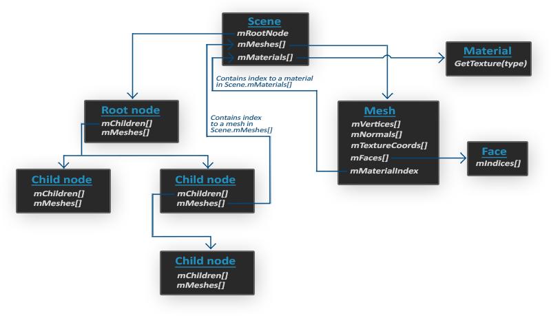
- All model data is contained in the Scene object, as well as data on materials and polygonal mesh. The scene also contains a link to the root node of the scene.
- The Root node can have children (Child nodes) (as well as other nodes) and can have indices that indicate polygon mesh data stored in an array of the mMeshes scene object. The mMeshes array of the root node contains specific polygon mesh objects, and the values in the mMeshes array for any descendant are only indices for sampling the array of the root node grids.
- The polygon mesh object contains all the relevant data needed for drawing: vertex coordinates, normal vectors, texture coordinates, faces, and material information for the object.
- A polygonal mesh (mesh) contains several faces. Faces are the primitives of an object (triangles, squares, points). They contain vertex indices that make up the primitives. Since we have vertices and their indices, drawing is much easier thanks to element buffer objects ( Hello Triangle )
- Also, a polygonal mesh contains an index on a material object (Material), which has several functions for obtaining material properties.
And so, we first need to load our object into the scene object, recursively retrieve the corresponding polygon mesh objects from each of the nodes (recursively traversing the descendants of each node) and process each element of the polygonal mesh to extract vertices, indices and material properties. The result is a collection of polygonal meshes that we will contain in the Model object.
Mesh - a set of vertices and triangles
A single mesh (Mesh) is the minimum data set required for output by means of OpenGL (vertex, index, material) data. The model, however, usually consists of several grids. When modeling objects in special programs (Blender, 3D max), artists do not create a whole model from a single form. Usually, each model has several sub-models / forms of which it consists. Think of a person as a model: the artist usually models the head, limbs, clothing, weapons, all as separate components, then combining all the sub-models, gets the original.
In the following lessons, we will create our own Model and Mesh classes that load and store imported models using the structure we just described. If we want to draw a model, then we do not derive it entirely, but carry out the derivation of each of the grids making up the model separately. Before we can import the models, we need to first include Assimp in our project.
Build assimp
You can download Assimp from this page by selecting the appropriate version. At the time of writing, the latest version of Assimp was 3.1.1. It is recommended to compile the libraries yourself, as their precompiled libraries do not work on most systems. Review the Create Window lesson if you forgot how to compile the library yourself using CMake.
Several problems appeared during the build of Assimp, so I’ll mark them here, with their solutions in case any of you get the same errors:
- CMake gives errors about missing DiretX libraries, such as:
Could not locate DirectX
CMake Error at cmake-modules / FindPkgMacros.cmake: 110 (message):
Required library DirectX not found! Install the library (including dev packages)
and try again. If the library is already installed
manually in cmake.
You need to install DirectX SDK, in case it has not been installed. You can download the SDK here . - During installation, the DirectX SDK pops up error code s1023.
In this case, you first need to install the C ++ package, before installing the SDK,
as described here .
- After setup is complete, you can create a project file, open it, and compile libraries.
- By default, Assimp is provided as a dynamic library, so we need to include in the project a corresponding dll named assimp.DLL. You can simply file the DLL in the same folder as the executable file of the application.
- After compilation, the library and its dll file will be located in the code / Debug or code / Release folders.
- Then simply link the library file and the dll file with your project, and make sure that you also remember to include the Assimp header files.
If you want to use multithreading to increase performance, you can build Assimp with Boost. Full instructions are here .
At this point, you had to compile Assimp and inject it into your application.
Mesh class
Using Assimp, we can load many different models into our application, but after downloading, the data is still stored in the Assimp structure. We need to convert this data to a format that OpenGL understands, so that we can draw the model. In the previous lesson, we learned that a polygonal mesh is a single drawable entity, so let's start by defining our own Mesh class.
Let's think about what data set we need for our class. A polygonal mesh needs a set of vertices, where each vertex contains a position vector, a normal vector and a vector of texture coordinates. Polygonal mesh should also contain indexes
for indexed rendering, and data for materials.
Now, we can define the structure of the vertex:
struct Vertex { glm::vec3 Position; glm::vec3 Normal; glm::vec2 TexCoords; }; Each vertex is stored in a Vertex structure, which can be used to index each vertex. In addition to the Vertex structure, we also need to create a structure that stores texture data.
struct Texture { unsigned int id; string type; }; It stores id and texture type (diffuse or specular).
Having written the structures, you can start writing our class:
class Mesh { public: /* Mesh Data */ vector<Vertex> vertices; vector<unsigned int> indices; vector<Texture> textures; /* Functions */ Mesh(vector<Vertex> vertices, vector<unsigned int> indices, vector<Texture> textures); void Draw(Shader shader); private: /* Render data */ unsigned int VAO, VBO, EBO; /* Functions */ void setupMesh(); }; As you can see, the class is not very complicated. The constructor takes all the data we need, in the setupMesh method we initialize the buffers, in the Draw method we will draw our polygonal mesh. Notice that the draw function takes a shader object so that we can set the corresponding uniform variables to draw.
The constructor code is quite simple, we simply assign the class arguments, the corresponding arguments. We also call the setupMesh function:
Mesh(vector<Vertex> vertices, vector<unsigned int> indices, vector<Texture> textures) { this->vertices = vertices; this->indices = indices; this->textures = textures; setupMesh(); } As you can see, nothing unusual happens here. Next, go to the setupMesh function.
Initialization
Thanks to the constructor, we have all the data we need that we can use to draw. However, we first need to configure the appropriate buffers. At this point you should have no problems with these concepts, but perhaps we will surprise you a little how to transfer data to the buffer that is in the structure:
void setupMesh() { glGenVertexArrays(1, &VAO); glGenBuffers(1, &VBO); glGenBuffers(1, &EBO); glBindVertexArray(VAO); glBindBuffer(GL_ARRAY_BUFFER, VBO); glBufferData(GL_ARRAY_BUFFER, vertices.size() * sizeof(Vertex), &vertices[0], GL_STATIC_DRAW); glBindBuffer(GL_ELEMENT_ARRAY_BUFFER, EBO); glBufferData(GL_ELEMENT_ARRAY_BUFFER, indices.size() * sizeof(unsigned int), &indices[0], GL_STATIC_DRAW); // vertex positions glEnableVertexAttribArray(0); glVertexAttribPointer(0, 3, GL_FLOAT, GL_FALSE, sizeof(Vertex), (void*)0); // vertex normals glEnableVertexAttribArray(1); glVertexAttribPointer(1, 3, GL_FLOAT, GL_FALSE, sizeof(Vertex), (void*)offsetof(Vertex, Normal)); // vertex texture coords glEnableVertexAttribArray(2); glVertexAttribPointer(2, 2, GL_FLOAT, GL_FALSE, sizeof(Vertex), (void*)offsetof(Vertex, TexCoords)); glBindVertexArray(0); } The code is not much different than what you expected, but a few small tricks were used using the Vertex structure.
In C ++, structures have an excellent property — their memory is consistent. That is, if we presented a structure as an array of data, then it would contain variables in the order in which they are defined in the structure itself. For example, if we fill the Vertex structure with some values, then their placement in memory will be:
Vertex vertex; vertex.Position = glm::vec3(0.2f, 0.4f, 0.6f); vertex.Normal = glm::vec3(0.0f, 1.0f, 0.0f); vertex.TexCoords = glm::vec2(1.0f, 0.0f); // = [0.2f, 0.4f, 0.6f, 0.0f, 1.0f, 0.0f, 1.0f, 0.0f]; Thanks to this property, for example, if we apply the sizeof function to our structure, it will return the size of all the arguments that are defined in it. It should weigh 32 bytes.
(8 * 4 - size 1 float). We can use this for the glBufferData function:
glBufferData(GL_ARRAY_BUFFER, vertices.size() * sizeof(Vertex), vertices[0], GL_STATIC_DRAW); We also use the offsetof macro, which takes the structure as the first argument, and the name of the structure variable as the second. And it returns the offset in bytes of the specified structure, to the variable passed in the second argument. This is ideal for determining the last parameter of the glVertexAttribPointer function:
glVertexAttribPointer(1, 3, GL_FLOAT, GL_FALSE, sizeof(Vertex), (void*)offsetof(Vertex, Normal)); The offset is now determined using the macro offsetof, which, in this case, sets the byte offset for the normal vector. Please also note that we specify a step size equal to the size of the structure.
Using this structure not only provides more readable code, but also allows us to expand it in the future. If we want to use some other vertex art attribute, we can easily add it to our structure, and because of its flexibility, the code will not break.
Drawing
The last function we need to write is Draw. But before drawing our polygons, we first need to bind our textures before calling the glDrawElements function. However, it is a bit hard, because we don’t know how much texture (if any) we have and what type they are. And also, how to set texture units and texture objects in a shader?
To solve this problem, we will adopt some naming conventions: each diffuse texture is called texture_diffuseN, and each highlight texture map must be called texture_specularN, where N is any number starting from 1 to the maximum number of allowed textures. Suppose we have 3 diffuse textures and 2 specular textures for a particular polygonal mesh, we must define them like this:
uniform sampler2D texture_diffuse1; uniform sampler2D texture_diffuse2; uniform sampler2D texture_diffuse3; uniform sampler2D texture_specular1; uniform sampler2D texture_specular2; Thanks to this agreement, we can define as many texture objects as we want, and if the polygonal mesh does contain a lot of textures, we know what their names will be. We can process any number of textures on a single polygonal mesh and the developer can freely use as many textures as he wants, simply by defining additional texture objects in the shader.
Besides this solution, there are also many others, and if you don’t like it, you can show your creative ability and come up with your own solution.
Draw method code:
void Draw(Shader shader) { unsigned int diffuseNr = 1; unsigned int specularNr = 1; for(unsigned int i = 0; i < textures.size(); i++) { glActiveTexture(GL_TEXTURE0 + i); // , // stringstream ss; string number; string name = textures[i].type; if(name == "texture_diffuse") ss << diffuseNr++; // unsigned int stream else if(name == "texture_specular") ss << specularNr++; // unsigned int stream number = ss.str(); shader.setFloat(("material." + name + number).c_str(), i); glBindTexture(GL_TEXTURE_2D, textures[i].id); } glActiveTexture(GL_TEXTURE0); // glBindVertexArray(VAO); glDrawElements(GL_TRIANGLES, indices.size(), GL_UNSIGNED_INT, 0); glBindVertexArray(0); } This is not the most beautiful code, but C ++ is partly to blame for this, since, for example, there is no such type conversion as int into string. We go over the N-textures and define the assignment of their types to a string variable, so that we would then have an idea what the number of the specific texture type is. Next, we find out the number of our texture object, and finally, we set to this texture object the number corresponding to the active texture unit and bind the texture. Notice that we are going to store textural objects in the Material structure, as we usually did.
Please note that by increasing the diffuse and specular counters, we immediately transfer them to stringstream. The right increment in C ++ increases the value by 1, but returns the old value.
You can find the full code for the Mesh class here .
In the next lesson, we will create a Model class that works as a container for objects of the Mesh class and actually implements the Assimp boot interface.
Source: https://habr.com/ru/post/338436/
All Articles