Autopilot with your hands. We add electronic control steer-by-wire to a regular car
Hello. Any autopilot obviously needs to not only make management decisions, but also make the car obey these decisions. Today we will see how to modify the usual car with a fully electronic steering system (steer-by-wire) using very affordable means. It turns out that the car itself is not very necessary for development, and most of the functionality can be easily debugged at home or in the office. Starring the well-known components from hobby electronics stores.
Think for a second, what is needed for an electronic control system? A servo that can turn the wheels and a controller to control the servo. Suddenly, all this is already in most modern cars, and is called "power steering". Traditional purely mechanical (usually hydraulic) amplifiers are rapidly disappearing from the market, giving way to nodes with an electronic control unit (ECU). So, the task is immediately simplified: we can only “persuade” the existing amplifier ECU to issue the necessary commands to the servo.
KIA Cee'd from the 2015 model year turned out to be very convenient for refinement (most likely, its co-platform from KIA / Hyundai is most likely the same). Several factors agreed at the same time:
- The power steering is fully electric, there is no fuss with hydraulics, it costs a penny (relatively) on disassembly. All necessary wiring is brought out and easily accessible.
- The amplifier is integrated with the steering column, so there is easy access to it by car and any additional electronics will remain in the cabin in greenhouse conditions (as opposed to amplifiers integrated into the steering rack).
- It is very important - there is an example of successful completion of a similar KIA Soul. American PolySync is developing an upgrade from Soul to a fully drive-by-wire platform for UAVs , and you can see a lot of useful things on their githaba .
So, obtained at the disposal of the steering column assembly:

We will make it spin. To do this, create an impression on the control unit that
- He is in a car with a running engine.
- The driver applies the rotational force to the steering wheel.
Let's go in order.
Car simulation
It is necessary to understand the interface between the electronic control unit (ECU) of the amplifier and the rest of the car. Googling electrical circuit see the picture:

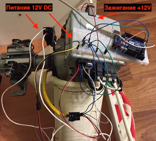
From the diagram it is clear that the physical interface is very simple:
- Power supply (12V constant) via E29 connector.
- Ignition on signal (12V) via connector M46.
- CAN data bus also via connector M46.
Appearance and pinout connectors find on the same site.
With power and ignition, everything is simple, we take 12V from a conventional computer power supply. But if you simply apply power and ignition, the amplifier will not fully turn on and will not be amplified. Additionally, information is needed from other car units: whether the engine is working (so as not to waste battery energy when it is turned off), the current speed (to make the steering wheel "harder" at speed), surely something else.
Data exchange between electronic units in modern cars is organized on CAN buses (Controller Area Network) . This is a broadcast (packets have no destination addresses) local network on a twisted pair, where each unit can publish its data. Each data type has its own identifier. For example, in our case, the power steering sends the values of the steering angle with ID 0x2B0. Often there are several physically separated tires so that minor blocks such as window regulators do not interfere with the exchange between critical components. Cee'd uses two buses: C-CAN and B-CAN (the diagram is here , in the section "Information about the data transmission channel"). Almost all the blocks with it hang on the C-CAN and we will work.
CAN bus adapter selection
First of all, you need a CAN interface for a computer. There is a detailed overview of possible solutions here , for example , prices range from tens to hundreds of dollars. On devices we have relatively available:
- Adapters assembled with aliexpress . They did not try, according to rumors quite a lot of marriage and software apparently only under Windows.
- Arduino shields on the MCP2515 / MCP2551, mostly design clones from seeed in any shop on the subject. But it is necessary to combine such a shield not with the Arduino (I could not get the bundle to work at playback at the desired speed), but with the Raspberry Pi. See the appendix below for detailed instructions .
- USB adapter CANHacker Baby , development Artemka86 . Favorably differs from the options with aliexpress with excellent support "first-hand" from the developer (tested personally, Artem approaches the matter with the soul). Also a plus is the support of the standard LAWICEL protocol compatible with a wide range of software.
There is also a lot of software ( for review here again ). The easiest option is Linux c can-utils from SocketCAN , for which thanks to the Volkswagen engineers. SocketCAN is a big plus in standardization - any USB device with support for the LAWICEL protocol (pdf) is seen by the system as a normal network interface. Thus, we avoid binding to the vendor-specific software of a specific device. The current version of CANHacker has a slight incompatibility with the can-utils runtime for working with USB, so we take the patched version from here . Raspberry Pi with CAN Shield works with the can-utils stock package from Raspbian OS without problems.
Bus connection, packet writing
With the connection to the individual node on the stand, everything is simple: we connect the CAN-High contact of the adapter with the CAN-High of the vehicle node, CAN-Low - with CAN-Low. According to the standard, between CAN-High and CAN-Low there should be 2 closing resistors of 120 Ohm each, in practice everything usually works on a rather wide resistance range, for example, I have one 110 Ohm.
On the car, the closing resistor is not needed (they are already there, so that the bus itself works). Depending on the model of car, you may have to tinker with the physical access to the bus wiring. The most convenient option is the OBD-II connector (on-board diagnostic) , it is mandatory on all cars produced in Europe from 2001-2004 and located no more than 60 cm from the steering wheel. On the Cee'd connector to the left under the steering wheel, behind the plastic cover of the fuse box.
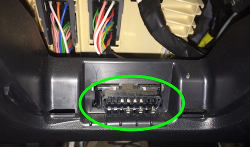
The OBD-II pinout is standardized and includes a CAN bus (CANH on pin 6, CANL on 14). We were lucky, the Koreans took the path of least resistance and brought out the C-CAN, on which all the important nodes hang, directly to the diagnostic connector:

As a result, you can listen to all the internal traffic on Cee'd, without disassembling anything in the car. When the car is not yours, and friends let you tinker - a big plus. But such a freebie is not everywhere. In Volkswagen, for example, the service CAN is isolated from the OBD by the gateway, so you would have to connect like this:

Having connected all the contacts, we raise the network interface:
$ sudo slcand -o -c -s6 -S 115200 ttyACM0 slcan0 && sleep 1 && sudo ifconfig slcan0 up Check that the network is working and data is being received (by turning on the ignition):
$ cansniffer slcan0 And finally, if everything is fine, you can write a log:
$ candump -L slcan0 > real-car-can-log.txt Here you need to start the engine, because the power steering is turned on for the actual gain only when the engine is running, and we need to stand on the stand to increase it.
Playback tire recording on stand
With the recorded log from the car, you can go back to the stand and start the deception of our lonely amplifier. First of all, let us remember that the car has its own amplifier, it also sends data to the CAN bus, and these packets are also in our log. We filter them to avoid conflicts. Connect to the amplifier on the stand, see what it gives out:
$ $ candump slcan0 slcan0 2B0 [5] 00 00 00 00 00 slcan0 2B0 [5] FF 7F FF 06 F1 slcan0 2B0 [5] FF 7F FF 06 C2 slcan0 2B0 [5] FF 7F FF 06 D3 slcan0 2B0 [5] FF 7F FF 06 A4 slcan0 2B0 [5] FF 7F FF 06 B5 slcan0 2B0 [5] FF 7F FF 06 86 slcan0 2B0 [5] FF 7F FF 06 97 slcan0 2B0 [5] FF 7F FF 06 68 slcan0 5E4 [3] 00 00 00 slcan0 2B0 [5] FF 7F FF 06 79 slcan0 2B0 [5] FF 7F FF 06 4A .... We see that 2B0 packets (the current steering angle) and, less commonly, 5E4 (some kind of general amplifier status) are sent. Filter them from the common log:
$ cat real-car-can-log.txt | grep -v ' 2B0' | grep -v ' 5E4 ' > can-log-no-steering.txt Filtered log can be submitted for playback:
% sudo ifconfig slcan0 txqueuelen 1000 $ canplayer -I can-log-no-steering.txt If everything worked out successfully, the amplifier will work, turning the steering shaft with your hand will become much easier. So, we made the knot work in normal mode, we can proceed to the simulation of efforts on the steering wheel.
Emulation effort on the steering wheel
Torque on the steering shaft and the angle of rotation is measured by the built-in sensor unit, from which the wiring harness goes to the amplifier control unit:

The control unit processes the sensor signals and commands the servo to create additional effort to turn the steering shaft.
Check sensor signal format
According to PolySync , the Soul, which has a common platform with Cee'd, has two analog torque sensors. The signal of each is the deviation of the DC voltage level from the base 2.5V, the wires in the harness are green and blue. Check that we have the same thing:
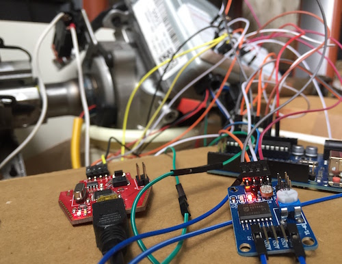
- We disconnect the connector on the computer, we forward the necessary contacts through the layout and we get to the analog inputs of the arduino.
- We load the sketch , in a cycle measuring tension and printing them in the terminal.
- We start Serial Plotter in Arduino IDE, we turn a steering shaft. We see the result on the graph, the scheme coincides with Soul:
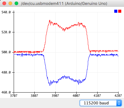
- We rejoice at the time saved.
Sensor signal emulation
Go to the emulation of the sensor signal. To do this, we put our module in the open circuit between the sensor and the computer, we will transmit the real signal from the sensor and, on command, shift it to a fixed level (depicting the force applied to the steering column). With the help of one arduino, this will not work: there is no full-fledged digital-to-analog converter, which could produce a constant voltage. The analog inputs of the arduino are not very suitable for us either - although there are only 6 pins for them, the ADC channel in the controller is only one, and switching between pins takes considerable time.
It is necessary to add an external DAC / ADC to the arduino. I came across the YL-40 modules ( described in pdf ) based on the PCF8591 chip - each with 4 channels of 8-bit ADC and 1 8-bit DAC. The module can communicate with arduino via I2C protocol . It will take a little dopilivanie (literally): the Chinese comrades put on the board the LED indicating the voltage at the DAC output - it must be disconnected. Otherwise, the current flowing through the diode will not allow the DAC to raise the voltage at the output to more than 4.2V (instead of the standard 5V). Diode disconnect, otkovyrivaya resistor R4 on the back of the board.

Also, the inputs are soldered toy loads (thermistor, photoresistor, something else), disconnect them, removing the jumpers, so as not to interfere.

With the interface to the arduino there is a nuance - we need 2 DAC channels, respectively 2 modules, but they have the same I2C addresses (they are embedded in the chip). Although the chip allows you to change your I2C address, closing certain legs to + 5V instead of ground, these jumpers on the board are not divorced. Instead of soldering, take a crutch - two different I2C libraries on arduino (standard Wire and SoftI2CMaster ), each for its own pair of pins. We get modules on different tires, the conflict disappears.
The rest is straightforward - we put the modules in the open circuit from the sensors, connect them to the arduino, load the sketch . Details on the pinout of the connection are in the comments in the sketch. It remains to include everything in the collection, the sequence is important here:
- Turn on arduino, open Serial Monitor. It is important to start arduino first, do not stop or interrupt. Otherwise, the voltage at the outputs of the DACs will reset, the amplifier's ECU will detect the signal error from the sensors, go to a safe environment and have to restart all over again.
- We power the amplifier, we connect the ignition.
- We start playback of the CAN-bus log.
- Now, at the
landrcommands, the amplifier will turn the steering shaft through the Serial Monitor. Victory is declared.
Today, everything is in line with software development (integration with the CAN bus, reading the current angle of rotation and dynamic torque control from there, so that the external controller can set a fixed angle of rotation of the steering wheel and the system can withstand it), testing the vehicle (you cannot simulate resistance from wheels). It is possible to replace 8-bit DAC / ADC with 10 or 12 bits (I took the first one that came to hand). The steering network is also in the process, I hope to make a post soon.
Thanks Artemka86 for valuable advice on working with CAN and help with the equipment.
Resources for further immersion
- Car Hacking: The definitive source . You can start with Car Hacking for Poories , there are well covered bases. The rest is also interesting, but with an emphasis on unauthorized access.
- The Car Hacker's Handbook: A Guide for the Penetration Tester . More details than in Car Hacking: The definitive source, also an emphasis on unauthorized access. If you read as the first introduction to the topic, you need to adapt to skip large chunks.
- Car Hacking 101: Tools of the Trade , MCD Software - Tool Reviews. Mostly uninteresting exotic in my opinion.
- Open Source Car Control is an open source platform for KIA Soul, under development. They make a complete solution (steering wheel, accelerator, brakes), turning on the hardware on the car (mainly for brakes - additional brake drives are put, something changes in brake hydraulics, etc.). There was no release yet, but many things are already visible.
Bonus Combine Raspberry Pi and Arduino CAN shield
First of all, attention, CAN Shield and raspberry pi cannot be connected directly , they are not voltage compatible. On Arduino UNO-compatible boards, the logic voltage is 5V, and on a raspberry pi only 3.3V, so a direct connection will only burn the pins involved.
We will need:
- Raspberry Pi (tested on version 3B).
- Arduino CAN Shield on MCP2515 / MCP2551.
- A logic level converter for 5 channels or more (2 to 4 channels are possible, but more connections will be needed). I got this
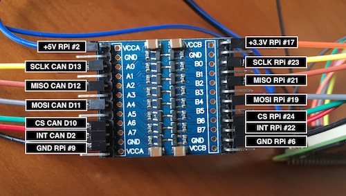
It is necessary to power the CAN shield (5V), SPI data interface connections (4 pins: MOSI, MISO, SCLK, CS) and 1 pin of the interrupt signal. Everything, except power supply, goes through a level converter, which in turn also needs to be powered.
On the schemes we are looking for the necessary pins.
Raspberry Pi:

CAN Shield:
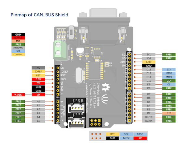
We get the result:
- SPI on raspberry pi 19, 21, 23, 24 (MOSI, MISO, SCLK, CS) correspond to D11, D12, D13, D9 (or on some versions of D10) on the CAN label.
- Interruption from D2 on the shield can be made on any GPIO pin raspberry, I have it pin 22 (GPIO 25). Pin number will indicate in the software when setting up.
We connect through the converter, we get the necessary supply voltage on each side of the converter, it turns out such noodles:
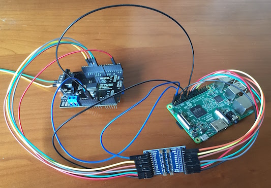
Everything except 5V power and ground to the shield goes through the converter:
Go to setting up the software (standard Raspbian).
We include support for SPI and CAN module. Add to
/boot/config.txtdtparam=spi=on dtoverlay=mcp2515-can0,oscillator=16000000,interrupt=25,spimaxfrequency=1000000 dtoverlay=spi0-hw-csHere
interrupt=25indicates the pin, which interrupted with Shield. Indexing goes on GPIO pins, sointerrupt=25is GPIO 25, it’s also pin 22 for end-to-end indexing of all pins. It is also important to indicate the frequency of the SPI interfacespimaxfrequency, since the default is 10 MHz - too high for the shield, it just won't connect.Reboot the raspberry pi, check the connection with the shield:
$ dmesg ... [ 12.985754] CAN device driver interface [ 13.014774] mcp251x spi0.0 can0: MCP2515 successfully initialized. ...Install
can-utils:$ sudo apt install can-utilsWe start the virtual network interface:
$ sudo /sbin/ip link set can0 up type can bitrate 500000 $ sudo ifconfig can0 txqueuelen 1000The second command is important when playing a large amount of data from a raspberry pi, that is, when a full CAN bus log is recorded on the car, it is reproduced for an isolated node on the stand. Without an increase in the buffer, it is likely to overflow when there are several CAN packets in the log at small intervals, and then the connection hangs.
- Done, you can use
candump,cansnifferand everything else fromcan-utils.
')
Source: https://habr.com/ru/post/338322/
All Articles