Methods for developing motion software flow sensors that work with Arduino
Hi, Habr! I want to propose the implementation of two approaches to the development of motion sensor software that works in conjunction with the Arduino board. Neither motion sensor [1], nor Arduino [2]. additional advertising is not needed.
Let's compare existing programming methods in terms of simplicity and ease of use. We suggest starting the article with an introduction to the characteristics of the selected motion sensor.
The main sensor that will be used is the PIR motion sensor [3] .
')
PIR sensors are small, inexpensive, consume less power and are compatible with hardware platforms such as the Arduino.
It uses a pair of pyroelectric sensors that detect infrared radiation. It has a range of up to 6 meters, which is enough for the project.

In addition, you will need LEDs: green and red. Cords, resistors and layout: you need a bundle of wires and a layout to complete the connections. You will also need two resistors for 220 ohms and one 10 kΩ.
The next components will be the Arduino board: the Arduino Uno board. To connect the Arduino board with a computer, use a USB cable.
Before you start working with the hardware system, you need to sketch a project in the form of a block diagram. We use the project with the cycle shown in the figure.
The project is executed in a cycle as soon as movement is detected, and the corresponding LED actions are performed:

With a single Arduino instruction, you can turn the LED on or off.
To perform a blink operation, it will be necessary to perform the on and off actions again with a time delay between actions so that the output of the PIR sensor can calm down.
We will use the same thread when writing code for both programming methods.
The simplest way to design hardware for such projects is prototyping. The tool used for this purpose is called fritzing.
Fritzing actively supports Arduino and other popular open source hardware platforms. The following figure shows the layout for a project developed using Fritzing. We connect the components as shown in the picture:

To complete the circuit assembly, perform the following steps:
Below is a schematic diagram of the electronics circuit that we developed earlier. The diagram is also obtained using Fritzing:
Now the system is ready to launch the Arduino program.
After completing the connection of the circuit go directly to the programming sections. It is recommended to use to check the connection circuit and check the status of the sensor.
We assume that the Arduino board is already equipped with a StandardFirmata sketch. Otherwise, you need to upload a StandardFirmata sketch to the Arduino board.
The best way to verify the implementation of the scheme is to use the Firmata testing program, which was described in a previous article. According to the project settings, the PIR sensor issues events to the Arduino pin 7.
In the test program, change the output type 7 to Input and wave your hand over the sensor, and you can see the status of the pin as shown in the following screenshot:

Check the LED connections by setting pins 12 and 13 as output contacts and switching buttons to set the status of the contacts. If the LEDs blink when the button is switched, the connections work flawlessly.
To launch the project we perform:
Like any other Arduino program, the code has two mandatory functions: setup () and loop (). It also has a custom function blinkLED () for a specific action, which will be explained later.
In the previous code snippet, variables were assigned for output by the Arduino at the beginning of the program. In the setup () function, we configured these variables to define as input or output pins:
Here, pirPin, redLedPin, and greenLedPin are digital pins 7, 12, and 13, respectively. In the same function, we also configured the Arduino board for a serial connection at a speed of 9600 bps:
In the loop () function, we repeatedly control the input signal from the pirPin digital contact for motion detection. The output of this contact is HIGH when movement is detected, and LOW otherwise.
This logic is implemented using a simple if-else statement. When this condition is met, the function calls the user-defined function blinkLED () to perform the corresponding action on the LEDs. User functions are a very important aspect of any programming language.
Functions are used when a code segment is re-executed to perform the same action. The user can create a custom function to organize code or perform repetitive actions. To successfully use a custom function, the user must call them from the required Arduino functions, such as loop (), setup (), or any other function that leads to these mandatory functions:
The following is a custom function that was used in the project code:
In the project, the blinkLED () function does not reconfigure any value when it is called from the loop () function. Therefore, the return type is void. When calling a function, we pass the pin number and the message as parameters:
These parameters are then used in the action taken (writing a message to the serial port and setting the status of the LED) using the blinkLED () function. This function also introduces a delay for flashing using the delay () function.
The designed system was tested in the “Hardware Testing” section using manual inputs through the Firmata testing program. It is necessary to make sure that the project performs objective tasks autonomously and repeatedly.
With the USB port connected to the computer, you need to open the sequential monitoring tool from the IDEArduino environment by going to the “Tools” menu | SerialMonitor or by pressing Ctrl + Shift + M. A message similar to the one shown should appear on the serial monitor:

When writing the function blinkLED () to perform actions, we included an action for writing a string through the serial port. Move your hand over the PIR sensor so that the PIR sensor can detect movement.
This event should cause the system to flash with a red LED and display the line detected by the movement on the serial monitor. If there is no movement for a while, you can see the green LED blinking until the next movement through the PIR sensor is detected.
You can use the editor of your choice, but make sure that files with the .py extension are saved. Copy the following lines of code into a new file and save it as test.py:
To run this file, run the following command on the terminal where the test.py file is saved:
You should be able to see the PythonProgramming text printed on the terminal. As you can see, the file starts with #! / Usr / bin / python, which is the default installation location for Python. By adding this line to your Python code, you can directly execute the Python file from the terminal. On Unix-based operating systems, you need to make the test.py executable file using the following command:
Now, since your file is executable, you can directly run the file using the following command:
Now create a new Python file with the following code snippet and run it. It is necessary to change the value of the port variable in accordance with your operating system:
There are two main programming components in this code: the pyFirmata methods and the Python function to perform the flashing action. The program repeatedly detects motion events and performs a blinking action.
In this method, we implemented a while statement to keep the program in a loop until the user completes the work manually. You can complete the code using the key combination Ctrl + C.
Work with the Arduino board and the Firmata protocol needs to be started by initializing the Arduino board as a variable. The pyFirmata method, which allows the user to assign the board to a Python variable, looks like this:
Once the value of the variable is assigned, you can perform various actions, such as reading a pin or sending a signal for output using this variable. To assign a role to a contact, use the get_pin () method. In the next line of the code, d represents the digital output, 7 is the output number, and i means that the output type is the input output:
Once pin and its role are assigned to a variable, this variable can be used to read or write values on the output:
You can directly write data to a specific output, as described in the following code:
Here, the write (1) method sends a HIGH signal to the output.
The Python function begins with the def keyword, followed by the function name and input parameters or arguments. The function definition ends with a colon (:) and then indents. The return statement completes the function. It also passes this expression to the place where the function is called.
If the return statement is saved without an expression, it is considered that it passed the return value to None:
The previous structure can be used to create custom functions for performing repetitive tasks. In our project, we have the function blinkLED (pin, message) to execute the flashing LED. This function sends a 1 (HIGH) and 0 (LOW) value to the specified digital contact, and also prints a message on the terminal. It also introduces a delay to simulate a blinking action:
After running the Python code on the terminal, you can begin testing. If everything goes according to the project, you should be able to see the following output in the terminal:
You should be able to see the motion detection line on the terminal when any movement is detected by the PIR sensor. The advantage of using Python is that minor changes, such as changing the blinking speed or replacing LED roles, can be accomplished by simply changing the Python code without using an Arduino or an electrical circuit.
A comparative analysis of the results of the practical implementation of the project by the two programming methods that we used in this work shows that the method that uses only the Arduino sketch represents the traditional programming paradigm of the microcontroller. Although this method is simpler to implement, it lacks the extensiveness achieved by the Python-Arduino interface. Thus, for practical use, we make a choice in favor of the Python-Arduino method.
Let's compare existing programming methods in terms of simplicity and ease of use. We suggest starting the article with an introduction to the characteristics of the selected motion sensor.
The main sensor that will be used is the PIR motion sensor [3] .
')
PIR sensors are small, inexpensive, consume less power and are compatible with hardware platforms such as the Arduino.
It uses a pair of pyroelectric sensors that detect infrared radiation. It has a range of up to 6 meters, which is enough for the project.
In addition, you will need LEDs: green and red. Cords, resistors and layout: you need a bundle of wires and a layout to complete the connections. You will also need two resistors for 220 ohms and one 10 kΩ.
The next components will be the Arduino board: the Arduino Uno board. To connect the Arduino board with a computer, use a USB cable.
Software flow development
Before you start working with the hardware system, you need to sketch a project in the form of a block diagram. We use the project with the cycle shown in the figure.
The project is executed in a cycle as soon as movement is detected, and the corresponding LED actions are performed:
With a single Arduino instruction, you can turn the LED on or off.
To perform a blink operation, it will be necessary to perform the on and off actions again with a time delay between actions so that the output of the PIR sensor can calm down.
We will use the same thread when writing code for both programming methods.
Hardware design
The simplest way to design hardware for such projects is prototyping. The tool used for this purpose is called fritzing.
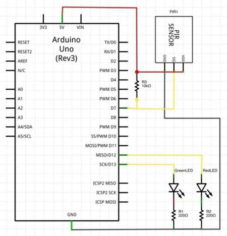
Fritzing actively supports Arduino and other popular open source hardware platforms. The following figure shows the layout for a project developed using Fritzing. We connect the components as shown in the picture:
To complete the circuit assembly, perform the following steps:
- Connect VCC (+ 5V) and ground from the Arduino to the layout.
- Connect the anode (long wire) of the red LED to the digital output 12 of the Arduino board. Connect the cathode (short wire) of the red LED to ground with the help of 220 Ohm resistors.
- Connect the anode (long wire) of the green LED to the digital output 13 of the Arduino board. Connect the cathode (short wire) of the green LED to the ground using 220 ohm resistors.
- Connect the VDD of the PIR sensor to the VCC on the layout. Use the same posting color to represent the same category of connections. This will greatly assist in troubleshooting the circuit.
- Connect the signal (middle output) of the PIR sensor to the Arduino digital axis 7 using a 10 kΩ load resistor.
Below is a schematic diagram of the electronics circuit that we developed earlier. The diagram is also obtained using Fritzing:
Now the system is ready to launch the Arduino program.
Testing equipment connections
After completing the connection of the circuit go directly to the programming sections. It is recommended to use to check the connection circuit and check the status of the sensor.
We assume that the Arduino board is already equipped with a StandardFirmata sketch. Otherwise, you need to upload a StandardFirmata sketch to the Arduino board.
The best way to verify the implementation of the scheme is to use the Firmata testing program, which was described in a previous article. According to the project settings, the PIR sensor issues events to the Arduino pin 7.
In the test program, change the output type 7 to Input and wave your hand over the sensor, and you can see the status of the pin as shown in the following screenshot:
Check the LED connections by setting pins 12 and 13 as output contacts and switching buttons to set the status of the contacts. If the LEDs blink when the button is switched, the connections work flawlessly.
Method 1 - Use the Arduino Standalone Sketch
To launch the project we perform:
- View Arduino IDE.
- In the menu "File" open a new album.
- Copy the following Arduino code into a sketch and save it:Code
int pirPin = 7; //Pin number for PIR sensor int redLedPin = 12; //Pin number for Red LED int greenLedPin = 13; //Pin number for Green LED void setup(){ Serial.begin(9600); pinMode(pirPin, INPUT); pinMode(redLedPin, OUTPUT); pinMode(greenLedPin, OUTPUT); } void loop(){ // Function which blinks LED at specified pin number void blinkLED(int pin, String message){ digitalWrite(pin,HIGH); Serial.println(message); delay(1000); digitalWrite(pin,LOW); d int pirVal = digitalRead(pirPin); if(pirVal == LOW){ //was motion detected blinkLED(greenLedPin, "No motion detected."); } else { blinkLED(redLedPin, "Motion detected."); } } elay(2000); } - Compile and upload a sketch to the Arduino board.
Like any other Arduino program, the code has two mandatory functions: setup () and loop (). It also has a custom function blinkLED () for a specific action, which will be explained later.
Setup () function
In the previous code snippet, variables were assigned for output by the Arduino at the beginning of the program. In the setup () function, we configured these variables to define as input or output pins:
pinMode(pirPin, INPUT); pinMode(redLedPin, OUTPUT); pinMode(greenLedPin, OUTPUT); Here, pirPin, redLedPin, and greenLedPin are digital pins 7, 12, and 13, respectively. In the same function, we also configured the Arduino board for a serial connection at a speed of 9600 bps:
Serial.begin(9600); Loop () function
In the loop () function, we repeatedly control the input signal from the pirPin digital contact for motion detection. The output of this contact is HIGH when movement is detected, and LOW otherwise.
This logic is implemented using a simple if-else statement. When this condition is met, the function calls the user-defined function blinkLED () to perform the corresponding action on the LEDs. User functions are a very important aspect of any programming language.
Work with custom Arduino functions
Functions are used when a code segment is re-executed to perform the same action. The user can create a custom function to organize code or perform repetitive actions. To successfully use a custom function, the user must call them from the required Arduino functions, such as loop (), setup (), or any other function that leads to these mandatory functions:
return-type function_name (parameters){ # Action to be performed Action_1; Action_2; Return expression; } The following is a custom function that was used in the project code:
void blinkLED(int pin, String message){ digitalWrite(pin,HIGH); Serial.println(message); delay(1000); digitalWrite(pin,LOW); delay(2000); } In the project, the blinkLED () function does not reconfigure any value when it is called from the loop () function. Therefore, the return type is void. When calling a function, we pass the pin number and the message as parameters:
blinkLED(greenLedPin, "No motion detected."); These parameters are then used in the action taken (writing a message to the serial port and setting the status of the LED) using the blinkLED () function. This function also introduces a delay for flashing using the delay () function.
Testing
The designed system was tested in the “Hardware Testing” section using manual inputs through the Firmata testing program. It is necessary to make sure that the project performs objective tasks autonomously and repeatedly.
With the USB port connected to the computer, you need to open the sequential monitoring tool from the IDEArduino environment by going to the “Tools” menu | SerialMonitor or by pressing Ctrl + Shift + M. A message similar to the one shown should appear on the serial monitor:
When writing the function blinkLED () to perform actions, we included an action for writing a string through the serial port. Move your hand over the PIR sensor so that the PIR sensor can detect movement.
This event should cause the system to flash with a red LED and display the line detected by the movement on the serial monitor. If there is no movement for a while, you can see the green LED blinking until the next movement through the PIR sensor is detected.
Method 2 - Using Python and Firmata
You can use the editor of your choice, but make sure that files with the .py extension are saved. Copy the following lines of code into a new file and save it as test.py:
#!/usr/bin/python a = "Python" b = "Programming" print a + " "+ b To run this file, run the following command on the terminal where the test.py file is saved:
$ python test.py You should be able to see the PythonProgramming text printed on the terminal. As you can see, the file starts with #! / Usr / bin / python, which is the default installation location for Python. By adding this line to your Python code, you can directly execute the Python file from the terminal. On Unix-based operating systems, you need to make the test.py executable file using the following command:
$ chmod +x test.py Now, since your file is executable, you can directly run the file using the following command:
$. / test.py Now create a new Python file with the following code snippet and run it. It is necessary to change the value of the port variable in accordance with your operating system:
Spoiler header
# pir_1.py # import pyfirmata from time import sleep # Blink def blinkLED(pin, message): print (message) board.digital[pin].write(1) sleep(1) board.digital[pin].write(0) sleep(1) # pyFirmata port = 'COM3' board = pyfirmata.Arduino(port) # , it = pyfirmata.util.Iterator(board) it.start() # Define pins pirPin = board.get_pin('d:7:i') print(pirPin) redPin = 12 greenPin = 13 # Check for PIR sensor input while True: # Ignore case when receiving None value from pin value = pirPin.read() while value is None: pass print(value) if value is True: # Perform Blink using custom function blinkLED(redPin, "Motion Detected") else: blinkLED(greenPin, "No motion Detected") # board.exit() There are two main programming components in this code: the pyFirmata methods and the Python function to perform the flashing action. The program repeatedly detects motion events and performs a blinking action.
In this method, we implemented a while statement to keep the program in a loop until the user completes the work manually. You can complete the code using the key combination Ctrl + C.
Working with pyFirmata methods
Work with the Arduino board and the Firmata protocol needs to be started by initializing the Arduino board as a variable. The pyFirmata method, which allows the user to assign the board to a Python variable, looks like this:
board = pyfirmata.Arduino(port) Once the value of the variable is assigned, you can perform various actions, such as reading a pin or sending a signal for output using this variable. To assign a role to a contact, use the get_pin () method. In the next line of the code, d represents the digital output, 7 is the output number, and i means that the output type is the input output:
pirPin = board.get_pin('d:7:i') Once pin and its role are assigned to a variable, this variable can be used to read or write values on the output:
Value = pirPin.read () You can directly write data to a specific output, as described in the following code:
board.digital[pin].write(1) Here, the write (1) method sends a HIGH signal to the output.
Work with Python functions
The Python function begins with the def keyword, followed by the function name and input parameters or arguments. The function definition ends with a colon (:) and then indents. The return statement completes the function. It also passes this expression to the place where the function is called.
If the return statement is saved without an expression, it is considered that it passed the return value to None:
def function_name(parameters): action_1 action_2 return [expression] The previous structure can be used to create custom functions for performing repetitive tasks. In our project, we have the function blinkLED (pin, message) to execute the flashing LED. This function sends a 1 (HIGH) and 0 (LOW) value to the specified digital contact, and also prints a message on the terminal. It also introduces a delay to simulate a blinking action:
defblinkLED(pin, message): print message board.digital[pin].write(1) sleep(1) board.digital[pin].write(0) sleep(1) Testing
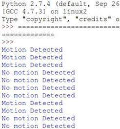
After running the Python code on the terminal, you can begin testing. If everything goes according to the project, you should be able to see the following output in the terminal:
You should be able to see the motion detection line on the terminal when any movement is detected by the PIR sensor. The advantage of using Python is that minor changes, such as changing the blinking speed or replacing LED roles, can be accomplished by simply changing the Python code without using an Arduino or an electrical circuit.
findings
A comparative analysis of the results of the practical implementation of the project by the two programming methods that we used in this work shows that the method that uses only the Arduino sketch represents the traditional programming paradigm of the microcontroller. Although this method is simpler to implement, it lacks the extensiveness achieved by the Python-Arduino interface. Thus, for practical use, we make a choice in favor of the Python-Arduino method.
Links
Source: https://habr.com/ru/post/337982/
All Articles