Overview of one Russian RTOS, part 5. First application
The next publication of the review of features of the MAKS RTOS is ready. In the previous article, we dealt with theory, and today it is time to practice.
Part 1. General information
Part 2. Core MAX MAX
Part 3. The structure of the simplest program
Part 4. Useful theory
Part 5. First Attachment (this article)
Part 6. Thread synchronization tools
Part 7. Means of data exchange between tasks
Part 8. Work with interruptions
When you start working with controllers, it is customary to blink the LEDs. I will break this tradition.
')
First, it is corny tired. Secondly, LEDs consume too much current. Do not rush to think that I save every milliwatt, just in the course of work, this saving will be extremely important to us. Again, what we will see below is almost impossible to see on LEDs.
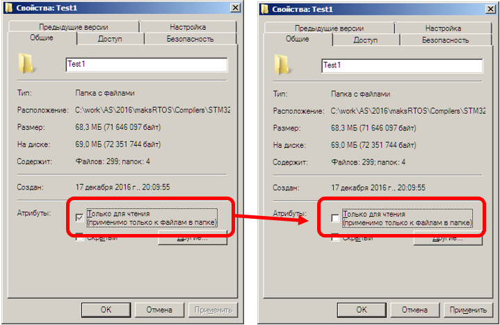
So, while there is no project generator, we take the default project for our prototype board and my favorite compiler (I took ... \ maksRTOS \ Compilers \ STM32F4xx \ MDK-ARM 5 \ Projects \ Default) and copy it under a different name (I did it ... \ maksRTOS \ Compilers \ STM32F4xx \ MDK-ARM 5 \ Projects \ Test1) . Also read-only attribute should be removed from all files.
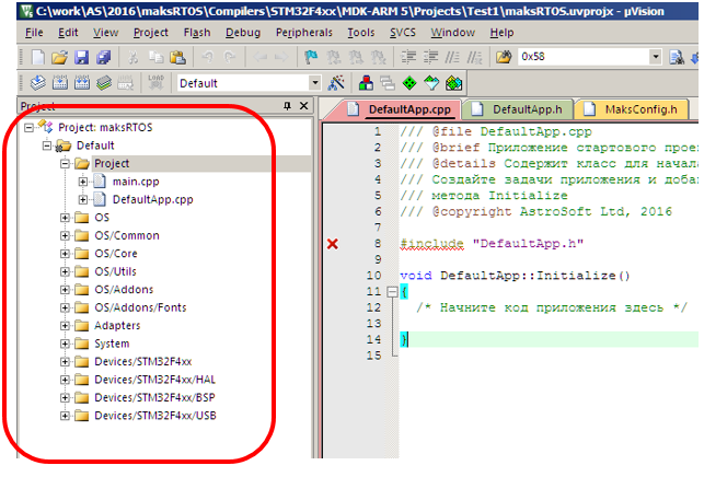
The project file directory is quite spartan.
DefaultApp.cpp
DefaultApp.h
main.cpp
MaksConfig.h
The file main.cpp refers to the canonical example, the files DefaultApp.cpp and DefaultApp.h describe the empty class derived from Application. We will use the file MaksConfig.h to change the system options.
If you open a project, it turns out that a huge number of operating system files are connected to it.
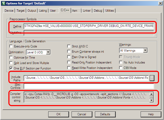
In the properties of the project also has a rabid number of settings.
So you should not even hope to create a project from scratch. We'll have to accept the fact that it should be either copied from the empty project by default, or created using automatic utilities.
For further discussion, I am torn between "correct" and "readable." The fact is that it is right to start creating files for tasks, and a separate header file, separately a file with a code. However, the reader will be confused in what the author will do. This approach is good at creating video tutorials. Therefore, I will go another way - I will start adding new classes to the DefaultApp.h file. This is fundamentally wrong in practical work, but the code will be more or less readable in the document.
So. We will not blink the LEDs. We will change the state of a pair of pins of the controller, and observe the results on an oscilloscope.
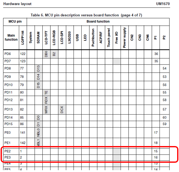
Let's make a class of a task which is engaged in this movement. We do not know how to use drivers yet, so we will turn to ports in the old manner. Choose a couple of free ports on the board. Let it be PE2 and PE3. That they are free, I derived from the following table contained in the description of the STM32F429-DISCO board:
First, we will make a class that moves PE2 with its foot, then we will remake it into a patterned look.
Go to the DefaultApp.h file (as we remember, this is wrong for real work, but clearly for the text) and create a class that inherits from Task. What should I add? That's right, the constructor and the execute () function. Fine, we write (the first and last lines are left as reference, so that it is clear exactly where we are writing):
The task jerking PE2 is ready. But now it is necessary
Where is it most convenient to do? That's right, we already know that this is most conveniently done in the function
the blessing preparation is already available. We write something like this:
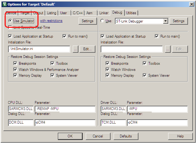
We sew in the plan ... Oh, and the project uses the default simulator.
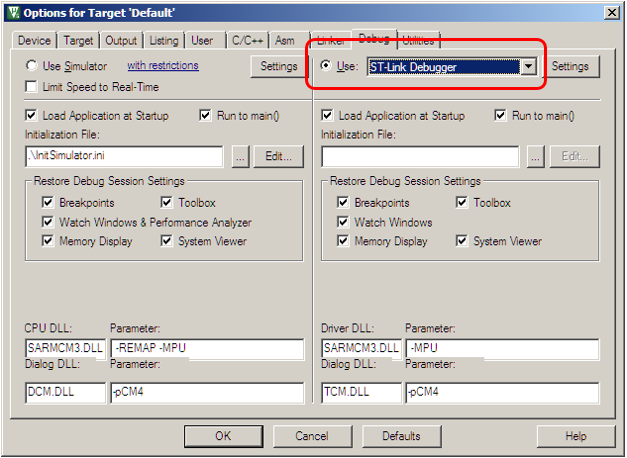
Well, we are switching to JTAG adapter (in case of STM32F429-DISCO card - to ST-Link).
Now everything can be poured into the board. Fill, connect the oscilloscope to the PE2 line, observe ...
Beauty! Only some low-speed performance.
Replacing optimization from level 0 to level 3

And ... Everything stops working altogether

Trying to trace - works fine in steps. What a miracle? Well, these are not OS problems, these are microcontroller problems, he doesn’t like the nearby commands to write to the port. The key to this effect is in the output current settings of the transistors. Higher current - more ringing, but higher speed. By default, all outputs are configured for minimum speed. And our optimizer has cleared everything up well:
You can, of course, raise the output speed at the port configuration stage
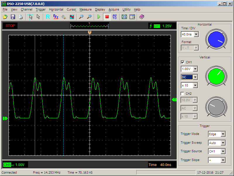
But the signal will obviously have the wrong porosity (Up, then down, then the transition delay). To improve the signal, correct the code of the main loop as follows:
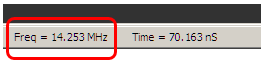
Here it turns up, then a delay at the NOP, then a down, then a transition delay, which provides a duty cycle close to 50% (in the comments below it was precisely calculated that there are actually 3 clocks in the unit and 5 clocks in zero, but this closer to 50% than 1 to 5, and on the existing oscilloscope the difference in the upper and lower parts of the pulses is still almost impossible to notice). And the output speed is already enough even in low-noise mode. The output frequency was 168 / (3 + 5) = 21 MHz.
True, on a different scale, no, no, yes, and such black holes will slip through
This we observe the work of the scheduler. We have one task, but periodically they take control from her to check whether it is possible to transfer it to someone else. If there are no other tasks, control is returned to the only one that is. Well, add the second task, which will pull PE3. Place the bit number in the member variable of the class, and configure it through the constructor
And adding tasks to the scheduler is like this:
Connect the second channel of the oscilloscope to the output PE3. Now sometimes there are pulses on one channel.
Oh, what a low frequency ... No, false start. Rewrite the task on the templates ...

And its planning statement is like this:

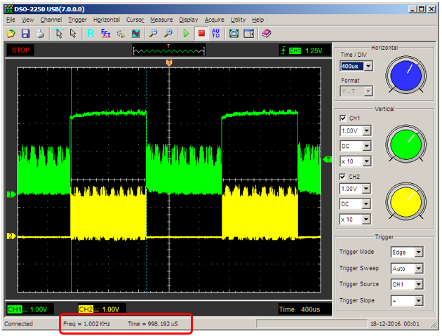
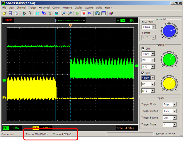
So. Now, sometimes pulses (with the correct frequency) go on the same channel:
And sometimes - on the other.
You can select the scale on which time slices are visible. At the same time, we measure and make sure that one quantum is indeed equal to one millisecond (up to the scale of the oscilloscope screen)
You can make sure that the scheduler still needs time to switch tasks (and more than at the time when there was one task)
Now let's consider the work of threads with different priorities. Add a fun task that “goes out, goes out”
And add it to the higher priority scheduler.

This task takes half the time to delay without context switching. Since its priority is higher than the others, control will not be transferred to anyone else. Half the time task is asleep. That is, it is in a locked state. That is, threads with normal priority will work at this time. Check?
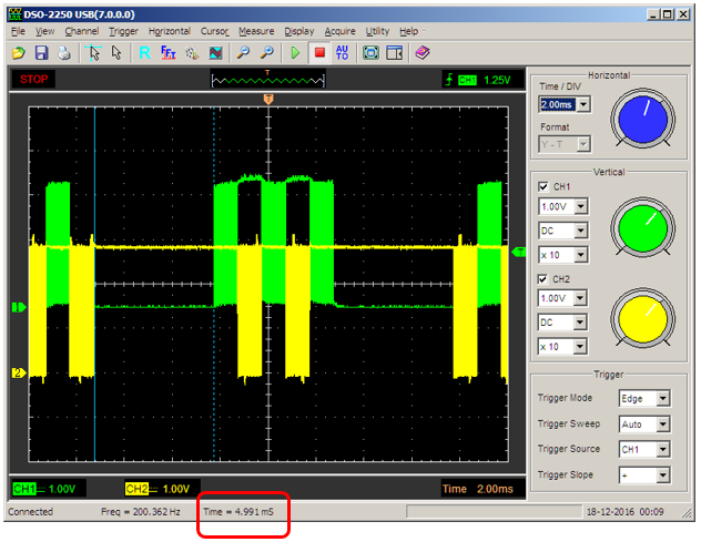
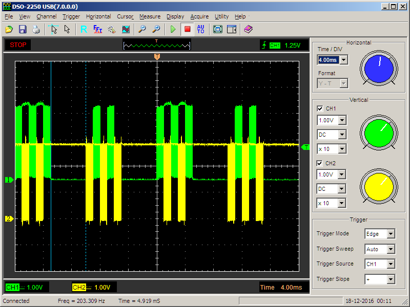
Actually, what was required to prove. The pause is equal to five milliseconds (highlighted by cursors), and during normal tasks, the context has time to switch between them. Here is another scale so that it can be seen that this is not an accident, but statistics
We remove the work of this terrible task. We will continue with the two main
Task :: Add (new Blinker <2> ("Blink_PE2"));
Task :: Add (new Blinker <3> ("Blink_PE3"));
Finally, we will translate the port pulling from the “Very puffy” mode to the more real one. To LED will not bring. Let's say we make a period of 10 milliseconds

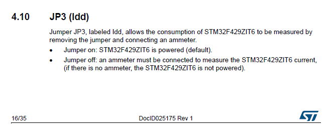
Teprer connect ammeter. For the STM32F429-DISCO board, remove jumper JP3 and turn on the device instead of it, as stated in the documentation:
We measure the current consumed by this version of the program.
Go to the file MaksConfig.h and add the line there:
#define MAKS_SLEEP_ON_IDLE 1
We put together a project, “flashing” the result into the board, look at the ammeter:

Soooo, another theoretical thing checked in practice. It works too. But if we blinked with a LED, then it would consume, then not consume 10 mA, which is quite significant against the background of the measured values.
Well, and finally, replace the multi-tasking cooperative. To do this, add a constructor to the application class.
And we will make sure that tasks after three pulses to the port transfer control to each other. We will also add delays so that the delay on the oscilloscope doesn’t take the image of another task behind the screen.
What is there on the oscilloscope?
Actually, we wanted triples of impulses - we received them.
Well, finally, let's add a virtual function.
and try to cause any problem. For example, create a critical section in a task with a normal level of privileges.
We start the project for debugging, put a breakpoint on the next line

after which we launch for execution (F5). Instantly we get a stop (if it doesn't work, click on the “Stop” icon).
In the line where the break occurred, we move the cursor to the variable reason. We get the following result:

Well, we have completed the verification of the first basic theoretical calculations; we can proceed to the next large complex section .
Part 1. General information
Part 2. Core MAX MAX
Part 3. The structure of the simplest program
Part 4. Useful theory
Part 5. First Attachment (this article)
Part 6. Thread synchronization tools
Part 7. Means of data exchange between tasks
Part 8. Work with interruptions
When you start working with controllers, it is customary to blink the LEDs. I will break this tradition.
')
First, it is corny tired. Secondly, LEDs consume too much current. Do not rush to think that I save every milliwatt, just in the course of work, this saving will be extremely important to us. Again, what we will see below is almost impossible to see on LEDs.
So, while there is no project generator, we take the default project for our prototype board and my favorite compiler (I took ... \ maksRTOS \ Compilers \ STM32F4xx \ MDK-ARM 5 \ Projects \ Default) and copy it under a different name (I did it ... \ maksRTOS \ Compilers \ STM32F4xx \ MDK-ARM 5 \ Projects \ Test1) . Also read-only attribute should be removed from all files.
The project file directory is quite spartan.
DefaultApp.cpp
DefaultApp.h
main.cpp
MaksConfig.h
The file main.cpp refers to the canonical example, the files DefaultApp.cpp and DefaultApp.h describe the empty class derived from Application. We will use the file MaksConfig.h to change the system options.
If you open a project, it turns out that a huge number of operating system files are connected to it.
In the properties of the project also has a rabid number of settings.
So you should not even hope to create a project from scratch. We'll have to accept the fact that it should be either copied from the empty project by default, or created using automatic utilities.
For further discussion, I am torn between "correct" and "readable." The fact is that it is right to start creating files for tasks, and a separate header file, separately a file with a code. However, the reader will be confused in what the author will do. This approach is good at creating video tutorials. Therefore, I will go another way - I will start adding new classes to the DefaultApp.h file. This is fundamentally wrong in practical work, but the code will be more or less readable in the document.
So. We will not blink the LEDs. We will change the state of a pair of pins of the controller, and observe the results on an oscilloscope.
Let's make a class of a task which is engaged in this movement. We do not know how to use drivers yet, so we will turn to ports in the old manner. Choose a couple of free ports on the board. Let it be PE2 and PE3. That they are free, I derived from the following table contained in the description of the STM32F429-DISCO board:
First, we will make a class that moves PE2 with its foot, then we will remake it into a patterned look.
Go to the DefaultApp.h file (as we remember, this is wrong for real work, but clearly for the text) and create a class that inherits from Task. What should I add? That's right, the constructor and the execute () function. Fine, we write (the first and last lines are left as reference, so that it is clear exactly where we are writing):
#include "maksRTOS.h" class Blinker : public Task { public: Blinker (const char * name = nullptr) : Task (name){} virtual void Execute() { while (true) { GPIOE->BSRR = (1<<2); GPIOE->BSRR = (1<<(2+16)); } } }; class DefaultApp : public Application The task jerking PE2 is ready. But now it is necessary
- Enable port E clocking;
- Connect the task to the scheduler.
Where is it most convenient to do? That's right, we already know that this is most conveniently done in the function
void DefaultApp::Initialize()the blessing preparation is already available. We write something like this:
void DefaultApp::Initialize() { /* */ // E RCC->AHB1ENR |= RCC_AHB1ENR_GPIOEEN; // PE2 PE3 GPIOE->MODER = GPIO_MODER_MODER2_0 | GPIO_MODER_MODER3_0; // Task::Add (new Blinker ("Blink_PE2")); } We sew in the plan ... Oh, and the project uses the default simulator.
Well, we are switching to JTAG adapter (in case of STM32F429-DISCO card - to ST-Link).
Now everything can be poured into the board. Fill, connect the oscilloscope to the PE2 line, observe ...
Beauty! Only some low-speed performance.
Replacing optimization from level 0 to level 3
And ... Everything stops working altogether
Trying to trace - works fine in steps. What a miracle? Well, these are not OS problems, these are microcontroller problems, he doesn’t like the nearby commands to write to the port. The key to this effect is in the output current settings of the transistors. Higher current - more ringing, but higher speed. By default, all outputs are configured for minimum speed. And our optimizer has cleared everything up well:
0x08004092 6182 STR r2,[r0,#0x18]
0x08004094 6181 STR r1,[r0,#0x18]
0x08004096 E7FC B 0x08004092
You can, of course, raise the output speed at the port configuration stage
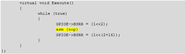
// GPIOE->OSPEEDR |= (3<<(2*2))|(3<<(3*2)); But the signal will obviously have the wrong porosity (Up, then down, then the transition delay). To improve the signal, correct the code of the main loop as follows:
same text
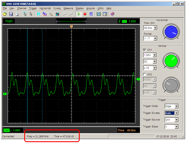
virtual void Execute() { while (true) { GPIOE->BSRR = (1<<2); asm {nop} GPIOE->BSRR = (1<<(2+16)); } } }; Here it turns up, then a delay at the NOP, then a down, then a transition delay, which provides a duty cycle close to 50% (in the comments below it was precisely calculated that there are actually 3 clocks in the unit and 5 clocks in zero, but this closer to 50% than 1 to 5, and on the existing oscilloscope the difference in the upper and lower parts of the pulses is still almost impossible to notice). And the output speed is already enough even in low-noise mode. The output frequency was 168 / (3 + 5) = 21 MHz.
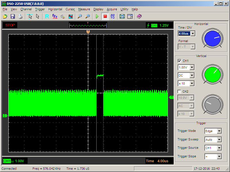
True, on a different scale, no, no, yes, and such black holes will slip through
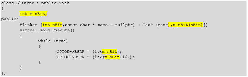
This we observe the work of the scheduler. We have one task, but periodically they take control from her to check whether it is possible to transfer it to someone else. If there are no other tasks, control is returned to the only one that is. Well, add the second task, which will pull PE3. Place the bit number in the member variable of the class, and configure it through the constructor
Text
class Blinker : public Task { int m_nBit; public: Blinker (int nBit,const char * name = nullptr) : Task (name),m_nBit(nBit){} virtual void Execute() { while (true) { GPIOE->BSRR = (1<<m_nBit); GPIOE->BSRR = (1<<(m_nBit+16)); } } }; And adding tasks to the scheduler is like this:
Text
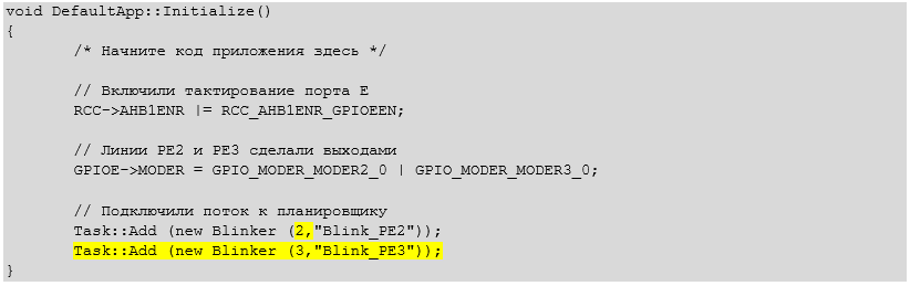
void DefaultApp::Initialize() { /* */ // E RCC->AHB1ENR |= RCC_AHB1ENR_GPIOEEN; // PE2 PE3 GPIOE->MODER = GPIO_MODER_MODER2_0 | GPIO_MODER_MODER3_0; // Task::Add (new Blinker (2,"Blink_PE2")); Task::Add (new Blinker (3,"Blink_PE3")); } Connect the second channel of the oscilloscope to the output PE3. Now sometimes there are pulses on one channel.
Oh, what a low frequency ... No, false start. Rewrite the task on the templates ...
Text
template <int nBit> class Blinker : public Task { public: Blinker (const char * name = nullptr) : Task (name){} virtual void Execute() { while (true) { GPIOE->BSRR = (1<<nBit); asm {nop} GPIOE->BSRR = (1<<(nBit+16)); } } }; And its planning statement is like this:
Text
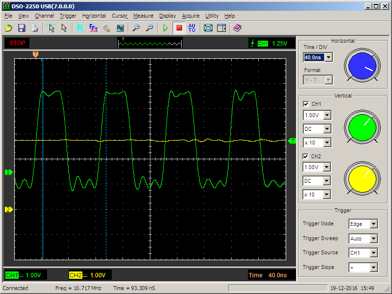
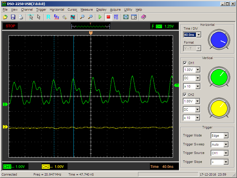
Task::Add (new Blinker<2> ("Blink_PE2")); Task::Add (new Blinker<3> ("Blink_PE3")); So. Now, sometimes pulses (with the correct frequency) go on the same channel:
And sometimes - on the other.
You can select the scale on which time slices are visible. At the same time, we measure and make sure that one quantum is indeed equal to one millisecond (up to the scale of the oscilloscope screen)
You can make sure that the scheduler still needs time to switch tasks (and more than at the time when there was one task)
Now let's consider the work of threads with different priorities. Add a fun task that “goes out, goes out”
public: Funny (const char * name = nullptr) : Task (name){} virtual void Execute() { while (true) { Delay (5); CpuDelay (5); } } }; And add it to the higher priority scheduler.
Text
Task::Add (new Blinker<2> ("Blink_PE2")); Task::Add (new Blinker<3> ("Blink_PE3")); Task::Add (new Funny ("FunnyTask"),Task::PriorityHigh); This task takes half the time to delay without context switching. Since its priority is higher than the others, control will not be transferred to anyone else. Half the time task is asleep. That is, it is in a locked state. That is, threads with normal priority will work at this time. Check?
Actually, what was required to prove. The pause is equal to five milliseconds (highlighted by cursors), and during normal tasks, the context has time to switch between them. Here is another scale so that it can be seen that this is not an accident, but statistics
We remove the work of this terrible task. We will continue with the two main
Task :: Add (new Blinker <2> ("Blink_PE2"));
Task :: Add (new Blinker <3> ("Blink_PE3"));
Finally, we will translate the port pulling from the “Very puffy” mode to the more real one. To LED will not bring. Let's say we make a period of 10 milliseconds
Text
class Blinker : public Task { public: Blinker (const char * name = nullptr) : Task (name){} virtual void Execute() { while (true) { GPIOE->BSRR = (1<<nBit); Delay (5); GPIOE->BSRR = (1<<(nBit+16)); Delay (5); } } }; Teprer connect ammeter. For the STM32F429-DISCO board, remove jumper JP3 and turn on the device instead of it, as stated in the documentation:
We measure the current consumed by this version of the program.
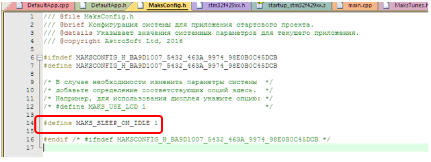
Go to the file MaksConfig.h and add the line there:
#define MAKS_SLEEP_ON_IDLE 1
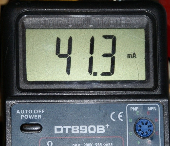
We put together a project, “flashing” the result into the board, look at the ammeter:
Soooo, another theoretical thing checked in practice. It works too. But if we blinked with a LED, then it would consume, then not consume 10 mA, which is quite significant against the background of the measured values.
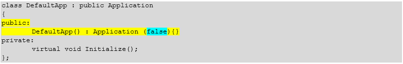
Well, and finally, replace the multi-tasking cooperative. To do this, add a constructor to the application class.
Text
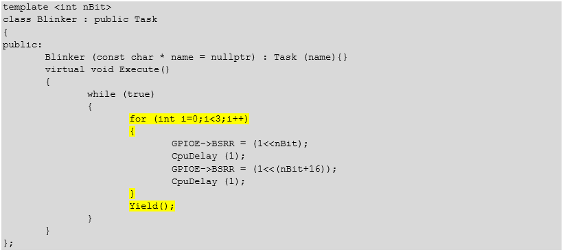
class DefaultApp : public Application { public: DefaultApp() : Application (false){} private: virtual void Initialize(); }; And we will make sure that tasks after three pulses to the port transfer control to each other. We will also add delays so that the delay on the oscilloscope doesn’t take the image of another task behind the screen.
Text
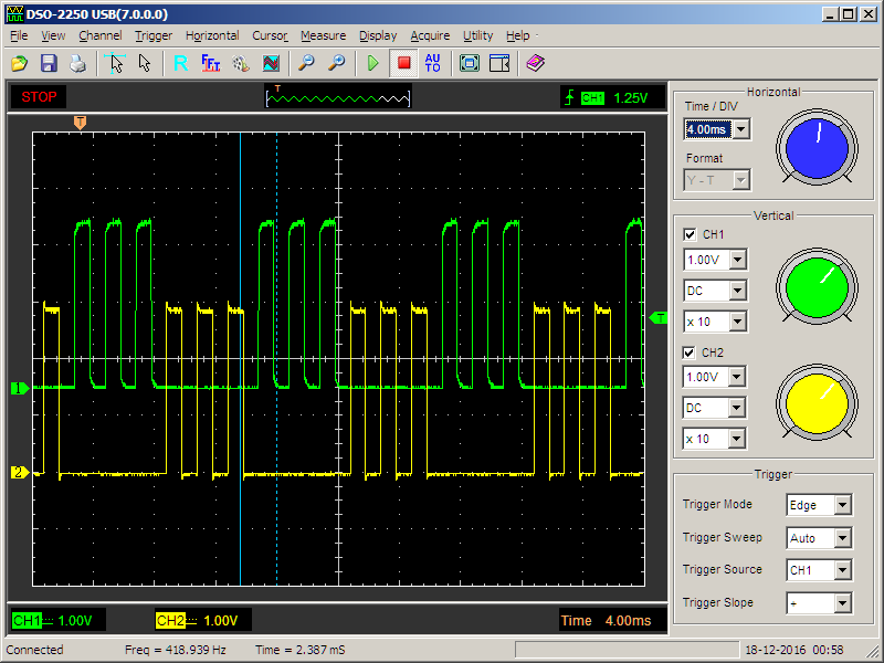
template <int nBit> class Blinker : public Task { public: Blinker (const char * name = nullptr) : Task (name){} virtual void Execute() { while (true) { for (int i=0;i<3;i++) { GPIOE->BSRR = (1<<nBit); CpuDelay (1); GPIOE->BSRR = (1<<(nBit+16)); CpuDelay (1); } Yield(); } } }; What is there on the oscilloscope?
Actually, we wanted triples of impulses - we received them.
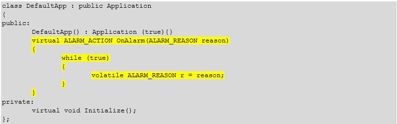
Well, finally, let's add a virtual function.
Text
class DefaultApp : public Application { public: DefaultApp() : Application (true){} virtual ALARM_ACTION OnAlarm(ALARM_REASON reason) { while (true) { volatile ALARM_REASON r = reason; } } private: virtual void Initialize(); }; and try to cause any problem. For example, create a critical section in a task with a normal level of privileges.
Blinker (const char * name = nullptr) : Task (name){} virtual void Execute() { CriticalSection cs; while (true) { GPIOE->BSRR = (1<<nBit); Delay (5); GPIOE->BSRR = (1<<(nBit+16)); Delay (5); } We start the project for debugging, put a breakpoint on the next line
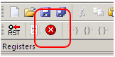
after which we launch for execution (F5). Instantly we get a stop (if it doesn't work, click on the “Stop” icon).
In the line where the break occurred, we move the cursor to the variable reason. We get the following result:
Well, we have completed the verification of the first basic theoretical calculations; we can proceed to the next large complex section .
Source: https://habr.com/ru/post/337974/
All Articles