The practice of forming requirements in IT projects from A to Z. Part 6. System behavior. Excellence requirements
All parts
Part 1. Introduction
Part 2. Goals and Needs
Part 3. System Functions and Project Boundaries
Part 4. Business processes automated by the system.
Part 5. Essence of the subject area and a little about strategies
Part 6. Behavior of the system. Excellence requirements
Part 7. The transfer of requirements in production. Conclusion
IX Definition of system behavior.
In many cases, the behavior ... only because it seems ridiculous that the reasons for it, quite reasonable and solid, are hidden from others.
Francois de Larochefuca
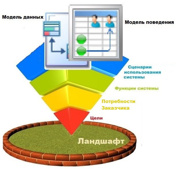
Once we have decided on the list of main scenarios and entities of the domain, it is necessary to compare them with each other.
The purpose of this group of works: on the basis of the identified entities and processes of the target product being developed, to design the behavior of the system, distributing it into classes.
This process is conveniently performed using a canonical sequence diagram. On diagrams of this type, you can model chains of events in which one object, using processes, transmits a message to another object and forces it in turn to respond to this incident. As a result of such an event, the requested object may return a response, or initiate the following processes. Thus, it is convenient to formalize the low-level functions of the system. The longer and more complex the chain of reactions to an event, the harder it is to do without using a sequence diagram.
')
Figure 9.1 depicts the process of formalizing the requirements for the target system, supplemented by a subprocess of determining its behavior.
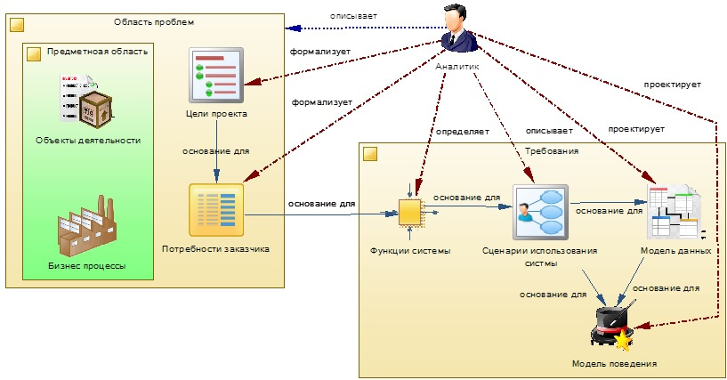
Figure 9.1 - model of the system behavior determination process
1. Use sequence diagrams to simulate system behavior.
Let's continue the design of the “Task accounting” contour and analyze as an example the system behavior when assigning tasks to performers, see Figure 9.2
Let me remind you that the sequence diagrams are read from left to right, top to bottom.

Fig. 9.2 - Sequence Diagram Formation of Tasks
This operation begins with the selection of a pre-developed Task Map Template (hereinafter referred to as SCR), on the basis of which a new activity will be formed in the project, in the form of a Task Map to users. Please note that the instance of the Task Map in the diagram is not located in the top row, but only at the level of the arrow of the event that actually generates it in the process under consideration. But we ran a little ahead. Let's go back to our diagram and continue to look at it sequentially (also known as a sequence diagram).
On the class diagram (discussed in the last part of the article), see Figure 8.4, it is clear that the SHKZ uses the reference to the Directory of Full-time Positions. It is necessary to identify the person responsible for the execution of the Task Map. Therefore, by the second step of the scenario, we determine the specific Employee currently occupying the position by the standard position. By the way, having mentioned the second step I noticed an oversight, there are no numbers on my diagram near the arrows, they are usually put down and it is very convenient. So, the employee identified by us at the second step will be the curator of the job card. In fact, at this stage of modeling, we formalized a new system function (not to be confused with the business functions discussed in our previous sections), to the input of which the Established position is applied, and the output returns a link to the employee. Most likely this function will be useful to us more than once.
We go further, as was emphasized earlier - from top to bottom, from left to right. SHKZ associates task templates, defining the composition and sequence of operations for performers. Therefore, in the same way as we created the Task Map using the SKKZ, we create by the Task Templates - Tasks (operations), combined into the Task Map just created. But since there can be many Tasks in one Map, we use a cycle simulation method in a diagram (frame with a loop stereotype). Similarly, diagrams of this type can be shown: conditional transitions, preconditions and other conditional constructions.
For the Task Template, as well as for the SHKZ, a reference to the reference book of the full-time positions is defined. This link is necessary to determine the already direct performer of the Task, which is included in the Map. For each assignment for this link we define the artist (if possible). It is not difficult to notice that this function has already been identified and identified by us in the second step of the diagram.
Another important process in this example: filling in the parameters that determine the characteristics of the Task. During the formation of the Task, the parameters that are defined for its Template as incoming are filled with the current values of the system entities. This process is shown abstractly through the abstract class "Metadata". For a more detailed definition of the steps of this process, a separate diagram is constructed.
Thus, by modeling the processes in the sequence diagrams, step by step, we determine the system functions that need to be implemented in the program code, their input and output parameters, as well as execution sequences.
Sequence diagrams are especially useful in systems saturated with trigger constructions, in which the chain changes the objects sequentially and automatically one after the other. In long chains, it can turn out that one and the same object changes by different trigger procedures and it is sometimes problematic to track the final result without modeling.
2. We analyze the change in the state of objects when modeling the behavior of the system
To implement the requirements of event-driven systems, special requirements are placed on the definition and management of states (a set of properties at a particular point in time) of objects, when various events occur. For example, the development of a script to automatically change the properties of an object when certain conditions occur, at a certain point in time. Such problems are conveniently modeled using canonical state diagrams, which allow to associate events with states. This type of diagram can be effectively used in conjunction with sequence diagrams that clearly detect events.
I recall the basic postulates of modeling using state diagrams. The main element of the state diagram is naturally the “state” of the object under consideration. In one diagram, it is possible to simulate state transitions of only one object. One state on the diagram can occur only once.
Below in Figure 9.3 there is an example of modeling state transitions of the “Task” object. On the diagrams of this type there is always an element that defines the production of an object and indicates the beginning of its life cycle (hereinafter referred to as LC). In our case, when creating a new Task, the critical attribute that determines its next state will be the executor. If it is set, the task can be proposed for execution; if not, it will continue to remain in the initial state. In this example, the rules for filling the remaining attributes of the object (which can also occur) are not considered, since they are not significant for us in a particular case.
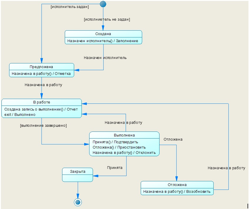
Fig. 9.3 - Task Status Chart
The diagram in square brackets, next to the arrow, indicates the transition conditions. They indicate that if this condition is fulfilled, the transition to the next one in the arrow will be made. And the inscription near the arrow without the brackets denotes the event on which the state change should be performed. In the rectangle denoting the state, all possible events are listed that cause the transition (they must correspond to the events on the arrows). Each state in the diagram must necessarily get an arrow (s) to go into it and one or more arrows to go out of it. Thus, it is very difficult to lose sight of any events and transition conditions.
For example, the “Completed” state can be reached from the “In Work” state, provided that a check mark is displayed. And from it you can go to the state:
- “Closed”, if the report is accepted and confirmed,
- “Delayed” if the decision is made to suspend the task
- return to the “In Work” state if the implementation report is not accepted and the task needs further work.
On the diagram, the end of the life cycle of the object must always be determined.
In practice, instead of state diagrams, it is sometimes convenient to use state transition tables. They are clearer for most project stakeholders and are used in cases where there are no complicated, complicated processes. For example, the following is a simplified table of the transition of Task States in the project we are considering.
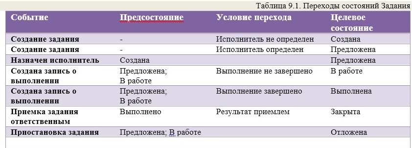
But when compiling the tables, it should be understood that there is a high probability of missing something important. Therefore, it is better to carry out modeling using diagrams, and then, based on them, fill in the table. For example, to be honest, I first compiled a table and did not plan to include a drawing with a diagram in this chapter, leaving it up to you at your discretion. But having changed my decision, I immediately found many inconsistencies, and you can see them yourself, since I didn’t specifically fix anything.
3. Avoid unnecessary “out-of-administration” of the system.
When designing mechanisms that allow, on the basis of the data recorded in the system, to decide on the way they are processed, special attention should be paid to the likelihood that the rules for forming the conditions for choosing these decisions may change. I will explain it more simply: if the customer says that a certain rule always works, this does not mean at all that after the introduction of the system, there is no objective reason to add an exception to this “reinforced concrete” rule. A rigidly designed decision-making mechanism, in this case, will be a big headache for all project participants.
In my practice there was a project aimed at creating a system for automating customer relationships, including sales. The developed system was supposed to replace the outdated one, in which the records were kept in manual mode (but naturally, according to certain rules). Approved regulatory documents were established for the design, which set the rules for sales at the company. Based on the documents, a mechanism has been developed that allows the system to be flexibly configured to handle these rules. But when introducing a system that could automatically generate invoices using a complex multi-level discount system, it turned out that there are cases when sales occur without any rules at the discretion of managers, and the software developed doesn’t allow doing this. In order to redesign the system for the possibility of billing "from the lamp", we had to make more changes. With this example, I wanted to emphasize that too complex encapsulation leads to a decrease in manageability and narrows the applicability of the module. This has already been mentioned in Chapter VIII.
Therefore, in such cases, it is advisable to use the following recommendations:
- when defining values to select a processing rule, use constants that the user can easily change if necessary;
- consider the “rollback” mode - cancellation of operations (transactions) performed by the system based on the decision-making mechanism;
- Perform granulation processes, dividing complex ones into simple ones, distributing responsibility among the objects connected with each other by simple interfaces. In this case, it will be easier to make changes in the behavior of decision-making subsystems, or to replace them with new subsystems and services;
For example, in the assignment module for performers, the following processes are carried out according to the template:
- Formed Task Map and Tasks on the template;
- Performers are notified of the task assigned to them.
It would be possible to create one object that sequentially performs these two processes. But there is a possibility that over time, it will be necessary to notify the executors of the assignment of the task not all at once, but successively as the previous tasks are completed. In this case, the division of responsibility between the two objects will allow: the first object to be responsible only for the formation of tasks, and the second one with a certain frequency to notify the executors of the assignment, as they “mature” for execution.
X Improving requirements
I, in my practice, use the method of forming requirements in several passes. That is, at first I throw in a draft version, not trying to immediately get high-quality formulations. In descriptions words can be repeated, expressions can be “clumsy”, etc. The main thing is to state the main ideas, and to form a related structure - the framework of specifications. Later, I read the specifications again and try to “brush” the text so that it is well perceived by the ear. Sometimes the descriptions change beyond recognition. So I go through the specifications 4-5 times (and sometimes more), until they turn into a slender and easily perceived structure. By the way, this publication was written in the same way.
The purpose of this group of works: to normalize the form of requirements, making it as simple as possible for perception and convenient to use.
1. Check the traceability of requirements
As noted above, it is very important to maintain communication between all project artifacts, starting from the earliest stages. We, in our project, going to each subsequent stage, used the artifacts from the previous one, clearly indicating the links. Thus, for example, according to the User History, you can easily select the requirements specifications, determine the tasks to be performed and the degree of their execution.
For traceability artifacts use identifiers in them. Put in artifacts links to identifiers of other artifacts. Based on these relationships, you can track requirements that are not related to other requirements, User stories, other artifacts and once again analyze the feasibility of using them or determine gaps in the completeness of requirements.
2. We work on testability
By making up the requirements, you should take care of all team members who will use them, making the specifications as useful as possible for them.
From the point of view of testability, attention should be paid to the fact that the requirement must contain an exact test criterion. That is, it should allow to unequivocally answer the question: “does the requirement satisfy the wishes of the customer or not”.
Forming requirements, try to make them in such a way that on the basis of them it was easy and convenient to develop acceptance tests. The criteria should allow to verify both the completeness and the accuracy of the implementation. Such techniques are very effectively used in the methodology of flexible design Scrum, XP [10]. Use, for example, the formation of explanations in the text of the requirements, displaying the rules for filling data with an indication of options that are the boundary for the choice of processing algorithm. For example, you can create a table in one of the columns of which lists the values that are boundary for the choice of the behavior algorithm, and in the other indicate how the system should behave in this case. For example:
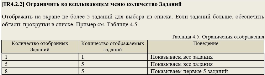
When compiling acceptance tests, the tester uses the already prepared values.
Well, in any book that teaches the process of developing requirements, you can read that in terms of testability, you need to pay attention to such characteristics of the requirements as:
- Clarity (unambiguity, certainty, unambiguity);
- Feasibility (feasibility by performers);
- Completeness (the text of the requirement does not need additional detailing for performers);
- Unity (the requirement should describe one and only one “thing”);
- Consistency (the requirement should not contradict other requirements);
3. Agree on requirements
The main effect of the simulation is achieved by identifying in the early stages of design a discrepancy between the idea of the resulting product between the customer and the developers. Sometimes, it allows to achieve understanding and within the development team. The modeling also allows users to more clearly, in detail, present some of their assumptions about the functioning of the product and make clarifications or changes to the original wishes. The better this process goes, the less it will be necessary to make changes to an already realized product. Therefore, the coordination of requirements with customers is a very important point, which should not be missed, and, moreover, the coordination should be made at regular intervals after each significant progress of the project.
I myself have repeatedly read such recommendations, and for the most part I ignored them until it touched me personally. Somehow, everything went quite smoothly, and sometimes they took projects with insufficiently elaborated requirements, and modified them during the course of development, and got away with it all the time. But sooner or later there comes a time when you relax, caution gradually dulled, a partner or customer is required, who, on the basis of poorly formalized, but very budgetary agreements about one, will require you to do something completely different and will twist your arms and lead you to despair. And God forbid, it will be the state structure - you are "hit" ... It is better not to bring this up.
Do not be afraid of all diagrams, diagrams, specifications related to the description of business processes, show to the customer. And not just to show, but to explain their content in such a way that he would have questions, and an interest in discussion arose. This is a difficult and painstaking process, and it will not work out right away.
You should gradually and relentlessly accustom the customer to listen to your explanations and delve into the essence of the presented documents. Decide on the composition of the charts that are best perceived by them.
Very often, after seeing the first prototypes of the product, the user changes his primary wishes. And since, in this case, the requirements have already been formally approved by the project participants, amending them should go through a separate, more stringent approval procedure. After all, these changes may affect related processes or functionality of other users.
The mechanism for changing requirements is described in more detail in the chapter “Solving the problem of changing requirements”.
Coordination should be made not only in terms of the requirements, but also in the priority of their implementation. For this, the team, together with the customer, defines such a characteristic as the “Importance” of the requirement.
4. Determine the risks of the requirements development process.
Let's skip working with risks in the project “in general”, and touch only on the topic of risk management when developing requirements. As noted above, the modeling method itself reduces the risk of developing unnecessary or incorrect functionality in a product. This is due to the fact that in the early stages of design, designers and developers can discuss with the customer the functionality on the prototype models of the product. Accordingly, the more qualitatively the models are developed, the greater the understanding of the subject area can be achieved in the course of such discussions. Conversely, if you do not have enough time to develop high-quality, deep requirements, then you risk creating a product that does not satisfy the needs of the customer. This will become clear after it has been developed, will require additional costs, which can greatly upset the customer.
In the case when in the early stages it is impossible to determine the complexity and feasibility of the designed functions, it is necessary to develop alternative options, albeit less effective, but more predictable. This will allow, in case of failure with the main implementation option, to quickly switch to an alternative one. It will also allow the team to inform about the possibility of risk and it will not come as a surprise to difficulties with implementation.
In general, the risks associated with the requirements are mainly due to the deviation of one of its characteristics from the norm. It:
- Consistency of requirements among themselves;
- Unambiguous interpretation;
- Definition of Testability criteria;
- Coordination with the customer and interested parties;
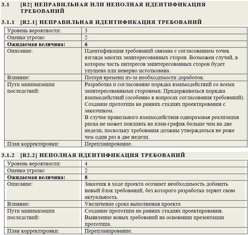
Documented risks are usually documented in a separate document and are the responsibility of the project manager, so we’ll not separately focus on this. I’ll show you how it may look in the document.
The next part we devote to the specification of the requirements link .
Bibliography
1. Jacobson A., Butch G., Rambo J. - “Unified Software Development Process” (2004)
2. David A. Mark and Clement McGowan - “SADT Structural Analysis and Design Methodology”
3. Coburn - "Modern methods for describing functional requirements" (2002)
4. Leffingwell Dean, Widrich Don - “Principles of working with software requirements” (2002)
5. Karl I. Wigers - “Developing Software Requirements” (2002)
6. Elizabeth Hull, Ken Jackson, Jeremy Dick - “Developing and Managing Requirements A Practical User Guide” (2005)
7. Scott Ambler - “Flexible Technologies: Extreme Programming and a Unified Development Process” (2005)
8. Greenfield Jack, Kane Short - "Software Development Factories" (2007)
9. Alistair Cowburn - “Each project has its own methodology”
10. Wolfson Boris - “Flexible development methodologies”
11. Leszek A. - “Requirements Analysis and System Design”
12. Freeman Eric, Freeman Elizabeth - “Design Patterns” (2011)
13. Evans Erik - “Subject-Oriented Design” (2011)
14. GOST 34.602-89 “Information technology. Set of standards for automated systems. Terms of Reference for the creation of an automated system "
Source: https://habr.com/ru/post/337678/
All Articles