How to resurrect a jaguar for a thousand hours?
 Sometimes people ask me - how do I write emulators? I will try to answer the example of one failed console.
Emulation is almost endless, there are always inaccuracies, and if they ask me how much I spent on 3DO emulation, then I just shrug, but I know one thing for sure - everything is very good with 3DO emulation. Therefore, it is time to find a new victim and it turned out to be Atari Jaguar. 1000 hours - approximately as much I spent on the development of the emulation kernel of this console in the Phoenix project , and it will probably take as much again to increase compatibility from the current 95% to 99%, and the remaining 1% will require more, perhaps more than one thousand hours, but these are separate boring stories about debugging subtle glitches.

')
Why precisely Jaguar? Firstly, it was poorly emulated by existing emulators. Secondly, it is well “documented”, there are specifications, circuit diagrams and even HDL codes of its chips !
The first stage - collecting information about the enemy (300 hours)
The image below shows a simplified action plan for collecting the primary information needed to create an emulator for your favorite game console.

This stage, as you can see, is not always limited to the word “google”, this is a full-fledged and most important development stage, this is a whole study. As for “google”, first of all I recommend to search for patents on console subsystems, datasheets on chip markings and just read the information on resources related to the technical side of the console. Further, based on the found, focus on collecting data according to the plan.
Someone rightly notes that there is another source of knowledge - other people's projects. If you want to join the project, then this is the right idea, but if not, then I do not recommend relying on a similar source of information, at least until your own release, so as not to repeat the mistakes of others. In the case of the Jaguar there is a Virtual Jaguar project, I remember I wanted to improve it, but I quickly discarded this idea as soon as I saw the code itself .
Extracting the scheme is a task that you should definitely do in the first place, because you can extract useful information about the operating modes of the elements, buses and the purpose of at least some of the outputs of the chips for which you could not find the documentation. If you can, you can make a computerized tomography of a printed circuit board, but old consoles usually have two layers and a simple multimeter is enough to plot the circuit diagram by dialing.
The search for software for the emulated platform covers both the software that is subsequently emulated (dumps - BIOS, ROM, ISO) and the development tools for this platform. The latter are especially important for creating tests that will serve to identify the internal structure of the elemental base, in addition, the results of these tests can serve in the future to test the future emulator for compliance with the real hardware. Quite often, the original SDKs are not compatible with modern OSs, so you may have to adapt these SDKs to modern compilers or even use old PC emulators to write tests. If the development tools are really bad, it makes sense to write your own assembler or even a simple compiler. Believe me, the preparation of development tools that will pay off many times over in the future will help save a lot of time.
As for the dumps, if they are not made by someone earlier, then to get the ROM, the easiest way is to drop the chip and read its contents in the programmer, which is more complicated but neat - find a way to connect the console to the computer - via the debugging interface or which port expansion and write a special program to exchange data with a PC. For example, on 3DO I connected to the JTAG ARM processor and dumped the ROM, I also connected to the factory console debug port and ran my code on it, for this I had to make a small device with a controller and FPGA.
The definition of the element base is the most important of the tasks of this stage. If you managed to find sufficiently detailed documentation on all components, then everything is fine and you can start creating an emulator, but what if among the main components you came across the real black boxes? There are several options. You can act head-on (if skills permit, time and money) —this is to open the chip, in other words, to shoot the entire chip on the microscope and restore the circuit of the device. I have never done this before, but this is a win-win solution, provided that you have enough patience or talent to automate the processing of the information obtained in this way.
Depending on the topology, it is possible to apply or combine in-circuit and off-circuit testing of black boxes. In both cases, the digital signal analyzer and the oscilloscope will not be superfluous. In-circuit testing is preferable and faster, with this approach, you write a special code that will test the device you are interested in inside the console. Suppose you are testing a video processor, based on the data in the SDK or other considerations, you make various recording options in registers and analyze the result on the screen, record the occurring interruptions and delays.
Sometimes it is difficult to determine the behavior of a component on the basis of in-circuit tests, for example, when it does not work directly with the central processor. In this case, it is reasonable to perform off-chip testing, for this you make a special printed circuit board for connecting to a PC and transfer the tested chip to it, then send signals to the inputs and read the outputs, and then everything depends on your mental abilities. The only thing is that you need to know exactly where and what the inputs and outputs are for this chip, this part can be found out by the interconnection of the components, and in especially difficult cases by cutting the tracks (I don’t recommend lifting the legs - it happens that they break). If you have solved the puzzle, it will not be superfluous to return to the place not the microchip itself, but to hook its emulation on the FPGA to finally verify the correctness of your conclusions, this is certainly not a simple procedure, but if you want to make a prefix on FPGA, you will already be hurt.
What about Jaguar? And with him everything is very cool, as I said, there are the original HDL codes of its chips , specifications and schematic diagrams. Of course, I would also like a working console, but with all of the above, you can safely say that you can do without it. Therefore, I immediately took the documentation to the printing house:
- Technical Reference Manual Tom & Jerry (this is not the heroes of the famous cartoon, but the main console chips, by the way, is a common style with 3DO, 3DO also has two main chips with interesting names - Madam & Clio, and if I remember correctly - some of the developers left the 3DO Atari);
- Motoroll M68000 Famaly Programmer's Reference Manual - the documentation for the CPU console;
- Schematic diagram of the console - it is very important to understand what interacts with what and how, without it, the console would still be necessary.
Of course, this is not all of the documentation, but only its main part, I also had to look for datasheets for all sorts of little things like EEPROM or quartz, I really, in the absence of a live console and cartridges, had to find their photographs and search the electronic components.
But the HDL code was a very tough nut to crack. It is written in Toshiba's little-known HDL, in relation to modern Verilog or VHDL, it is like an assembler in relation to C ++, scattered over a hundred files and keeping the interconnect of components in your head (at least for me) is not possible. From this code I needed to make a hum ... a "book," well, let's write a translator! I put the code on a githab (all of a sudden someone needs it), but since the code was needed for one-time use, I decided to take an example from the authors of Virtual Jaguar and focus only on achieving an acceptable result in the shortest possible time, in other words, this code is very bad for me to understand.
Toshiba's HDL turned out to be a very specific language with a weak syntax, for example, the description of the chains in it is loose, i.e. The bit width of each circuit seems to be revealed only after linking all the modules and through decomposition, therefore, to determine the width and width of the chains, we had to write dozens of heuristics. But there were still isolated cases where the length of the circuit could not be established from the context, then I made an assumption that it was a single circuit (which was justified). I will give a simple example:
/*2 input nand gate */ DEF ND2 (z:OUT; a,b:IN); This element can be used very differently:
// : label := ND2 (z, a, b); label := ND2 (z[2], a[0..1]); //a[0..1] – label := ND2 (z[2], a[0-1]); // label := ND2 (z[1], a{5}, b[2]); //{} - // : label[0-4] := ND2 (z[0-4], a{9-13}, b); // b , label[0-4] := ND2 (z[0-4], a{9-13}, b[9-13]); // label[0..4] := ND2 (z[0..4], a{9..13}, b[9..13]); // label[0..4] := ND2 (z[0..4], a[0..4], b[0-7]); // b 8- label[0-4] := ND2 (z[0-4], a[0-4], b[0..7]); // All this menagerie is aggravated by the fact that, for example, a chain z, a or b does not have to be declared somewhere, it is considered declared when it is first used, bundles of chains can be with holes, for example: z [0..5] and z [10..12] - it’s normal that there is no z [6..9], it’s certainly not important for compilation, when everything is broken and optimized at the level of individual signals for the FPGA, but we have another task - to keep all the available structural information therefore, we are not interested in decomposition. The fact that this is the hardware description language, and not the usual program code, adds a little fuel to the fire, so all its blocks are executed in parallel and their order in the code is completely unimportant, hence the translator must analyze the links in a separate passage.
At the end of the development of lexical and syntactic analyzers, when all the chains came together, it was time to make a kind of book out of the code, in other words, to translate it into a more convenient presentation. To do this, I had to implement extracting comments with binding them to blocks of code, as well as embedding all modules into each other starting from the top, but it was not always possible to make a full inline due to the concatenation and decomposition of the circuits at the block connection level, therefore in such cases I had to include the map of connections, for example:
R1count := R1COUNT( count[0..5] = reghalf/*OUT*/ @ sysr1[0..4]/*OUT*/, /// counter clk = clk[1]/*IN*/, /// system clock cnten = sromold/*IN*/, /// counter enable cntld = mmult/*IN*/, /// counter load mr1[0..4] = preinstr'16'{5..9}/*IN*/, /// value to load ) When all of these mechanisms were ready, it was necessary to improve the readability of the resulting “book”, for example, replace ND2 (z, a, b) with z <= ~ (a & b). About a hundred primitives were worked out, non-functional blocks were removed, and finally, it was possible to proceed to the emulation itself!
What we have? A system of five processors (OB - provides training and data feed to video D / A, DSP - is responsible for sound, GPU - is responsible for creating graphic scenes, Blitter - is responsible for filling polygons, m68k - controls all this economy), and everything These processors have a common memory space and, accordingly, can write to each other's I / O registers with almost no restrictions, in other words, optimizing this mess will be difficult.
The second stage - the creation of a virtual platform (500 hours)
The project "Phoenix" was originally designed as a multiplatform emulator, this is exactly the case when an excessive running ahead was justified. Each platform is inherited from the class of the base platform and is formed by creating and assembling its elements into the tree structure, which are inherited from the base class of devices. In other words, OOP uses C ++ features. Most emulators are written in C style, which in my opinion considerably complicates the process of their development. Base classes provide me with unified access to the frontend of the emulator, including the debugger.

In a platform class, I usually implement a console memory card and connect all of its components. Device classes emulate their functionality and prescribe stored variables and their format for the debugger, and also if the device is a processor, the functions of disassembling and debugging are implemented, it is better to do it right away , because even with an erroneous implementation of the emulated instructions, the debugger greatly simplifies the search for errors.
We should also mention the dump loaders, their task is to ensure that the dump is checked for correctness and converted to the format used by the emulator, as well as to retrieve checksums independent of the storage format on disk. Checksums are necessary for two things: an unambiguous connection with the preservation of the gameplay and the use of crutches for problem games. For example, part of amateur development for Jaguar was never tested on real hardware , and they work on some emulators only because they were tested exclusively in these emulators, so be careful when writing your emulator, for such games you have to make exceptions, for example, disable the recording alignment or reading.
So, to realize the sketch of the platform is the business of one evening, then the main work begins ...
M68000 central processor
Our central processor is a very popular M68000 in its time, it has very good documentation and quite a lot of ready-made emulators, there are even with suitable licenses that do not require opening the project code. But for me, every new processor written in his own hand is like a collector - a new unique thing, so we won’t take someone else's - write our own - with blackjack and ... In addition, to succeed, you need to “understand” the processor , and there is nothing better than to emulate his own.
How are processor emulators written? In the simplest version, which is worth adhering to, they are written as ordinary interpreters. You read the command at the address in the PC (register - command counter), determine its type, and perform operations on the registers that it must perform in the real processor. Interrupt handling can be implemented as a call to delegates that will be passed from external device classes. You should not immediately do any cool optimization , because with them the code becomes less clear, optimize better at the very end of the development, even if users fill you with tomatoes due to poor performance.
After the command interpreter and disassembler are created, it makes sense to test the resulting processor, and here you can use the available experience! There are a lot of ready-made tests - you should definitely drive them to find errors in the implementation of instructions. If you have hardware, you should definitely write your own tests , which I also did, though for CD-i, in which a similar processor and most of the instructions are the same. Tests are very important in the future, let's say you have optimized and you need to make sure that nothing is broken.
Blitter
This tricky thing draws polygons in the Jaguar, more precisely, scanlines of polygons, she also knows how to fill in quadrilaterals and rotate them in the screen plane, do shading and work with Z-buffer. It was from this part that I started, and unfortunately, it was impossible to make sane tests for it without iron, but the presence of an HDL code helped a lot. In fact, I have already made a translator of this code into some kind of C, so by sorting out different blocks, if necessary, I could do tests to compare my code and the original HDL code. For example, the code from my HDL broadcast:
lowen <= width[4] | width[5]; ya[0] <= lowen ? 0 : {ytm[2],ytm[1],ytm[0],0}[width[2..3]]; ya[1] <= lowen ? 0 : {ytm[3],ytm[2],ytm[1],ytm[0]}[width[2..3]]; ya[2] <= width[5] ? 0 : {ytm[4],ytm[3],ytm[2],ytm[1],ytm[0],0,0,0}[width[2..4]]; ya[3] <= width[5] ? 0 : {ytm[5],ytm[4],ytm[3],ytm[2],ytm[1],ytm[0],0,0}[width[2..4]]; ya[4] <= width[5] ? 0 : {ytm[6],ytm[5],ytm[4],ytm[3],ytm[2],ytm[1],ytm[0],0}[width[2..4]]; ya[5] <= width[5] ? 0 : {ytm[7],ytm[6],ytm[5],ytm[4],ytm[3],ytm[2],ytm[1],ytm[0]}[width[2..4]]; ya[6] <= {ytm[8],ytm[7],ytm[6],ytm[5],ytm[4],ytm[3],ytm[2],ytm[1],ytm[0],0,0,0,0,0,0,0}[width[2..5]]; ya[7] <= {ytm[9],ytm[8],ytm[7],ytm[6],ytm[5],ytm[4],ytm[3],ytm[2],ytm[1],ytm[0],0,0,0,0,0,0}[width[2..5]]; ya[8] <= {ytm[10],ytm[9],ytm[8],ytm[7],ytm[6],ytm[5],ytm[4],ytm[3],ytm[2],ytm[1],ytm[0],0,0,0,0,0}[width[2..5]]; ya[9] <= {ytm[11],ytm[10],ytm[9],ytm[8],ytm[7],ytm[6],ytm[5],ytm[4],ytm[3],ytm[2],ytm[1],ytm[0],0,0,0,0}[width[2..5]]; ya[10] <= {ytm[12],ytm[11],ytm[10],ytm[9],ytm[8],ytm[7],ytm[6],ytm[5],ytm[4],ytm[3],ytm[2],ytm[1],0,0,0,0}[width[2..5]]; ya[11] <= {ytm[13],ytm[12],ytm[11],ytm[10],ytm[9],ytm[8],ytm[7],ytm[6],ytm[5],ytm[4],ytm[3],ytm[2],0,0,0,0}[width[2..5]]; ya[12] <= {ytm[14],ytm[13],ytm[12],ytm[11],ytm[10],ytm[9],ytm[8],ytm[7],ytm[6],ytm[5],ytm[4],ytm[3],0,0,0,0}[width[2..5]]; ya[13] <= {0,ytm[14],ytm[13],ytm[12],ytm[11],ytm[10],ytm[9],ytm[8],ytm[7],ytm[6],ytm[5],ytm[4],0,0,0,0}[width[2..5]]; ya[14] <= {0,0,ytm[14],ytm[13],ytm[12],ytm[11],ytm[10],ytm[9],ytm[8],ytm[7],ytm[6],ytm[5],0,0,0,0}[width[2..5]]; ya[15] <= {0,0,0,ytm[14],ytm[13],ytm[12],ytm[11],ytm[10],ytm[9],ytm[8],ytm[7],ytm[6],0,0,0,0}[width[2..5]]; /// bits 16-19 use MX8G enabled for shifts 4-11, the low four and ///high four must be swapped mid8en\ <= ~(width[4] ^ width[5]); ya[16] <= mid8en\ ? 0 : {ytm[10],ytm[9],ytm[8],ytm[7],ytm[14],ytm[13],ytm[12],ytm[11]}[width[2..4]]; ya[17] <= mid8en\ ? 0 : {ytm[11],ytm[10],ytm[9],ytm[8],0,ytm[14],ytm[13],ytm[12]}[width[2..4]]; ya[18] <= mid8en\ ? 0 : {ytm[12],ytm[11],ytm[10],ytm[9],0,0,ytm[14],ytm[13]}[width[2..4]]; ya[19] <= mid8en\ ? 0 : {ytm[13],ytm[12],ytm[11],ytm[10],0,0,0,ytm[14]}[width[2..4]]; tm4en\ <= ~(width\[4] & width[5]); ya[20] <= tm4en\ ? 0 : {ytm[14],ytm[13],ytm[12],ytm[11]}[width[2..3]]; ya[21] <= tm4en\ ? 0 : {0,ytm[14],ytm[13],ytm[12]}[width[2..3]]; ya[22] <= tm4en\ ? 0 : {0,0,ytm[14],ytm[13]}[width[2..3]]; ya[23] <= ytm[14] & width[2] & width[3] & width\[4] & width[5]; And this is the working equivalent of C ++:
int ya=0; if(width<48) { if((width>>2)<2)ya=ytm>>(2-(width>>2)); else if((width>>2)>2)ya=ytm<<((width>>2)-2); else ya=ytm; ya&=0xffffff; } Comparative tests allowed to build all the components of Tom & Jerry with some hope of performance at the first launch, which of course did not materialize, but nevertheless, the number of possible errors was radically reduced.
People often ask me - is it possible for Jaguar to do the same thing that I did for 3DO - a hardware render with an arbitrary resolution? The simple answer is no. But if you decompile the GPU code, then probably it is possible for each game individually, the reason for this is that the blitter draws in lines, and the GPU program forms its own polygons from lines, its own for each game, and alas, the GPU is a full-fledged RISC processor with full access to the space memory console, which can not be implemented inside the shader.
Two funny friends GPU & DSP
They are really funny - they have so many hardware errors! And they are very similar and differ in only a few instructions. Therefore, where one processor, there is another. Here the process was more fun, because I had already become skilled at the blitter, and some of the HDL blocks were the same, so the work became smaller.
The main reason for the most unpleasant hardware errors of the Jaguar was the Scoreboard block, which is responsible for a kind of superscalar if you look at it, then perhaps you will understand why I did not try to understand it and postponed the problems associated with it at the debugging stage. This code seems to have been hard for the authors of the console, and it’s quite difficult to understand what’s what, although its purpose is clear, you can only repeat its mistakes by repeating it one-on-one, which of course will lead to a fatal drop in the emulation speed. For example, a LOAD statement can rewrite the contents of the destination register after the execution of the instruction following it, which writes to the same register. And although the main miracles are described in the documentation, I managed to find those that are not described. In general, the race instructions without rules - for Jaguar is normal.
When dealing with a processor, it is very important to accurately reproduce the calculation of all flags of the arithmetic subsystem more precisely than described in the documentation , I succeeded, which had a positive effect on compatibility, but at the cost of a significant decrease in performance. The fact is that ALU and the shift unit in these processors always form flags, i.e. for instructions with an undefined flag state (according to manuals), it is necessary that the subsystems from which the results are not used are worked out except for the formation of the flag. Two processors with a frequency of 26 + MHz with one instruction per clock and a similar overhead - it is quite hard on performance - but compatibility is paramount!
Object Processor (OB)
This fruit is very unusual, it not only draws scan lines for the DAC, but it can also scale the sprites and write them into these lines, and it can also launch a GPU, which in turn often launches Blitter, which can rewrite a GPU program that turn should send an interrupt to the object processor, which should continue to draw lines and start the GPU ... In general, keep the system in a coherent state and ensure the normal performance of the emulator in this situation - that is also a problem.
In this block, perhaps the most complex state machine was, by the way, I recommend sketching such things - it helps a lot . At least hundreds of lines of rich code become much more visible.
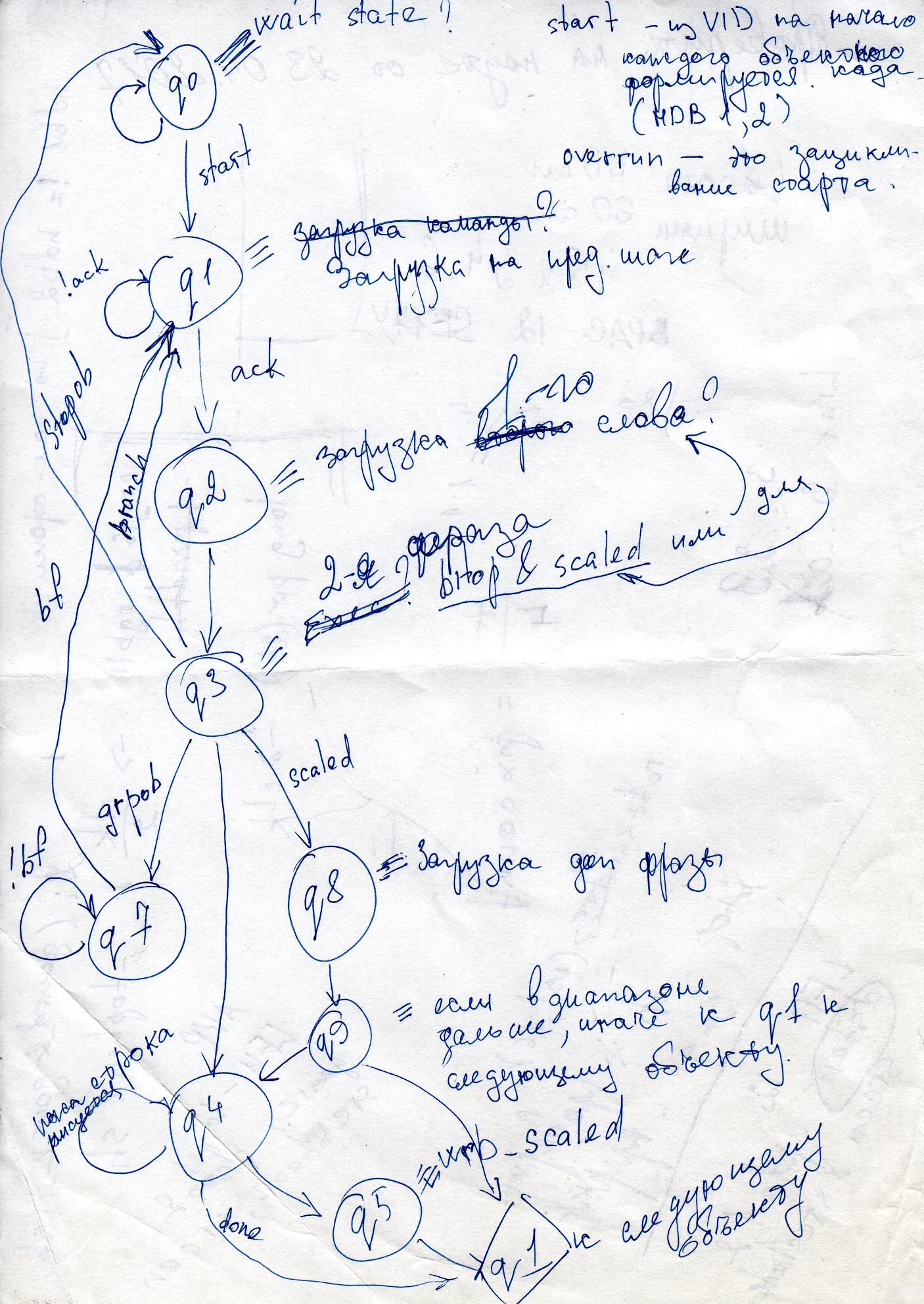
In general, I spent a whole bunch of paper on the sketches of the algorithms to be restored, and a couple of notebooks for notes, plans and lists of hypotheses. As they say - a bad pencil is better than a good memory (including a computer one).
The third stage - hunting for beetles (200 hours)
So, all the blocks are ready and assembled, but according to Murphy’s law, they don’t want to work. As not morally prepared for this, it is still unpleasant to observe a black or artifact freaked-out screen. But, if you are not too lazy to write a convenient debugger, then you will very soon see that the bulk of errors will appear on the very first instructions. If you didn’t write, you can of course be debugged through the development environment debugger and printf, but believe me, writing a debugger is much easier.
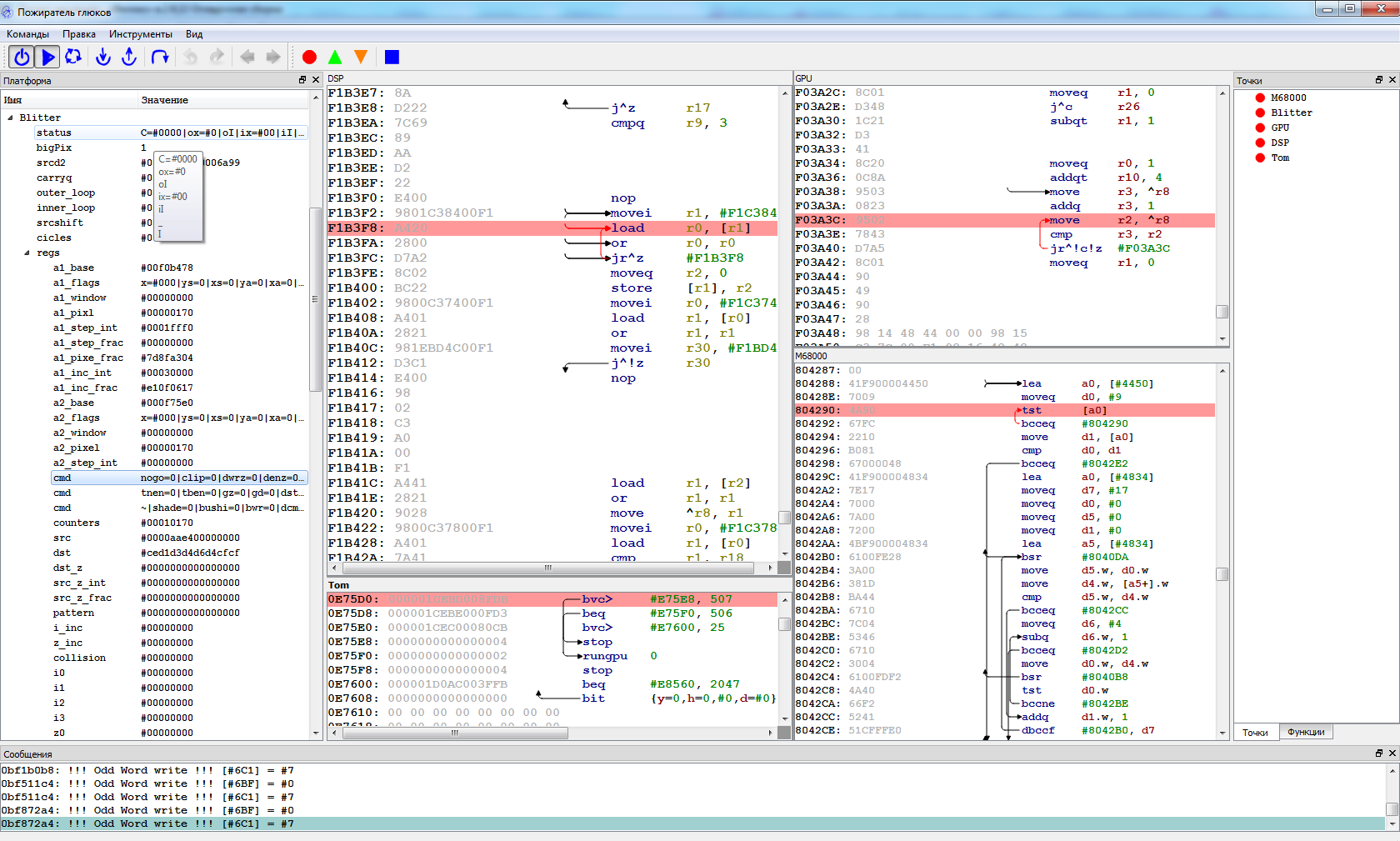
What do I use besides disassemblers and simple console output? For example, the source map, which shows which subsystem made an entry to this memory area, in particular with the 5th Jaguar processors, helped a lot with tracking who was a hooligan (quite often it was a Blitter).
In addition to simple breakpoints for execution, reading or writing in the debugger, it is useful to implement suspend-on-demand functions from the code, for example, I want to check if the GPU or DSP goes beyond the internal memory, and if it does, I cause the stop and transfer of control to the debugger. So I, for example, identified a serious hardware error in the Jaguar. When writing to a flag register with bank switching occurs, then if the next instruction reads the contents of the register, in real hardware it should be from the old bank. This error had to be realized, otherwise the Wolfenshtain and some other games did not work. Yes, in the emulation you need to implement and bugs, and not just features!

Fixed a lot of errors and everything seems to work? No, this is not the end, this is only the beginning of the hunt! Next you need to start testing all available games in all available ways! And here the main thing is not only to find mistakes, but also to make them repeatable, so that it is easy to find the cause. My forum users help me with this, for which I am very grateful, because it is extremely difficult to test even one hundred games by myself - although it is a pleasure to play old games!
As a conclusion
I will talk a little about the basic techniques for improving the performance of emulators, which I use myself.
- Preprocessing . If there is data that is reused (mainly textures), then it makes sense to remember and save them the most processed options for reuse.
- Interlock detection . If it is possible to determine that the processor is waiting for some event - no need to emulate its instructions before the onset of this event.
- Quantization of execution time . From the point of view of the work of the cache, it is better to execute each of several pieces of code many times than to execute them strictly in turn many times. In other words, if it is possible, it is better not to have a tact-based emulation of all devices, but to execute each device as much as possible a portion of cycles.
- Recompilation . Recompilation can be dynamic or static. Static is the fastest, but it is possible only with a small variety of the emulated device code. For example, the DSP code in the 3DO SDK has several hundred tools, so it is quite normal to perform their static recompilation, the code of the central processors, as a rule, is too diverse and here you already need dynamic recompilation.
- Parallel emulation of subsystems . This is not always possible without compromising compatibility, since older multiprocessor systems often used not the most reliable synchronization techniques, and asynchrony in the emulation threads can lead to hangs and other emulation errors, the correction of which can completely offset the gain from multithreading.
What do you need to successfully write an emulator? I think that nothing special is neatness and perseverance, any skills develop with them. There are no special and magical methods.
Source: https://habr.com/ru/post/337566/
All Articles