Multitasking Arduin: pain-free timers
Not every arduinschik knows that in addition to the start code in the setup and an infinite loop in the loop, you can add pieces of code to the robot’s firmware to stop the progress of the main loop at a strictly predetermined time, do their work, then transfer control to the main program so that it does not notice anything at all. Such an opportunity is provided by a timer interrupt mechanism (a common thing for any microcontroller), with its help it is possible to introduce elements of real-time and multitasking into the firmware.
Even less use this opportunity in practice, because it is not provided in the standard not very rich Arduino API. And, although access to all the riches of the microcontroller’s internal capabilities lies at arm's length through connecting one or two system header files, not everyone wants to add a rather specific tuning code to their neat little sketch (incidentally, losing the portability between them). different boards). Only a few (especially among the Arduino audience) will decide and be able to figure it out.
Today I will save you from suffering.
and tell you how to get real multitasking and real time in the firmware of your arduino-robot, adding exactly 3 lines of code to it (including #include in the header). I promise that everything will work out for you, even if you just started Blink for the first time.
')
arduino-timer-api / examples / timer-api / timer-api.ino
We connect the timer-api.h library ( times )
We start the timer with the desired frequency with timer_init_ISR_XYHz : here XYHz = 1Hz - 1 Hertz - one interrupt call per second ( two )
( ISR - interrupt service routine, interrupt handler procedure )
Add to the main loop loop any blocking or non-blocking nonsense: print the message, wait 5 seconds ( everything is as usual here, so we don’t count )
The procedure caused by a timer interrupt with a specified period is the implementation for the function named timer_handle_interrupts : we print a message, we blink a light bulb ( three )
The same thing, just add time metering between the two calls for clarity and debugging:
We sew the board, open Tools> Port Monitor , see the result:
As you can see, the timer_handle_interrupts handler prints a message every 1,000,000 (1 million) microseconds, i.e. exactly once a second. And (lo and behold!) The constant blocking delay for 5 seconds delay (5000) in the main loop in no way interferes with this action.
Here you have real time and multitasking in one sketch in 3 lines, I promised.
( there is also a call to timer_init_ISR_1MHz, but it does not give a working result on any of the test controllers )
The interrupt code must obviously be executed fast enough to complete before the next interrupt call and, preferably, still leave some processor time to execute the main loop.
I suppose it is unnecessary to clarify that the higher the timer frequency, the shorter the interrupt call period, the faster the handler code must be executed. I would not recommend placing in it calls of blocking delay delays, cycles with a number of advance unknowns, any other calls with poorly predictable execution times (including Serial.print ).
In the event that the standard frequencies offered by the choice do not suit you, you can enter an additional counter in the interrupt code, which will execute the useful code only after a certain number of missed calls. The target period will be equal to the sum of the skipped base periods. Or you can make it generally variable.
arduino-timer-api / examples / timer-api-counter / timer-api-counter.ino
There is another option to set an arbitrary (within certain limits) timer frequency value by calling timer_init_ISR (timer, prescaler, adjustment) with parameters — the system clock divider of the prescaler processor frequency and an arbitrary adjustment value to be placed in the timer counter register.
Without going into details, in order not to overload the post, I will provide a link to an example with detailed comments:
arduino-timer-api / examples / timer-api-custom-clock / timer-api-custom-clock.ino
And just note that using this approach can lead to loss of code portability between controllers with different clock frequencies, since The parameters for obtaining the target frequency of the timer are selected in direct proportion to the frequency of the system signal generator on the chip, the digit capacity of the timer, the available options for the prescaler system dividers.
To stop the timer, use the timer_stop_ISR call, to restart, use any option timer_init_ISR_XYHz , as before.
arduino-timer-api / examples / timer-api-start-stop / timer-api-start-stop.ino
Clone repository directly to the library directory
and restart the Arduino environment.
Or on the arduino-timer-api project page download Clone or download> Download ZIP snapshot repository or one of the releases as an archive, then install the arduino-timer-api-master.zip archive via the library installation menu in the Arduino environment ( Sketch> Connect library > Add a .zip library ... ).
Examples should appear in the menu File> Examples> arduino-timer-api
- Atmega / AVR 16 bit 16 MHz for Arduino
- SAM / ARM 32 bit 84 MHz for Arduino Due
- PIC32MX / MIPS 32 bit 80 MHz on the ChipKIT family (PIC32MZ / MIPS 200 MHz - partially, in operation)
Stepping motor rotation via step-dir interface:
- in the background on the timer, we generate a constant rectangular signal for the step along the front HIGH-> LOW on the STEP leg
- in the main loop, we accept commands from the user to select the direction of rotation (DIR leg) or stop the motor (EN leg) via the serial port
arduino-timer-api / examples / timer-api-stepper / timer-api-stepper.ino
Even less use this opportunity in practice, because it is not provided in the standard not very rich Arduino API. And, although access to all the riches of the microcontroller’s internal capabilities lies at arm's length through connecting one or two system header files, not everyone wants to add a rather specific tuning code to their neat little sketch (incidentally, losing the portability between them). different boards). Only a few (especially among the Arduino audience) will decide and be able to figure it out.
Today I will save you from suffering.
and tell you how to get real multitasking and real time in the firmware of your arduino-robot, adding exactly 3 lines of code to it (including #include in the header). I promise that everything will work out for you, even if you just started Blink for the first time.
')
Let's start right away with the code
arduino-timer-api / examples / timer-api / timer-api.ino
We connect the timer-api.h library ( times )
#include "timer-api.h" We start the timer with the desired frequency with timer_init_ISR_XYHz : here XYHz = 1Hz - 1 Hertz - one interrupt call per second ( two )
void setup() { Serial.begin(9600); // =1, =1 timer_init_ISR_1Hz(TIMER_DEFAULT); pinMode(13, OUTPUT); } ( ISR - interrupt service routine, interrupt handler procedure )
Add to the main loop loop any blocking or non-blocking nonsense: print the message, wait 5 seconds ( everything is as usual here, so we don’t count )
void loop() { Serial.println("Hello from loop!"); delay(5000); // : } The procedure caused by a timer interrupt with a specified period is the implementation for the function named timer_handle_interrupts : we print a message, we blink a light bulb ( three )
void timer_handle_interrupts(int timer) { Serial.println("goodbye from timer"); // digitalWrite(13, !digitalRead(13)); } The same thing, just add time metering between the two calls for clarity and debugging:
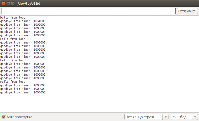
void timer_handle_interrupts(int timer) { static unsigned long prev_time = 0; unsigned long _time = micros(); unsigned long _period = _time - prev_time; prev_time = _time; Serial.print("goodbye from timer: "); Serial.println(_period, DEC); // digitalWrite(13, !digitalRead(13)); } We sew the board, open Tools> Port Monitor , see the result:
As you can see, the timer_handle_interrupts handler prints a message every 1,000,000 (1 million) microseconds, i.e. exactly once a second. And (lo and behold!) The constant blocking delay for 5 seconds delay (5000) in the main loop in no way interferes with this action.
Here you have real time and multitasking in one sketch in 3 lines, I promised.
Frequency options for timer_init_ISR_XYHz
//timer_init_ISR_500KHz(TIMER_DEFAULT); //timer_init_ISR_200KHz(TIMER_DEFAULT); //timer_init_ISR_100KHz(TIMER_DEFAULT); //timer_init_ISR_50KHz(TIMER_DEFAULT); //timer_init_ISR_20KHz(TIMER_DEFAULT); //timer_init_ISR_10KHz(TIMER_DEFAULT); //timer_init_ISR_5KHz(TIMER_DEFAULT); //timer_init_ISR_2KHz(TIMER_DEFAULT); //timer_init_ISR_1KHz(TIMER_DEFAULT); //timer_init_ISR_500Hz(TIMER_DEFAULT); //timer_init_ISR_200Hz(TIMER_DEFAULT); //timer_init_ISR_100Hz(TIMER_DEFAULT); //timer_init_ISR_50Hz(TIMER_DEFAULT); //timer_init_ISR_20Hz(TIMER_DEFAULT); //timer_init_ISR_10Hz(TIMER_DEFAULT); //timer_init_ISR_5Hz(TIMER_DEFAULT); //timer_init_ISR_2Hz(TIMER_DEFAULT); //timer_init_ISR_1Hz(TIMER_DEFAULT); ( there is also a call to timer_init_ISR_1MHz, but it does not give a working result on any of the test controllers )
The interrupt code must obviously be executed fast enough to complete before the next interrupt call and, preferably, still leave some processor time to execute the main loop.
I suppose it is unnecessary to clarify that the higher the timer frequency, the shorter the interrupt call period, the faster the handler code must be executed. I would not recommend placing in it calls of blocking delay delays, cycles with a number of advance unknowns, any other calls with poorly predictable execution times (including Serial.print ).
Summation of periods (frequency division)
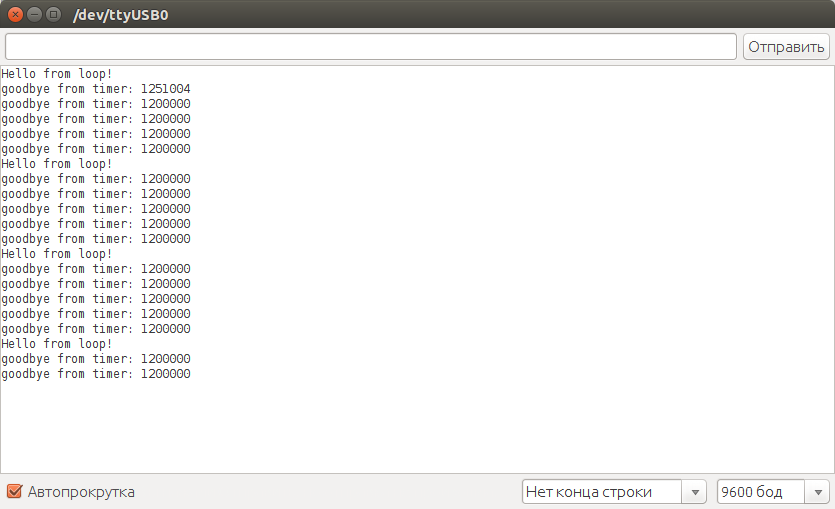
In the event that the standard frequencies offered by the choice do not suit you, you can enter an additional counter in the interrupt code, which will execute the useful code only after a certain number of missed calls. The target period will be equal to the sum of the skipped base periods. Or you can make it generally variable.
arduino-timer-api / examples / timer-api-counter / timer-api-counter.ino
#include"timer-api.h" void setup() { Serial.begin(9600); while(!Serial); // =10, =100 timer_init_ISR_10Hz(TIMER_DEFAULT); pinMode(13, OUTPUT); } void loop() { Serial.println("Hello from loop!"); delay(6000); // : } void timer_handle_interrupts(int timer) { static unsigned long prev_time = 0; // static int count = 11; // 12 : // 10 100, // 100*12=1200 // (5 6 ) if(count == 0) { unsigned long _time = micros(); unsigned long _period = _time - prev_time; prev_time = _time; Serial.print("goodbye from timer: "); Serial.println(_period, DEC); // digitalWrite(13, !digitalRead(13)); // count = 11; } else { count--; } } Arbitrary frequency
There is another option to set an arbitrary (within certain limits) timer frequency value by calling timer_init_ISR (timer, prescaler, adjustment) with parameters — the system clock divider of the prescaler processor frequency and an arbitrary adjustment value to be placed in the timer counter register.
Without going into details, in order not to overload the post, I will provide a link to an example with detailed comments:
arduino-timer-api / examples / timer-api-custom-clock / timer-api-custom-clock.ino
And just note that using this approach can lead to loss of code portability between controllers with different clock frequencies, since The parameters for obtaining the target frequency of the timer are selected in direct proportion to the frequency of the system signal generator on the chip, the digit capacity of the timer, the available options for the prescaler system dividers.
Starting and stopping the timer in the dynamics
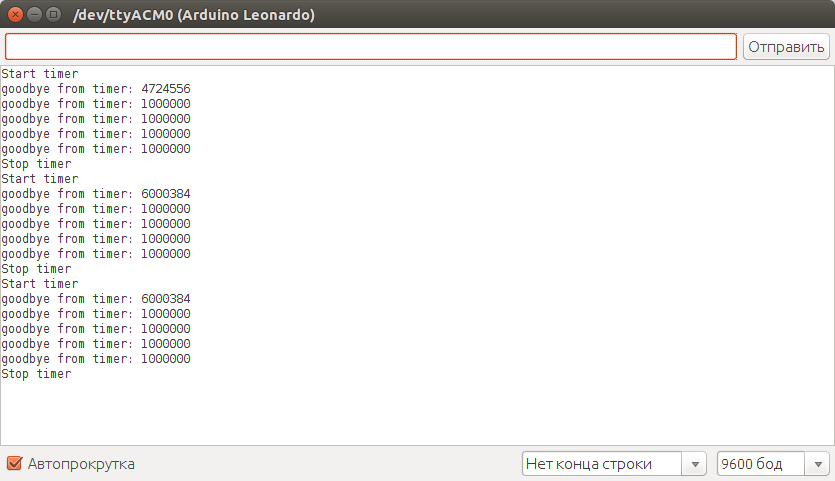
To stop the timer, use the timer_stop_ISR call, to restart, use any option timer_init_ISR_XYHz , as before.
arduino-timer-api / examples / timer-api-start-stop / timer-api-start-stop.ino
#include"timer-api.h" int _timer = TIMER_DEFAULT; void setup() { Serial.begin(9600); while(!Serial); pinMode(13, OUTPUT); } void loop() { Serial.println("Start timer"); timer_init_ISR_1Hz(_timer); delay(5000); Serial.println("Stop timer"); timer_stop_ISR(_timer); delay(5000); } void timer_handle_interrupts(int timer) { static unsigned long prev_time = 0; unsigned long _time = micros(); unsigned long _period = _time - prev_time; prev_time = _time; Serial.print("goodbye from timer: "); Serial.println(_period, DEC); // digitalWrite(13, !digitalRead(13)); } Library installation
Clone repository directly to the library directory
cd ~/Arduino/libraries/ git clone https://github.com/sadr0b0t/arduino-timer-api.git and restart the Arduino environment.
Or on the arduino-timer-api project page download Clone or download> Download ZIP snapshot repository or one of the releases as an archive, then install the arduino-timer-api-master.zip archive via the library installation menu in the Arduino environment ( Sketch> Connect library > Add a .zip library ... ).
Examples should appear in the menu File> Examples> arduino-timer-api
Supported chips and platforms
- Atmega / AVR 16 bit 16 MHz for Arduino
- SAM / ARM 32 bit 84 MHz for Arduino Due
- PIC32MX / MIPS 32 bit 80 MHz on the ChipKIT family (PIC32MZ / MIPS 200 MHz - partially, in operation)
And finally,
Stepping motor rotation via step-dir interface:
- in the background on the timer, we generate a constant rectangular signal for the step along the front HIGH-> LOW on the STEP leg
- in the main loop, we accept commands from the user to select the direction of rotation (DIR leg) or stop the motor (EN leg) via the serial port
arduino-timer-api / examples / timer-api-stepper / timer-api-stepper.ino
#include"timer-api.h" // // Pinout for CNC-shield // http://blog.protoneer.co.nz/arduino-cnc-shield/ // X #define STEP_PIN 2 #define DIR_PIN 5 #define EN_PIN 8 // Y //#define STEP_PIN 3 //#define DIR_PIN 6 //#define EN_PIN 8 // Z //#define STEP_PIN 4 //#define DIR_PIN 7 //#define EN_PIN 8 void setup() { Serial.begin(9600); // step-dir motor driver pins // step-dir pinMode(STEP_PIN, OUTPUT); pinMode(DIR_PIN, OUTPUT); pinMode(EN_PIN, OUTPUT); // , // // . // // : // https://github.com/sadr0b0t/stepper_h // 1/1: 1500 // 1/2: 650 // 1/4: 330 // 1/8: 180 // 1/16: 80 // 1/32: 40 // 1/1 // =500, =2 //timer_init_ISR_500Hz(TIMER_DEFAULT); // timer_init_ISR_200Hz(TIMER_DEFAULT); // 1/2 // =1, =1 //timer_init_ISR_1KHz(TIMER_DEFAULT); // //timer_init_ISR_500Hz(TIMER_DEFAULT); // 1/4 // =2, =500 //timer_init_ISR_2KHz(TIMER_DEFAULT); // //timer_init_ISR_1KHz(TIMER_DEFAULT); // 1/8 // =5, =200 //timer_init_ISR_5KHz(TIMER_DEFAULT); // //timer_init_ISR_2KHz(TIMER_DEFAULT); // 1/16 // =10, =100 //timer_init_ISR_10KHz(TIMER_DEFAULT); // //timer_init_ISR_5KHz(TIMER_DEFAULT); // 1/32 // =20, =50 //timer_init_ISR_20KHz(TIMER_DEFAULT); // //timer_init_ISR_10KHz(TIMER_DEFAULT); ///////// // // EN=HIGH to disable digitalWrite(EN_PIN, HIGH); // Serial.println("Choose direction: '<' '>', space or 's' to stop"); } void loop() { if(Serial.available() > 0) { // : int inByte = Serial.read(); if(inByte == '<' || inByte == ',') { Serial.println("go back"); // digitalWrite(DIR_PIN, HIGH); // EN=LOW to enable digitalWrite(EN_PIN, LOW); } else if(inByte == '>' || inByte == '.') { Serial.println("go forth"); // digitalWrite(DIR_PIN, LOW); // EN=LOW to enable digitalWrite(EN_PIN, LOW); } else if(inByte == ' ' || inByte == 's') { Serial.println("stop"); // // EN=HIGH to disable digitalWrite(EN_PIN, HIGH); } else { Serial.println("press '<' or '>' to choose direction, space or 's' to stop,"); } } delay(100); } void timer_handle_interrupts(int timer) { // HIGH->LOW digitalWrite(STEP_PIN, HIGH); delayMicroseconds(1); digitalWrite(STEP_PIN, LOW); } Source: https://habr.com/ru/post/337430/
All Articles