The practice of forming requirements in IT projects from A to Z. Part 5. Essence of the subject area and a little about strategies
All parts
Part 1. Introduction
Part 2. Goals and Needs
Part 3. System Functions and Project Boundaries
Part 4. Business processes automated by the system.
Part 5. Essence of the subject area and a little about strategies
Part 6. Behavior of the system. Excellence requirements
Part 7. The transfer of requirements in production. Conclusion
VIII Determine the essence of the subject area
All that we see is only one visibility.
Far from the surface of the world to the bottom.
Consider the insignificant obvious in the world
For the secret essence of things is not visible
Omar Khayyam

Having determined the abstract storage of the product, we get the backbone for building a detailed data model. When designing the structure of product entities, it is convenient to use canonical “Essence-relationship” diagrams (ERD), logic diagram (Logic Diagram) or class diagram (Class diagram).
The purpose of this group of works is to design a data warehousing model for use in a product, as well as to document system entities and how they interact.
The theory of designing this type of diagrams is detailed in the literature describing working with UML. For example, this topic is very well represented in [11]. Therefore, I’ll dwell only on some aspects that are interesting in my opinion.
Figure 8.1 shows the process of formalizing the requirements for the target system, supplemented by a subprocess for determining the entities of the subject area.
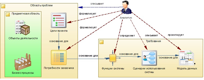
Figure 8.1 - the process model for determining the entities of the subject area
')
For a better understanding of the nature of Entities modeled in the system, you can divide them into the following types (resources):
- Matter \ Substance - all material, "physical", having a mass, length, localization in space, showing corpuscular properties;
- Energy - a single measure of various forms of motion and interaction of matter, a reflection of the variability of matter, transitions from one type to another;
- Information - information perceived by a person or special devices as a reflection of the facts of the material world in the process of communication;
- The person is the carrier of the intellect of the highest level. In the economic, social, humanitarian sense, it is the most important and unique resource of society, it acts as a measure of reason, intelligence and purposeful action, a measure of social principle, the highest form of reflection of matter (consciousness);
- Organization - a form of resources in society, the group that defines its structure, including the institutions of human society and its superstructure, acts as a measure of the orderliness of resources. The organization of the system can take various forms, for example, biological, informational, ecological, economic, social, temporal, spatial;
- Space is a measure of the extent of matter (event), its distribution in the environment;
- Time is a measure of the reversibility (irreversibility) of matter, events. Time is inextricably linked with changes in reality;
Most of the resources are closely related to each other in nature and can not exist without each other. Therefore, when identifying a single resource (entity), in the subject domain under consideration, using the above typing, it is possible to determine the resources (entities) associated with it - satellites. And if they are essential from the point of view of the model being developed, they will take care of including them in this model. Moreover, certain templates can be developed for describing entities of different types, allowing not to miss their important properties, states in the life cycle, etc., and adhere to a single standard.
When making a decision about inclusion / exclusion of an entity in a model, it is necessary to be guided by one of the basic principles of “System Analysis” - consider the totality of the system elements as a single whole or, arguing from the opposite, the prohibition of considering the system as a simple combination of its elements.
Another important principle that should not be forgotten is the need to consider the system only in union with its environment. This means that any system should be considered a part of a more general, global system.
1. We use encapsulation
The term “Encapsulation” has several interpretations and interpretations. I like the following option: Encapsulation - ensuring the availability of the main one, highlighting the main content by placing the entire disturbing, secondary in a kind of conventional capsule (black box). From the point of view of system analysis, it is an element of the abstraction process.
Encapsulation, as is known, reduces the “fragility” of the system as a whole, due to the fact that it hides the implementation in the object, localizing the distribution of errors throughout the product. This topic is very well described in the book [8]. Systems built on this principle are easy to upgrade, replacing solid structures without serious consequences. It is also very effective when developing individual product modules with different teams.
Therefore, when developing the structure of the system, try to divide it into self-sufficient modules, services, etc., which are responsible for a certain specialization. It is desirable that these constructs communicate with each other through well-defined interfaces.
An example of crushing a module (part of a system) into self-sufficient segments is shown in Figure 8.2. For a visual perception of the elements of the system and their interaction, it is convenient to use models built on the basis of the diagram “Application Architectures”.
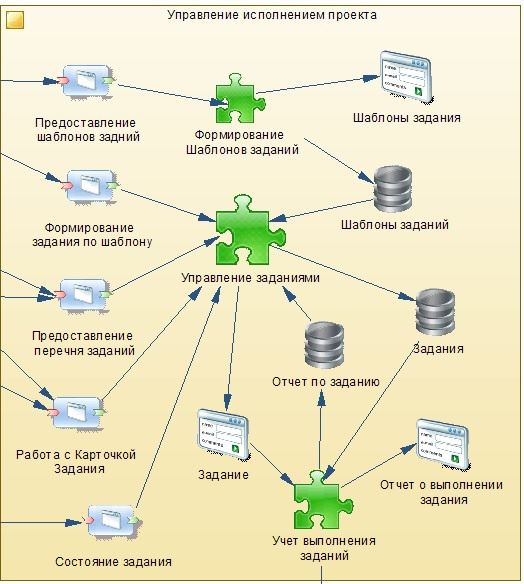
Fig. 8.2 - Fragment diagram of the architecture of the project execution control module
As can be seen from the figure, the project execution management module is divided into three segments (in the diagram they are depicted with green “puzzles”):
- Creation of job templates;
- Job management;
- Accounting tasks;
Please note that the module has interface methods (shown on the left) that separate the implementation of this module from the rest of the system and allow it to “communicate” with its other (system) elements.
Since we have identified three segments in the module under consideration, it is also convenient to design the data structure on three separate diagrams. Elements designed for some segments can be used on diagrams of other segments (they will be highlighted with the signature of their segment). In large projects, this is a very important point, allowing you not to “choke” in the sea of designed objects.
Figure 8.3 shows an example of a class diagram of a segment called “Management of interested parties”. Pay attention to the classes: “Task Map” and “Task Card Status” belonging to another “Task Management” segment from the “Project Performance Management” module, which we discussed above. In this case, elements designed in other diagrams usually have a link (signature) to the parent diagram, it is indicated in parentheses under the name of the element (class).
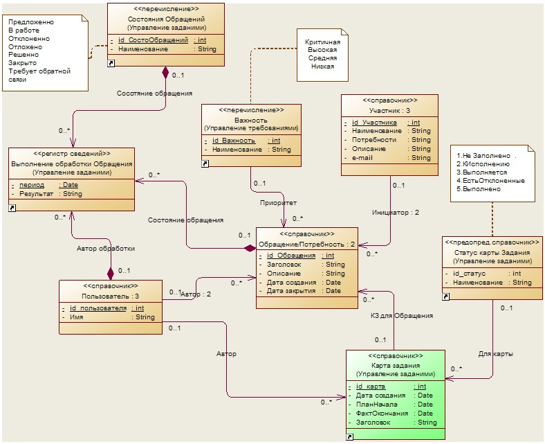
Fig. 8.3 - Class diagram of the segment Management of applications of interested persons
If you go ahead and look below at Figure 8.5, then there is an example of a class diagram for another segment described above - “Formation of Task Templates”.
But it should be remembered that too complex encapsulation leads to a decrease in manageability and narrows the applicability of the module. This will be described in more detail in the next chapter.
Thus, the “Application Architectures” diagrams are conveniently used by the command as a starting (upper) point of abstraction presenting a system, each element of which is a composition, represented, for example, in the form of a class diagram.
2. Effectively use business entity decomposition
Decomposition, from the point of view of system analysis, is the method by which the system under investigation is divided into subsystems, the task of subtasks, etc., each of which is solved independently.
Decomposition, as a process of dismemberment, allows us to consider any system under investigation as complex, consisting of separate interconnected subsystems, which, in turn, can also be dismembered into parts. Not only material objects can act as systems, but also processes, phenomena and concepts.
When designing an entity, try to decompose in such a way that if some of its attributes change during different events, the entity will be divided into parts corresponding to these events. For example, the Entity Requirement may have attributes:
- Identifier;
- Date of creation;
- Title;
- Description;
- Condition;
In this example, the Identifier and Creation Date attributes will change only at the time the record is created. Attributes Description and Title may change as requirements are refined, or when customer needs change. And the Status attribute changes when assignments are made on demand and are executed. In this case, it would be nice to have also a history of all changes. Thus, the “Requirement” entity can be divided into three relational tables: 1) Requirement specification, 2) Requirement content, 3) Requirement status, see Figure 8.4

Fig. 8.4 - Requirements Classes Chart
But do not forget, using this technique, to support the ninth rule of Codd:
Rule 9: Logical Data Independence:
The presentation of data in an application should not depend on the structure of relational tables. If during the normalization process one relational table is divided into two, the view should ensure that this data is combined so that the change in the structure of relational tables does not affect the operation of the applications.
In my practice, there was a case when the team used a table with the number of fields - more than 500. Different events changed only part of the attributes, and the entire data tuple was recorded. It is also very wasteful to keep the history of such tables. When changing one field in the source table, a new line is written in the history table with the values of all attributes.
But there is a downside. If you perform the decomposition very finely, breaking complex entities into many simple ones with a limited number of attributes, then in the end, in a large project, you may end up with a structure that is hard to grasp with understanding and therefore hard to maintain.
In my opinion, the complexity of the structure should be proportional to the qualifications of the developers and analysts involved in the project, as well as the capabilities of the tools used by the team. But when accepting a position of using a complex structure, even if there is a strong team, there is a risk - sooner or later, to lose her (the team) or her members and then the maintenance and development of the product can become difficult.
3. We use adaptive data models
Another possibility to reduce the complexity caused by the use of a large number of entities is the use of data processing universalization mechanisms. For example, the use of templates, model entities, on the basis of which instances are created. Such models are called adaptive. The concept of management with adaptation implies management in a system with incomplete a priori information about the controlled process, which changes as information accumulates and is used to improve the quality of the system.
But here the same dilemma arises: the mechanism of universalization should not exceed the complexity of the data structure, which could be used without the appropriate mechanism.
At the time of system design, it is necessary to determine the prospects for the development of product functionality. If you see that some kind of universal processing mechanism at the first stage will be used only partially, but it has prospects for further loading, then such a mechanism should be designed and built immediately. This will not only significantly compensate for and save time with the further development of the product, but also reduce the number of supported entities.
To reduce the inevitable costs in the design and implementation of adaptive systems, it is necessary to consider the following aspects of the choice of solutions:
- Optimum selection of criteria with a fixed algorithm;
- Selection of the best adaptation algorithm with fixed criteria;
- Variation of algorithms and criteria;
Let us briefly analyze an example of using the task setting mechanism according to the template, see Figure 8.5. On the diagram, blue color indicates entities modeling Patterns or Typical entities, and green entities that simulate objects formed on the basis of these patterns.

Fig. 8.5 - Classes Diagram for Shaping Template Tasks
For a unified perception of the terms of the subject area, we update our Glossary:

Thus, the typical entity “Template of the task map” (hereinafter, we use the notation SHKZ) is intended to form, on the basis of its structure, instances of the “Task map” entity. That is, by creating a certain set of Task Card Templates, we will be able to use them in the future to quickly fill in new Task Maps for performing work in a project.
Now in more detail about the structure of SHKZ. SHKZ includes, as an aggregate, the typical entity “Template back” and links its instances into one business scenario. In the SHKZ, the Position (position) is indicated to determine the person responsible for the process. This property, when a new Task Map is being created on the basis of the SKKZ, will automatically determine the user currently appointed to the position in the organization and applying for the role of task group supervisor.
The following typical entity, mentioned just above, the “Task Template”, designed to form new Tasks on it, is characterized by the following attributes: the order of the tasks in the SCR, the position of the task performer, the type of activity and (as a bonus) a list of parameters that can be customized. The parameters for the task template are used as an additional mechanism that expands the variability of its application and can be assigned both inbound and outbound. Parameters, as a rule, are associated with other entities of the system and, when setting tasks, are substituted for the current states (argument values) of these entities. Next we will return to the topic of parameters and talk about them in more detail.
Let us now consider the reason for which we started all this typing - entities, instances of which are formed on the basis of Typical entities. For example, the "Task Map" is formed on the basis of the SHKZ and is designed to group tasks assigned to performers as related step-by-step operations. The next such Entity is “Tasks”, which are formed by a typical entity - “Task Template”. For the Task Map, the person in charge can be automatically determined (this was mentioned above in the description of the SHKZ). According to the standard position, when assigning a Task, the performer assigned to perform it is automatically determined, including the “agent-robot” of the system. By the type of task, for a robot or a person, the procedure to be performed can be identified.
Thus, having set up the Standard Tasks in the target product, we get the system of automatic generation of Task Maps for performers. Now, when the need arises to set up a new business process, either minimal intervention from the developers is required, or it will not be required at all. And since the system we are developing must have the ability to form different types of tasks (development, testing, implementation, etc.), including their different sequences within one process, the creation of such a mechanism should pay off with interest.
You can obviously argue that now there are serious libraries that support BPMN models and their implementation without coding. But we are considering an educational project with you, make a condescension.
4. Using design patterns
Use refactoring of modeling processes, referring to design patterns, including creating your own templates. This topic is well disclosed in [12]. The reuse of certain design patterns will not only save time in the product development process, but also facilitate its support and upgrades.
It is very important that the analyst, having met the need to overcome a certain problem, similar to the one that has already been solved, tried to universalize this solution using a template. Such templates should be developed and approved together with the project team. Then the whole group of both developers and designers will “unwittingly” follow the need for their use and the correct application.
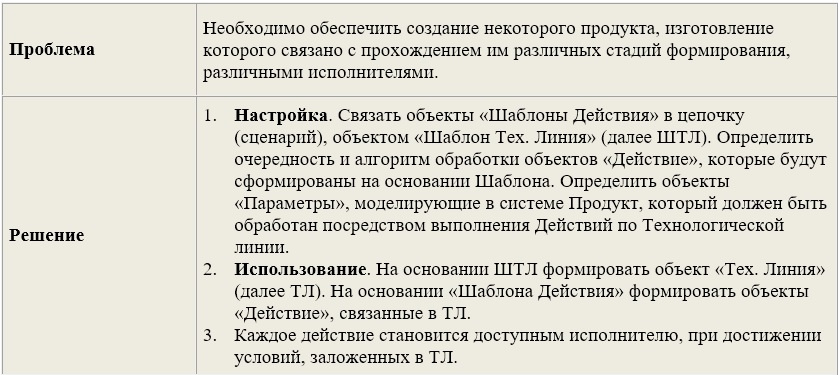
For example, on the basis of the structure discussed in the previous section, we can develop a template "Technological line", which may be useful to us, to create a mechanism for the step-by-step formation of design documents. The technological line will actually play the role of a conveyor delivering the “Product” formed by it (in our case, a design document) to the places of its processing, according to a specific event.
I will give his description:
Technological line (Production Line)
An example of the implementation of the data structure for the Technological Line pattern is shown in Figure 8.6.
As can be seen from the diagram, the data structure almost completely repeats the diagram “Formation Back by templates”, see Figure 8.4. The description of the mechanisms determining the work of the template is mostly similar to the process of “Creating Tasks from Templates” presented in the previous section. Let us dwell in more detail only on those moments that were not covered above, in particular, the mechanism for determining and forming the Action Parameters.
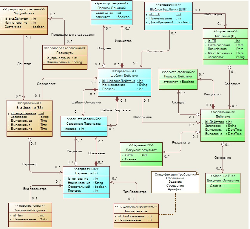
Fig. 8.6 - Classes Diagram of the Process Line Pattern
For each Action Template, a list of parameters is determined, based on the “Task Type” assigned to the template. The parameter can be either the “Basis” for the task, or the “Result” of its execution. Each parameter has a type that defines the essence of the “Product” (in our case, the design document) processed by the Processing Line. Based on the parameters defined for the template, during the formation of the action, a specific entity instance will be identified, and a reference to it will be recorded as the “Foundations” parameter for the action. After performing an action, if the Result parameter is defined for it (the action forms or changes the document), a link to its specific instance will be stored in this parameter.
It is important that the outgoing parameter of one action can be assigned as an input parameter for the next action in the process line. Thus, the formed “Product” passes through the nodes of the process line.
5. Do not forget about the development strategy of the product line
In practice, it is often necessary not only to develop a new software product, but to perform the replacement of outdated software, and in the worst case, inherited from another development team. In this case, the nature of the work changes and the complexity of the project as a whole increases. This is due to a number of reasons that we consider in this section. When designing such systems, the following factors should be considered:
- availability of technologies already used product, experience of its implementation and problems of operation;
- established habits and traditions of users interacting with the software being replaced for a long time;
- the need to transfer data from the old system to the new one, and perhaps the synchronization of the work of both systems for some time.
Carrying out the project associated with the changes, it is very important to manage the process of change, and not to “rake out” problems that arise during its implementation. Therefore, before starting the design, it is desirable to conduct the audit of the systems used as fully as possible and develop a strategy for the transition from the old to the new based on it.
In order to qualitatively develop a transition strategy, it is necessary to take into account the nature of the emergence of such a need in each specific case. The main reasons for the change in automation tools include:
- Changes in external, in relation to the system, conditions affecting its functioning. For example, changes in legislation;
- The fight against disorganization in the system, associated with the rapid accumulation of information and changes in the requirements for its quality;
- Fight against “fatigue”, “fragility” and “redundancy” of software caused by frequent changes that conflict with its original design;
- Qualitative change of system infrastructure. For example, tightening security requirements;
Therefore, in projects related to changes, it is necessary to take into account not only technological aspects, but also human, organizational and even political factors.
One of the critical conditions for introducing changes is the active and, not least, emotional involvement of all stakeholders in the processes of discussion and the development of a strategy for transition from the old to the new.
To begin with, it is necessary to realize that the executors of the process being modernized already have a real operating tool to maintain its functioning, and the creation and implementation of any new technology is a threat of the destruction of this tool. And for the customer’s employees it’s not at all obvious that as a result of the modernization, there will be an adequate replacement of the existing solution. Therefore, often, the negative attitude of future users to the new system is only a defensive reaction. We must make them trust you.
Employees who should be affected by the change from the earliest stages of the project should in no way be in the dark about how their production process should be organized after the innovations. On the contrary, they should be involved in the design of a new product. Let them feel that they are the authors of the new system, that they are responsible for how it will turn out.
To attract as many people as possible to the change process, it is necessary to give them the opportunity to visually and emotionally attractively present the context of these changes. Namely: a list of changeable processes, compliance of old processes with new ones, steps and conditions of transition, etc. Use to visualize the model of the transition strategy from the old system to the target, already mentioned above, the diagram "Application Architectures". An example of the presentation of the strategy for the project we are considering is shown in Figure 8.7.
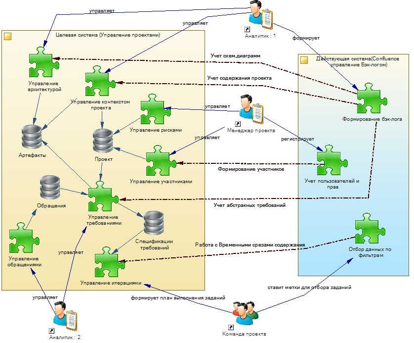
Fig. 8.7 - Diagram of the presentation of the strategy of transition from the used architecture to the target
The diagram shows two system views: Active, which is currently working (it is highlighted in blue) and Target, which should replace it (it is highlighted in yellow). The dashed arrows mark the comparison of the modules and functions of the Target System with those that they must replace in the Active.
As a result of the discussion of this scheme (and other documents) there should appear a list of stages and activities that will allow moving from the Current System to the Target.
Such diagrams help, for example, to identify relatively self-sufficient services that could function for some time in the old system and allow the new (target) system to interact with them. This can be very useful when planning in a project a step-by-step introduction of a new product.
Since the process of replacing old software with a new one is long-lasting and is associated with the manifestation of many difficult to predict risks, it is necessary to constantly monitor the progress of the transition. With the constant postponement of timely making the necessary changes to the software, the problem of its stagnation is sharply exacerbated. Since the dependence of resources allocated for software modification on their volume is non-linear, the cost of modifying stagnant software also increases non-linearly. When the cost of modification increases so much that the customer becomes unable to further change the software, it becomes conditionally “unchanged”. This is very clearly stated in [8].
To combat such problems, you can determine in advance the milestones of the project and accurately track their occurrence (or non-occurrence). Delaying the process of change is likely to lead to a breakdown of the entire project. Indeed, the introduction of each stage is often also associated with stress for users and an additional load on them. If the execution of any of the stages was not crowned with success, then it may be necessary to “roll back” to the previous stage. Two or three of these "rollbacks" and the customer can refuse to continue the transition to new software, since the cost of changes becomes critical.
All of the above makes us take a particularly serious approach to the issues of a clear and quick response to problems that prove to be obstacles that stop or significantly slow down the process of making changes.
It is important, when performing actions on strategic changes, to constantly monitor barriers that impede the actual achievement of the planned goals. For this, all such facts are recorded, brought to the attention of interested persons and together with them a plan of measures is developed for their elimination.
According to John Kotter’s change management approach: “Change takes place by achieving short-term successes that happen again and again, accumulating aggregate energy opposing skeptics and cynics. That is why success is necessary to demonstrate in every way the staff and all stakeholders of the project. That is what will help achieve respect and trust in innovation. "
In the next part, we will define the behavior of the system link .
Bibliography
1. Jacobson A., Butch G., Rambo J. - “Unified Software Development Process” (2004)
2. David A. Mark and Clement McGowan - “SADT Structural Analysis and Design Methodology”
3. Coburn - "Modern methods for describing functional requirements" (2002)
4. Leffingwell Dean, Widrich Don - “Principles of working with software requirements” (2002)
5. Karl I. Wigers - “Developing Software Requirements” (2002)
6. Elizabeth Hull, Ken Jackson, Jeremy Dick - “Developing and Managing Requirements A Practical User Guide” (2005)
7. Scott Ambler - “Flexible Technologies: Extreme Programming and a Unified Development Process” (2005)
8. Greenfield Jack, Kane Short - "Software Development Factories" (2007)
9. Alistair Cowburn - “Each project has its own methodology”
10. Wolfson Boris - “Flexible development methodologies”
11. Leszek A. - “Requirements Analysis and System Design”
12. Freeman Eric, Freeman Elizabeth - “Design Patterns” (2011)
13. Evans Erik - “Subject-Oriented Design” (2011)
14. GOST 34.602-89 “Information technology. Set of standards for automated systems. Terms of Reference for the creation of an automated system "
Source: https://habr.com/ru/post/337400/
All Articles