Traffic mirroring on Juniper MX

Today we will talk about traffic mirroring on Juniper MX series routers. After Cisco, Huawei or Arista switches, the configuration of SPAN and RSPAN on JunOS will seem very complicated, but the complex (at first glance) configuration hides the enormous capabilities of the MX platform in the area of traffic mirroring. Although Juniper’s approach is complex at first glance, it becomes simple and straightforward if you don’t stupidly copy-paste configs from one box to another, but understand what is being done and why. JunOS ideology suggests using filter based forwarding (FBF) for mirroring purposes, which gives us some flexibility in implementing complex traffic mirroring schemes.
So, let's begin. We will look at a few examples of mirroring:
1. Local mirroring from port to port
2. Mirroring into two or more consumers
3. Mirroring to a remote host
4. Selective mirroring for two or more consumers
5. Local mirroring of L2 traffic
6. Mirroring L2 traffic to a remote server
7. Using more than two mirroring instances on one FPC
')
So let's start in order.
Local mirroring from port to port.
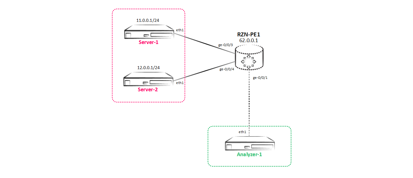
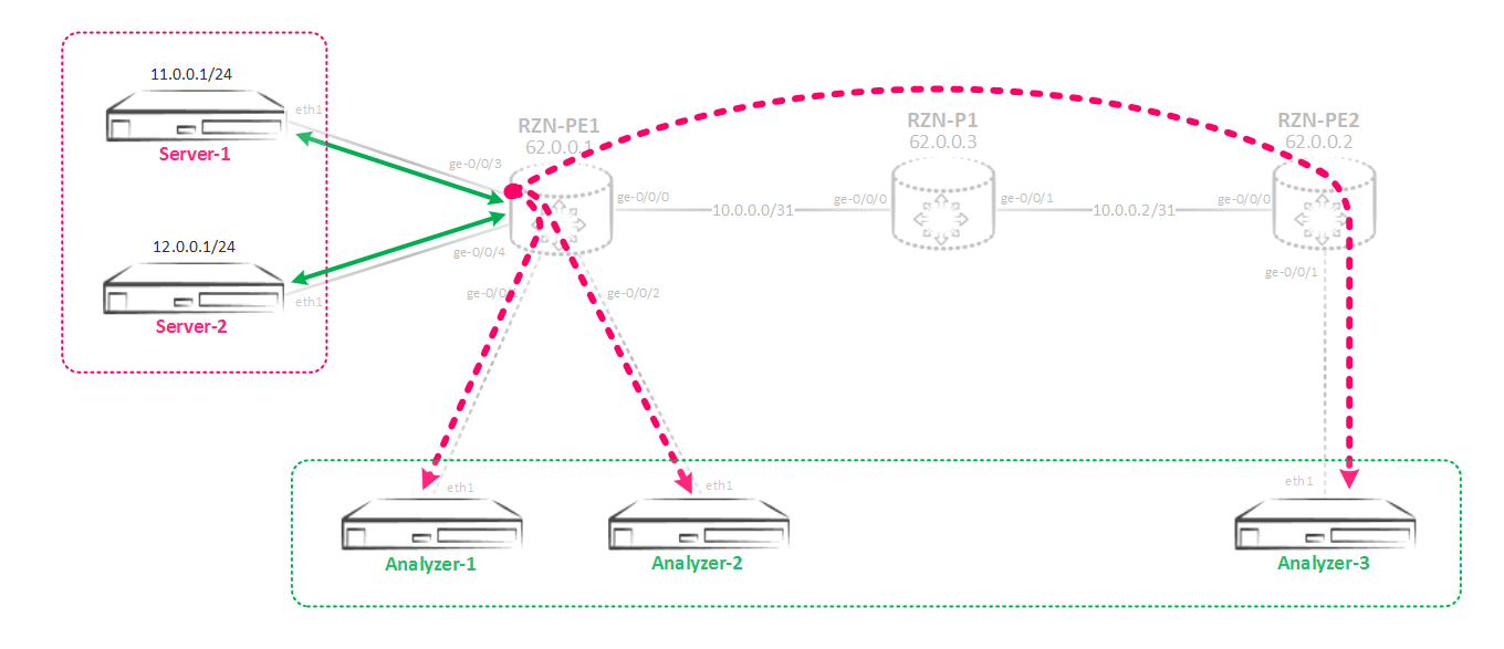
Our test bench will be constantly changing - we will add consumers, change their desires for the received copy of traffic, etc. At the first stage, the test bench looks like this:
Note: at first I wanted to use a traffic generator, but then I decided that the packets generated by hping3 tcp / udp / icmp caught on a traffic analyzer (as the analyzer was used simply on the host with ubuntu server 14.04 on board) would be more obvious than just counters from ports in pps (for example, you can compare the relevance of sent and received data). Counters should be used when carrying out load testing to check the performance of the router when using this functionality. But there is no point in checking the performance on the virtual MX - it’s still going to rest on the capabilities of the virusization server.
Suppose that there is some kind of traffic exchange between Server-1 (11.0.0.1) and Server-2 (12.0.0.1). The owners of the Analyzer-1 server want to see what exactly is transferred between these two servers, so we need to configure sending a copy of all traffic between Server-1 and Server-2 to Analyzer-1 — that is, do local mirroring. So let's get started.
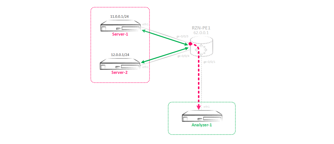
In theory, this should work like this: we create a mirroring instance in which we specify the parameters of the incoming traffic (how often the traffic is mirrored) and the outgoing parameters to which ports or ports to poison the traffic. In order to send traffic to the instance created by us, you need to interface or interfaces, from which (s) we want to remove a copy of the traffic, hang a special filter, which will turn our traffic into the required instance. That is, this is the classic scheme of policy base routing, or filter base routing in Juniper terms. We figured out the theory, now let's move on to practice - we need to build such a mirroring scheme:
First we need to create an instance in the hierarchy [edit forwarding-options port-mirroring], which we will use to mirror the traffic.
[edit forwarding-options port-mirroring] bormoglotx@RZN-PE-1# show instance { SPAN-1 { input { rate 1; run-length 0; } family inet { output { interface ge-0/0/1.0 { next-hop 169.254.0.1; } } } } The instance configuration consists of two parts. First, let's deal with the section of input - as it is not difficult to guess, these are the parameters of the incoming traffic, which must be mirrored. The rate and run-length parameters are important here. The first parameter is responsible for how often the packets will be mirrored (trigger trigger), the second parameter is responsible for how many packets will still be mirrored after triggering the trigger rate.
In our case, the rate is set to 1, that is, each package will be mirrored. Run-length is set to 0, since at a rate equal to 1 its presence does not play any role.
For completeness, we will analyze the meaning of these parameters in a more illustrative example. The rate parameter sets the frequency of traffic mirroring, suppose the rate is 5, that is, the trigger will be triggered on every 5th packet, which means every 5th packet will be mirrored. Now suppose the run-length is set to 4. This tells us that another 4 packets will be mirrored after every 5th packet. That is, the trigger first worked on the 5th packet - this packet will be mirrored, now another 4 packets, following the already mirrored one, will also be mirrored. As a result, we get that we mirror every 5th packet, plus 4 more packets following it - a total of 100% of the traffic. Changing these parameters can be mirrored, for example, every 10 packets out of 100 and so on (well, this is more necessary for sampling than mirroring, just the principle of operation is the same).
If we go back to our case, then we mirror every packet, so we simply don’t need the run-length parameter and leave the default value equal to zero.
To calculate the percentage of mirrored traffic, you can use the formula % = ((run-length + 1) / rate) * 100) . It is logical that with the parameters run-length 1 and rate 1, we get the mirroring of 200% of the traffic or, for example, with the rate 1 and run-length 4 - 500% of the traffic. I will disappoint or please you - more than 100% of traffic is not mirrored - Juniper packets will not multiply, which is more than logical. Yes, and come up with a script when you need to make two copies of the same traffic, I could not (if anyone knows - write in the comments).
And one more important parameter is maximum-packet-length. This is the maximum packet size that will be mirrored. If you set it to 128, for example, when you receive a packet that is more than 128 bytes (well, for example, 1514), the first 128 bytes will be cut off from it and sent to the consumer. The rest of the package will simply be dropped. This is convenient when you only need to send headers to the server and you do not need payloads. It is not recommended to install less than 20 for ipv4.
We now turn to the output parameters. Here, in general, we need to specify the interface to which we go to mirror traffic. In the case when we just have a p2p interface, we don’t need to specify anything else - everything will fly. But as we all remember, ethernet is far from p2p (to be precise, this is csma / cd), and in addition to the interface we need to specify the address of the host to which the traffic is intended, both IP and MAC (but before that we will get to it later ). I chose the address from the range of link-locale addresses to avoid any intersections with existing addresses - you can take any addressing, it absolutely does not change anything in the principle of the technology. In ethernet, in order to send a packet to a host, the router needs to find out the host’s MAC address using ARP. In my case, on the recipient server side, nothing is configured - just a blank interface and it turns out that the router will try in vain to resolve the address of the remote host. Naturally all the mirroring is over. How to be in this situation? All ingenious is simple - a static ARP entry is made:
bormoglotx@RZN-PE-1# show interfaces ge-0/0/1 description Analyzer-1; unit 0 { family inet { address 169.254.0.0/31 { arp 169.254.0.1 mac 02:00:00:00:00:01; } } } As a result, we will have the following entry on the interface:
[edit] bormoglotx@RZN-PE-1# run show arp interface ge-0/0/1.0 MAC Address Address Name Interface Flags 02:00:00:00:00:01 169.254.0.1 169.254.0.1 ge-0/0/1.0 permanent Here I would like to stay in more detail. Theoretically, you can send traffic to some real address configured on the server, but the simplest and most flexible approach is to create a fictitious IP address and ARP entry in the direction of the traffic consumer - that is, we simply make Juniper think that we have specified IP / MAC address, which ultimately causes the box to bluntly send traffic there without understanding, and whether there really is a specified host or not - the main thing is that the port was up. The use of static ARP recording in mirroring has a great advantage - static ARP recording does not become outdated, and the router will not send requests to the ARP server (which can fall into the dump of the removed traffic, which is not very good).
Now, in order for the traffic to become mirrored, we need to wrap it up in the instance we created. Filter base forwarding is used for this. We create a filter and apply it to the interface of interest to us:
[edit] bormoglotx@RZN-PE-1# show firewall family inet filter MIRROR>>>SPAN-1 term MIRROR { then port-mirror-instance SPAN-1; } [edit] bormoglotx@RZN-PE-1# show interfaces ge-0/0/3 description Server-1; unit 0 { family inet { filter { input MIRROR>>>SPAN-1; output MIRROR>>>SPAN-1; } address 11.0.0.254/24; } } Since we need to collect both incoming and outgoing traffic, we hang the filter on in both directions.
As practice shows, this filter does not block the passage of traffic between the servers themselves; therefore, it is not necessary to write an accept action, but for security it is often added.
Now you can check the status of the mirroring session:
bormoglotx@RZN-PE-1> show forwarding-options port-mirroring Instance Name: SPAN-1 Instance Id: 2 Input parameters: Rate : 1 Run-length : 0 Maximum-packet-length : 0 Output parameters: Family State Destination Next-hop inet up ge-0/0/1.0 169.254.0.1 Apparently mirroring in work. Now let's run 5 packages from Server-1 to Server-2 and see what we can catch on the Analyzer-1 analyzer:
bormoglotx@Server-1:~$ sudo hping3 -S -c 5 12.0.0.1 -d 40 -I eth1 HPING 12.0.0.1 (eth1 12.0.0.1): S set, 40 headers + 40 data bytes len=40 ip=12.0.0.1 ttl=63 DF id=34108 sport=0 flags=RA seq=0 win=0 rtt=3.4 ms len=40 ip=12.0.0.1 ttl=63 DF id=34121 sport=0 flags=RA seq=1 win=0 rtt=3.5 ms len=40 ip=12.0.0.1 ttl=63 DF id=34229 sport=0 flags=RA seq=2 win=0 rtt=3.5 ms len=40 ip=12.0.0.1 ttl=63 DF id=34471 sport=0 flags=RA seq=3 win=0 rtt=3.5 ms len=40 ip=12.0.0.1 ttl=63 DF id=34635 sport=0 flags=RA seq=4 win=0 rtt=3.5 ms --- 12.0.0.1 hping statistic --- 5 packets transmitted, 5 packets received, 0% packet loss Now let's see what we managed to do on the Analyzer-1 server:
bormoglotx@Analyzer-1:~$ sudo tcpdump -i eth1 tcpdump: verbose output suppressed, use -v or -vv for full protocol decode listening on eth1, link-type EN10MB (Ethernet), capture size 262144 bytes ^C 0 packets captured 0 packets received by filter 0 packets dropped by kernel Everything is not so rosy, it is clear from the conclusion that nothing actually works with us, although Juniper reported to us in the conclusion above that everything is ok. The fact is that the instance for mirroring can be created by ourselves (which we did) or use the default instance (it is one for the whole box). If we create the instance ourselves, then we must associate this instance with the FPC, on which we do peacekeeping (if ports on several FPC, it means to associate with several). Let's return to Juniper and specify the instance we created in the FPC configuration. Why did I emphasize this? The fact is that he stumbled upon it a couple of times and could not understand what the trick was - after all, the conclusions say that everything is fine.
[edit] bormoglotx@RZN-PE-1# show | compare [edit] + chassis { + fpc 0 { + port-mirror-instance SPAN-1; + } + } Now check again if the mirror works:
bormoglotx@Server-1:~$ sudo hping3 -S -c 5 12.0.0.1 -d 40 -I eth1 HPING 12.0.0.1 (eth1 12.0.0.1): S set, 40 headers + 40 data bytes len=40 ip=12.0.0.1 ttl=63 DF id=43901 sport=0 flags=RA seq=0 win=0 rtt=4.4 ms len=40 ip=12.0.0.1 ttl=63 DF id=44117 sport=0 flags=RA seq=1 win=0 rtt=3.4 ms len=40 ip=12.0.0.1 ttl=63 DF id=44217 sport=0 flags=RA seq=2 win=0 rtt=3.4 ms len=40 ip=12.0.0.1 ttl=63 DF id=44412 sport=0 flags=RA seq=3 win=0 rtt=3.7 ms len=40 ip=12.0.0.1 ttl=63 DF id=44416 sport=0 flags=RA seq=4 win=0 rtt=3.5 ms --- 12.0.0.1 hping statistic --- 5 packets transmitted, 5 packets received, 0% packet loss round-trip min/avg/max = 3.4/3.7/4.4 ms bormoglotx@Analyzer-1:~$ sudo tcpdump -i eth1 -B 4096 tcpdump: verbose output suppressed, use -v or -vv for full protocol decode listening on eth1, link-type EN10MB (Ethernet), capture size 262144 bytes 14:48:43.641475 IP 11.0.0.1.2237 > 12.0.0.1.0: Flags [S], seq 1075183755:1075183795, win 512, length 40 14:48:43.642024 IP 12.0.0.1.0 > 11.0.0.1.2237: Flags [R.], seq 0, ack 1075183796, win 0, length 0 14:48:44.641981 IP 11.0.0.1.2238 > 12.0.0.1.0: Flags [S], seq 1410214066:1410214106, win 512, length 40 14:48:44.642818 IP 12.0.0.1.0 > 11.0.0.1.2238: Flags [R.], seq 0, ack 1410214107, win 0, length 0 14:48:45.642022 IP 11.0.0.1.2239 > 12.0.0.1.0: Flags [S], seq 1858880488:1858880528, win 512, length 40 14:48:45.642873 IP 12.0.0.1.0 > 11.0.0.1.2239: Flags [R.], seq 0, ack 1858880529, win 0, length 0 14:48:46.642127 IP 11.0.0.1.2240 > 12.0.0.1.0: Flags [S], seq 1472273281:1472273321, win 512, length 40 14:48:46.642947 IP 12.0.0.1.0 > 11.0.0.1.2240: Flags [R.], seq 0, ack 1472273322, win 0, length 0 14:48:47.642017 IP 11.0.0.1.2241 > 12.0.0.1.0: Flags [S], seq 1810623498:1810623538, win 512, length 40 14:48:47.642601 IP 12.0.0.1.0 > 11.0.0.1.2241: Flags [R.], seq 0, ack 1810623539, win 0, length 0 ^C 10 packets captured 10 packets received by filter 0 packets dropped by kernel As a result, all traffic exchanges between Server-1 and Server-2 hit the analyzer, which is what we wanted.
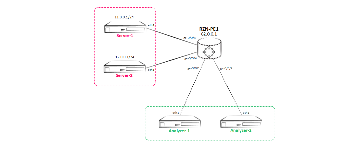
Moving on, our scheme has changed and now we have Analyzer-2, which also wants to receive all the traffic between Server-1 and Server-2:
Mirroring to two or more users
As a result, we have another task - we need to implement a new mirroring scheme, which looks like this:

It seems to be nothing complicated - let's create an interface in the direction of Analyzer-2, add it to the instance and it's in the bag.
[edit] bormoglotx@RZN-PE-1# show interfaces ge-0/0/2 description Analyzer-2; unit 0 { family inet { address 169.254.0.2/31 { arp 169.254.0.3 mac 02:00:00:00:00:01; } } } [edit] bormoglotx@RZN-PE-1# show forwarding-options port-mirroring instance SPAN-1 input { rate 1; run-length 0; } family inet { output { interface ge-0/0/1.0 { next-hop 169.254.0.1; } interface ge-0/0/2.0 { next-hop 169.254.0.3; } } } But when we try to add another port to the output hierarchy in the peacekeeping instance, we get an error when we commit:
[edit] bormoglotx@RZN-PE-1# commit check [edit forwarding-options port-mirroring instance SPAN-1 family inet output] Port-mirroring configuration error Port-mirroring out of multiple nexthops is not allowed on this platform error: configuration check-out failed A terrible at first glance phrase - platform restrictions do not allow us to establish two next-hop at once for mirrored traffic. But this restriction is very easy if we use next-hop groups.
I think it’s clear what the next-hop group is - the name speaks for itself. Juniper MX supports up to 30 next-hop groups, each of which can have up to 16 next-hop-in. But besides this, next-hop subgroups can be created in each next-hop group. In one next-hop group there should be at least two next-hop, otherwise JunOS will not allow to make a commit.
Now let's move on to the configuration, create a next-hop group:
[edit] bormoglotx@RZN-PE-1# show forwarding-options next-hop-group Analyzer-servers group-type inet; interface ge-0/0/1.0 { next-hop 169.254.0.1; } interface ge-0/0/2.0 { next-hop 169.254.0.3; } And now we will specify this group as next-hop in ouput:
[edit] bormoglotx@RZN-PE-1# show forwarding-options port-mirroring instance SPAN-1 input { rate 1; run-length 0; } family inet { output { next-hop-group Analyzer-servers; } } The rest of the config does not change.
Let's go to check. First, check the state of the next-hop group:
bormoglotx@RZN-PE-1> show forwarding-options next-hop-group detail Next-hop-group: Analyzer-servers Type: inet State: up Number of members configured : 2 Number of members that are up : 2 Number of subgroups configured : 0 Number of subgroups that are up : 0 Members Interfaces: State ge-0/0/1.0 next-hop 169.254.0.1 up ge-0/0/2.0 next-hop 169.254.0.3 up The group is fine - it is in work (the group will be in up if it has at least one interface in up). Now check the state of the mirroring session:
bormoglotx@RZN-PE-1> show forwarding-options port-mirroring SPAN-1 Instance Name: SPAN-1 Instance Id: 2 Input parameters: Rate : 1 Run-length : 0 Maximum-packet-length : 0 Output parameters: Family State Destination Next-hop inet up Analyzer-servers Everything is all right too, but as we have already seen earlier, this does not mean that we did everything right and everything will soar with us. Therefore, let us check whether traffic will be mirrored to our two servers:
bormoglotx@Server-1:~$ sudo hping3 -S -c 5 12.0.0.1 -d 40 -I eth1 HPING 12.0.0.1 (eth1 12.0.0.1): S set, 40 headers + 40 data bytes len=40 ip=12.0.0.1 ttl=63 DF id=64150 sport=0 flags=RA seq=0 win=0 rtt=3.4 ms len=40 ip=12.0.0.1 ttl=63 DF id=64222 sport=0 flags=RA seq=1 win=0 rtt=3.5 ms len=40 ip=12.0.0.1 ttl=63 DF id=64457 sport=0 flags=RA seq=2 win=0 rtt=3.7 ms len=40 ip=12.0.0.1 ttl=63 DF id=64593 sport=0 flags=RA seq=3 win=0 rtt=3.5 ms len=40 ip=12.0.0.1 ttl=63 DF id=64801 sport=0 flags=RA seq=4 win=0 rtt=3.4 ms --- 12.0.0.1 hping statistic --- 5 packets transmitted, 5 packets received, 0% packet loss round-trip min/avg/max = 3.4/3.5/3.7 ms Traffic to Analyzer-1:
bormoglotx@Analyzer-1:~$ sudo tcpdump -i eth1 -B 4096 tcpdump: verbose output suppressed, use -v or -vv for full protocol decode listening on eth1, link-type EN10MB (Ethernet), capture size 262144 bytes 15:09:36.837983 IP 11.0.0.1.2304 > 12.0.0.1.0: Flags [S], seq 1255230673:1255230713, win 512, length 40 15:09:36.839367 IP 12.0.0.1.0 > 11.0.0.1.2304: Flags [R.], seq 0, ack 1255230714, win 0, length 0 15:09:37.838115 IP 11.0.0.1.2305 > 12.0.0.1.0: Flags [S], seq 2135769685:2135769725, win 512, length 40 15:09:37.839054 IP 12.0.0.1.0 > 11.0.0.1.2305: Flags [R.], seq 0, ack 2135769726, win 0, length 0 15:09:38.838528 IP 11.0.0.1.2306 > 12.0.0.1.0: Flags [S], seq 1139555126:1139555166, win 512, length 40 15:09:38.839369 IP 12.0.0.1.0 > 11.0.0.1.2306: Flags [R.], seq 0, ack 1139555167, win 0, length 0 15:09:39.838328 IP 11.0.0.1.2307 > 12.0.0.1.0: Flags [S], seq 1181209811:1181209851, win 512, length 40 15:09:39.838924 IP 12.0.0.1.0 > 11.0.0.1.2307: Flags [R.], seq 0, ack 1181209852, win 0, length 0 15:09:40.838335 IP 11.0.0.1.2308 > 12.0.0.1.0: Flags [S], seq 1554756347:1554756387, win 512, length 40 15:09:40.838901 IP 12.0.0.1.0 > 11.0.0.1.2308: Flags [R.], seq 0, ack 1554756388, win 0, length 0 ^C 10 packets captured 10 packets received by filter 0 packets dropped by kernel And a similar copy of traffic on Analyzer-2:
bormoglotx@Analyzer-2:~$ sudo tcpdump -i eth1 -B 4096 tcpdump: verbose output suppressed, use -v or -vv for full protocol decode listening on eth1, link-type EN10MB (Ethernet), capture size 262144 bytes 15:09:35.125093 IP 11.0.0.1.2304 > 12.0.0.1.0: Flags [S], seq 1255230673:1255230713, win 512, length 40 15:09:35.126394 IP 12.0.0.1.0 > 11.0.0.1.2304: Flags [R.], seq 0, ack 1255230714, win 0, length 0 15:09:36.125044 IP 11.0.0.1.2305 > 12.0.0.1.0: Flags [S], seq 2135769685:2135769725, win 512, length 40 15:09:36.126107 IP 12.0.0.1.0 > 11.0.0.1.2305: Flags [R.], seq 0, ack 2135769726, win 0, length 0 15:09:37.125552 IP 11.0.0.1.2306 > 12.0.0.1.0: Flags [S], seq 1139555126:1139555166, win 512, length 40 15:09:37.126418 IP 12.0.0.1.0 > 11.0.0.1.2306: Flags [R.], seq 0, ack 1139555167, win 0, length 0 15:09:38.125374 IP 11.0.0.1.2307 > 12.0.0.1.0: Flags [S], seq 1181209811:1181209851, win 512, length 40 15:09:38.125930 IP 12.0.0.1.0 > 11.0.0.1.2307: Flags [R.], seq 0, ack 1181209852, win 0, length 0 15:09:39.125320 IP 11.0.0.1.2308 > 12.0.0.1.0: Flags [S], seq 1554756347:1554756387, win 512, length 40 15:09:39.125844 IP 12.0.0.1.0 > 11.0.0.1.2308: Flags [R.], seq 0, ack 1554756388, win 0, length 0 ^C 10 packets captured 10 packets received by filter 0 packets dropped by kernel Excellent - the task is completed, traffic flows to the right place - both consumers receive the requested copy of traffic.
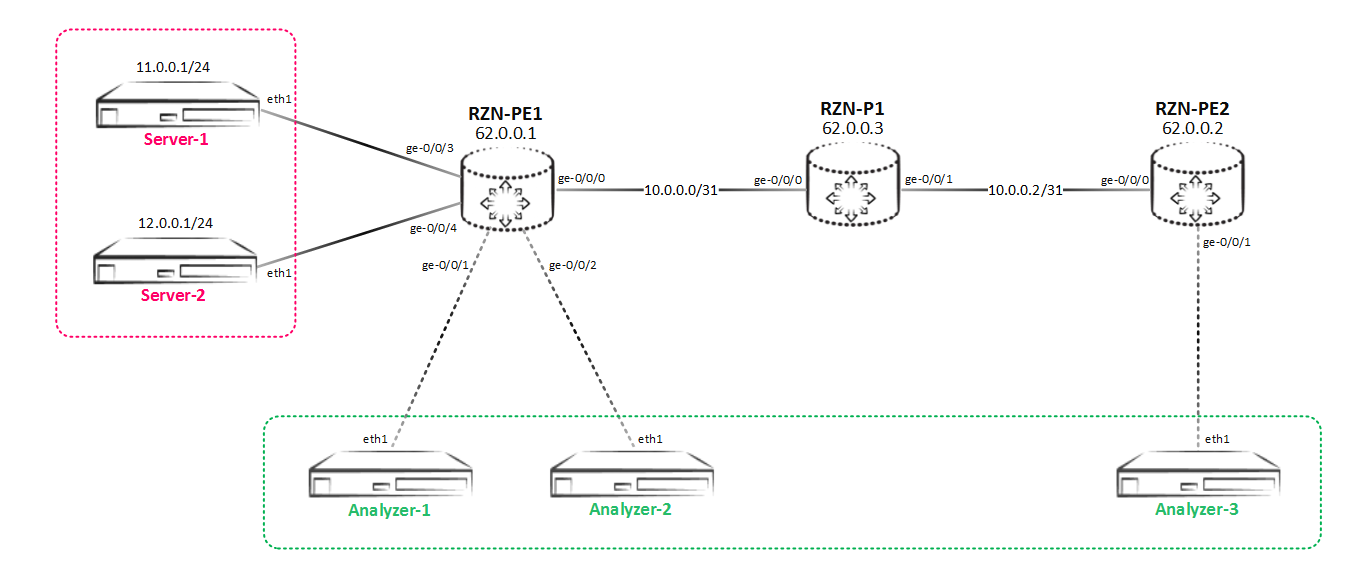
But the network is developing at a frantic pace, and our company doesn’t regret the money for scaling and SORM. Now we have another server - Analyzer-3, which also wants to receive a copy of the traffic. But the difficulty is that this server is not connected locally to our RZN-PE-1, but in RZN-PE-2:
Mirroring to a remote host
In the light of all that has been said, we need to redo the mirroring scheme again, now it will look like this:
Since the Analyzer-3 server is located behind RZN-PE-2, the methods we used to solve this problem earlier will not work. Our main problem is not how to mirror traffic, but how this already mirrored traffic is dragged to the Analyzer-3 server, which lives behind RZN-PE-2, and to do this transparently for the network, otherwise we will get problems (which see later). To do this, on the Juniper equipment it is common to use the gre tunnel. The idea is that we make a tunnel to a remote host and pack all the mirrored traffic into this tunnel and send it either directly to the server or to the router that terminates the traffic receiving server. You have two options for using the gre tunnel.
Option 1 . On the router that performs the mirroring, a gre tunnel is configured, and the destination itself is the address of the traffic receiving server. Naturally, the network in which this server is located (in our case it is Analyzer-3) must be known via any routing protocol (BGP or IGP is not important), otherwise gre tunnel simply does not take off. The problem is that in such a scenario, traffic to the server flows along with the gre headers. For modern traffic analysis and monitoring systems, this should not be a problem - gre is not IPSec and traffic is not encrypted. That is, on one side of the scale simplicity of implementation, on the second - an extra title. Perhaps in some scenarios, the presence of an extra header will not be acceptable, then you will have to use option 2.
Option 2 . Between the router that does the mirroring and the router that terminates the traffic receiving server, the tunnel goes gre (usually this is done on loopbacks). On the side of the router, which performs the mirroring from the source, everything is the same as it was in option 1, but on the recipient side, you need to set up an instance on the router that will mirror the traffic received from the gre tunnel in the direction of the analyzer. That is, for one mirror, we have to use one mirroring instance at the source and the second at the traffic recipient, which greatly complicates the scheme. But on the other hand, in this scenario, pure traffic flows to the server, without any extra gre headers. In addition, when implementing this scheme, there is a rule that must be strictly observed - the router that terminates the end point of the tunnel's gre should not have a route to the host, which will be specified as the recipient in the mirrored traffic (that is, the receiver of the original mirrored packet). If this condition is not met, then you will receive duplicate packets - the traffic will fly out of the gre tunnel and, in addition to being mirrored to the port you specified, will still be routed like a normal ip packet. And if the router knows the route to the destination host, then the traffic will be sent to it. To avoid this, the gre interface must be loaded into a separate instance with the type virtual-router, although there are other methods described below. If anyone is interested, then the configuration, the essence of the problem and how to win it under the spoiler:
Mirroring via gre problem
Configuration of the gre server side tunnel:
Only the destination address of the tunnel has changed - it has become a RZN-PE-2 loopback.
On the RZN-PE-2, you must first create a gre tunnel to RZN-PE-1:
In order to send traffic from this interface to the Mirroring instance now, we need to hang a filter on it that looks like this:
Well, the final touch is creating the instance itself, linking it to fpc and creating an interface to which traffic will be sent:
Now we’ll run the ping between Server-1 and Server-2 and verify that we mirrored:
I deleted some of the duplicates from the output, but their number can be seen - one valid packet and 41 doubles. On the traffic analyzer, you naturally see the same picture:
In addition to mirroring, the router also forwards the packet received from the gre tunnel, because it knows the route to the destination address. To fix this, we create an instance with the type of virtual router and add a gre interface and an interface to which we mirror traffic:
Run the ping again and check the performance of the circuit. Now on the server duplicates are not visible:
Well, the lack of duplicates proves a dump on the Analyzer-3 analyzer:
RZN-PE-2, . .
, discard ( discard, reject, Juniper icmp , )
, :
:
RZN-PE-2. next-hop ( , , , JunOS ), gre , next-hop :
Next-hop :
:
, , :
— . — .
bormoglotx@RZN-PE-1# show interfaces gr-0/0/0 description RSPAN; unit 0 { tunnel { source 62.0.0.1; destination 62.0.0.2; } family inet { address 169.254.100.1/31; } } Only the destination address of the tunnel has changed - it has become a RZN-PE-2 loopback.
On the RZN-PE-2, you must first create a gre tunnel to RZN-PE-1:
bormoglotx@RZN-PE-2> show configuration interfaces gr-0/0/0 description SPAN; unit 0 { tunnel { source 62.0.0.2; destination 62.0.0.1; } family inet { filter { input MIRROR-RSPAN-GE0/0/1; } } } In order to send traffic from this interface to the Mirroring instance now, we need to hang a filter on it that looks like this:
bormoglotx@RZN-PE-2> show configuration firewall family inet filter MIRROR-RSPAN-GE0/0/1 term MIRROR { then port-mirror-instance RSAPN; } Well, the final touch is creating the instance itself, linking it to fpc and creating an interface to which traffic will be sent:
bormoglotx@RZN-PE-2> show configuration forwarding-options port-mirroring instance RSAPN input { rate 1; } family inet { output { interface ge-0/0/1.0 { next-hop 169.254.100.1; } } } bormoglotx@RZN-PE-2> show configuration chassis fpc 0 { pic 0 { tunnel-services { bandwidth 10g; } } port-mirror-instance RSAPN; } bormoglotx@RZN-PE-2> show configuration interfaces ge-0/0/1 description Analyzer-3; unit 0 { family inet { address 169.254.100.0/31 { arp 169.254.100.1 mac 02:00:00:19:21:68; } } } Now we’ll run the ping between Server-1 and Server-2 and verify that we mirrored:
bormoglotx@Server-1:~$ ping 12.0.0.1 -I eth1 PING 12.0.0.1 (12.0.0.1) from 11.0.0.1 eth1: 56(84) bytes of data. 64 bytes from 12.0.0.1: icmp_seq=1 ttl=63 time=1.44 ms 64 bytes from 12.0.0.1: icmp_seq=1 ttl=60 time=3.24 ms (DUP!) … ... 64 bytes from 12.0.0.1: icmp_seq=1 ttl=3 time=34.7 ms (DUP!) ^C --- 12.0.0.1 ping statistics --- 1 packets transmitted, 1 received, +41 duplicates, 0% packet loss, time 0ms rtt min/avg/max/mdev = 1.444/17.916/34.712/9.126 ms I deleted some of the duplicates from the output, but their number can be seen - one valid packet and 41 doubles. On the traffic analyzer, you naturally see the same picture:
bormoglotx@Analyzer-3:~$ sudo tcpdump -i eth1 -B 9192 tcpdump: verbose output suppressed, use -v or -vv for full protocol decode listening on eth1, link-type EN10MB (Ethernet), capture size 262144 bytes 11:52:13.275451 IP 11.0.0.1 > 12.0.0.1: ICMP echo request, id 1601, seq 1, length 64 11:52:13.275462 IP 12.0.0.1 > 11.0.0.1: ICMP echo reply, id 1601, seq 1, length 64 11:52:13.276703 IP 12.0.0.1 > 11.0.0.1: ICMP echo reply, id 1601, seq 1, length 64 … … In addition to mirroring, the router also forwards the packet received from the gre tunnel, because it knows the route to the destination address. To fix this, we create an instance with the type of virtual router and add a gre interface and an interface to which we mirror traffic:
[edit] bormoglotx@RZN-PE-2# show routing-instances RSPAN-VR description "for RSPAN use only"; instance-type virtual-router; interface gr-0/0/0.0; interface ge-0/0/1.0; Run the ping again and check the performance of the circuit. Now on the server duplicates are not visible:
bormoglotx@Server-1:~$ ping 12.0.0.1 -I eth1 PING 12.0.0.1 (12.0.0.1) from 11.0.0.1 eth1: 56(84) bytes of data. 64 bytes from 12.0.0.1: icmp_seq=1 ttl=63 time=2.56 ms 64 bytes from 12.0.0.1: icmp_seq=2 ttl=63 time=8.13 ms 64 bytes from 12.0.0.1: icmp_seq=3 ttl=63 time=1.33 ms 64 bytes from 12.0.0.1: icmp_seq=4 ttl=63 time=2.09 ms 64 bytes from 12.0.0.1: icmp_seq=5 ttl=63 time=2.30 ms ^C --- 12.0.0.1 ping statistics --- 5 packets transmitted, 5 received, 0% packet loss, time 4006ms rtt min/avg/max/mdev = 1.332/3.288/8.137/2.459 ms Well, the lack of duplicates proves a dump on the Analyzer-3 analyzer:
bormoglotx@Analyzer-3:~$ sudo tcpdump -i eth1 -B 9192 tcpdump: verbose output suppressed, use -v or -vv for full protocol decode listening on eth1, link-type EN10MB (Ethernet), capture size 262144 bytes 11:59:12.605205 IP 11.0.0.1 > 12.0.0.1: ICMP echo request, id 1602, seq 1, length 64 11:59:12.605350 IP 12.0.0.1 > 11.0.0.1: ICMP echo reply, id 1602, seq 1, length 64 11:59:13.611070 IP 11.0.0.1 > 12.0.0.1: ICMP echo request, id 1602, seq 2, length 64 11:59:13.612356 IP 12.0.0.1 > 11.0.0.1: ICMP echo reply, id 1602, seq 2, length 64 11:59:14.606350 IP 11.0.0.1 > 12.0.0.1: ICMP echo request, id 1602, seq 3, length 64 11:59:14.606739 IP 12.0.0.1 > 11.0.0.1: ICMP echo reply, id 1602, seq 3, length 64 11:59:15.612423 IP 11.0.0.1 > 12.0.0.1: ICMP echo request, id 1602, seq 4, length 64 11:59:15.612488 IP 12.0.0.1 > 11.0.0.1: ICMP echo reply, id 1602, seq 4, length 64 11:59:16.614228 IP 11.0.0.1 > 12.0.0.1: ICMP echo request, id 1602, seq 5, length 64 11:59:16.614588 IP 12.0.0.1 > 11.0.0.1: ICMP echo reply, id 1602, seq 5, length 64 ^C 10 packets captured 10 packets received by filter 0 packets dropped by kernel RZN-PE-2, . .
, discard ( discard, reject, Juniper icmp , )
bormoglotx@RZN-PE-2# show firewall family inet filter MIRROR-RSPAN-GE0/0/1 term MIRROR { then { port-mirror-instance RSAPN; discard; } } , :
bormoglotx@Server-1:~$ ping 12.0.0.1 -I eth1 PING 12.0.0.1 (12.0.0.1) from 11.0.0.1 eth1: 56(84) bytes of data. 64 bytes from 12.0.0.1: icmp_seq=1 ttl=63 time=2.68 ms 64 bytes from 12.0.0.1: icmp_seq=2 ttl=63 time=1.22 ms 64 bytes from 12.0.0.1: icmp_seq=3 ttl=63 time=1.96 ms 64 bytes from 12.0.0.1: icmp_seq=4 ttl=63 time=2.30 ms 64 bytes from 12.0.0.1: icmp_seq=5 ttl=63 time=1.96 ms ^C --- 12.0.0.1 ping statistics --- 5 packets transmitted, 5 received, 0% packet loss, time 4005ms rtt min/avg/max/mdev = 1.220/2.028/2.685/0.487 ms :
bormoglotx@Analyzer-3:~$ sudo tcpdump -i eth1 -B 9192 tcpdump: verbose output suppressed, use -v or -vv for full protocol decode listening on eth1, link-type EN10MB (Ethernet), capture size 262144 bytes 12:03:11.934805 IP 11.0.0.1 > 12.0.0.1: ICMP echo request, id 1604, seq 1, length 64 12:03:11.934834 IP 12.0.0.1 > 11.0.0.1: ICMP echo reply, id 1604, seq 1, length 64 12:03:12.982685 IP 11.0.0.1 > 12.0.0.1: ICMP echo request, id 1604, seq 2, length 64 12:03:12.982716 IP 12.0.0.1 > 11.0.0.1: ICMP echo reply, id 1604, seq 2, length 64 12:03:13.935027 IP 11.0.0.1 > 12.0.0.1: ICMP echo request, id 1604, seq 3, length 64 12:03:13.935607 IP 12.0.0.1 > 11.0.0.1: ICMP echo reply, id 1604, seq 3, length 64 12:03:14.936859 IP 11.0.0.1 > 12.0.0.1: ICMP echo request, id 1604, seq 4, length 64 12:03:14.937654 IP 12.0.0.1 > 11.0.0.1: ICMP echo reply, id 1604, seq 4, length 64 12:03:15.937650 IP 11.0.0.1 > 12.0.0.1: ICMP echo request, id 1604, seq 5, length 64 12:03:15.938375 IP 12.0.0.1 > 11.0.0.1: ICMP echo reply, id 1604, seq 5, length 64 ^C 10 packets captured 10 packets received by filter 0 packets dropped by kernel RZN-PE-2. next-hop ( , , , JunOS ), gre , next-hop :
bormoglotx@RZN-PE-2> show configuration interfaces gr-0/0/0 description SPAN; unit 0 { tunnel { source 62.0.0.2; destination 62.0.0.1; } family inet { filter { input MIRROR-RSPAN-GE0/0/1; } } } bormoglotx@RZN-PE-2> show configuration firewall family inet filter MIRROR-RSPAN-GE0/0/1 term MIRROR { then next-hop-group Analyzer-3; } Next-hop :
bormoglotx@RZN-PE-2> show forwarding-options next-hop-group Analyzer-3 detail Next-hop-group: Analyzer-3 Type: inet State: up Number of members configured : 2 Number of members that are up : 1 Number of subgroups configured : 0 Number of subgroups that are up : 0 Members Interfaces: State ge-0/0/1.0 next-hop 169.254.100.1 up ge-0/0/100.0 down :
bormoglotx@Server-1:~$ ping 12.0.0.1 -I eth1 -c 5 PING 12.0.0.1 (12.0.0.1) from 11.0.0.1 eth1: 56(84) bytes of data. 64 bytes from 12.0.0.1: icmp_seq=1 ttl=63 time=3.38 ms 64 bytes from 12.0.0.1: icmp_seq=2 ttl=63 time=2.17 ms 64 bytes from 12.0.0.1: icmp_seq=3 ttl=63 time=2.14 ms 64 bytes from 12.0.0.1: icmp_seq=4 ttl=63 time=2.06 ms 64 bytes from 12.0.0.1: icmp_seq=5 ttl=63 time=1.89 ms --- 12.0.0.1 ping statistics --- 5 packets transmitted, 5 received, 0% packet loss, time 4006ms rtt min/avg/max/mdev = 1.891/2.332/3.387/0.538 ms , , :
bormoglotx@Analyzer-3:~$ sudo tcpdump -i eth1 -B 9192 tcpdump: verbose output suppressed, use -v or -vv for full protocol decode listening on eth1, link-type EN10MB (Ethernet), capture size 262144 bytes 12:19:28.306816 IP 11.0.0.1 > 12.0.0.1: ICMP echo request, id 1609, seq 1, length 64 12:19:28.306840 IP 12.0.0.1 > 11.0.0.1: ICMP echo reply, id 1609, seq 1, length 64 12:19:29.306887 IP 11.0.0.1 > 12.0.0.1: ICMP echo request, id 1609, seq 2, length 64 12:19:29.307273 IP 12.0.0.1 > 11.0.0.1: ICMP echo reply, id 1609, seq 2, length 64 12:19:30.308323 IP 11.0.0.1 > 12.0.0.1: ICMP echo request, id 1609, seq 3, length 64 12:19:30.308455 IP 12.0.0.1 > 11.0.0.1: ICMP echo reply, id 1609, seq 3, length 64 12:19:31.309897 IP 11.0.0.1 > 12.0.0.1: ICMP echo request, id 1609, seq 4, length 64 12:19:31.310117 IP 12.0.0.1 > 11.0.0.1: ICMP echo reply, id 1609, seq 4, length 64 12:19:32.313234 IP 11.0.0.1 > 12.0.0.1: ICMP echo request, id 1609, seq 5, length 64 12:19:32.313271 IP 12.0.0.1 > 11.0.0.1: ICMP echo reply, id 1609, seq 5, length 64 ^C 10 packets captured 10 packets received by filter 0 packets dropped by kernel — . — .
We will use the first option. First we need to enable tunnel services so that we have a gre interface (gr-X / X / X):
bormoglotx@RZN-PE-1# show chassis fpc 0 pic 0 { tunnel-services { bandwidth 10g; } } port-mirror-instance SPAN-1; Here it is worth going back a little to theory and talk about tunnel interfaces and resource reservations. In this configuration, I allocate 10G for tunnel services on a zero PIC of zero FPC. This does not mean that 10G of pfe bandwidth is cut off - this means that tunnel services can use no more than 10G of pfe bandwidth, and the part of resources not occupied by them can be used for forwarding traffic of physical ports - that is, 10G per pfe is flipped between tunnel services and real interfaces. But it is on MPC cards. If you are a “happy” DPC card holder (for example, you have a 4-dozen card), then with the above config you will lose one port (that is, the xe-port will simply disappear from the system and be unavailable from cli, and a light will come on near the port telling us that the port is in tunnel mode). Unfortunately,on these cards, as you understand, resources are reserved strictly, but these cards have long been outdated and gradually go out of fashion, although they are still in bulk.
Secondly, I would like to say about port numbering - if you reserve 1G, then the port number will be gr-0/0/10, if you reserve 10G or more, then the port number will be gr-0/0/0 (exactly this option).
[edit] bormoglotx@RZN-PE-1# run show interfaces terse | match "^(gr|lt|vt)-" gr-0/0/0 up up lt-0/0/0 up up vt-0/0/0 up up On line cards with a TRIO chipset, the maximum possible bandwidth reserved for tunnel services is 60G.
Note: I would like to add that lt and vt are different interfaces. lt - logical tunnel - a logical tunnel, which is intended, as a rule, for linking logical systems or routing of instances among themselves - it allows you to drive traffic between them, as if these instances or logical systems are connected by a direct patchcord. But vt is a virtual tunnel - a virtual loopback, which is not intended to bind any virtual entities, but to turn traffic on pfe for a repeated lookup (for example, in vpls).
After we created the tunnel interfaces, we had the opportunity to configure gr-0/0/0. Since we have torn out the option in which the remote PE router does not terminate the gre tunnel but simply sends traffic to the server, then as a sourse tunnel address on the RZN-PE-1, we specify our own loopback, and here is the destination address of the receiving server of the mirrored traffic and this address must be available.
As a matter of fact, the server may or may not have an address. You can select it yourself and make a static ARP entry, as shown below:
[edit] bormoglotx@RZN-PE-2# show | compare [edit interfaces] + ge-0/0/1 { + description Analyzer-3; + unit 0 { + family inet { + address 192.168.0.0/31 { + arp 192.168.0.1 mac 02:00:00:19:21:68; + } + } + } + } [edit protocols ospf area 0.0.0.0] interface ge-0/0/0.0 { ... } + interface ge-0/0/1.0 { + passive; + } Moreover, as can be seen from the presented configuration, the interface is added as passive to ospf, so that RZN-PE-1 knows the route to this network:
[edit] bormoglotx@RZN-PE-1# run show route 192.168.0.1 inet.0: 20 destinations, 20 routes (20 active, 0 holddown, 0 hidden) + = Active Route, - = Last Active, * = Both 192.168.0.0/31 *[OSPF/10] 00:00:16, metric 3 > to 10.0.0.0 via ge-0/0/0.0 Now we will create gre tunnel on RZN-PE-1 and add it to the next-hop group:
[edit] bormoglotx@RZN-PE-1# show interfaces gr-0/0/0 description RSPAN; unit 0 { tunnel { source 62.0.0.1; destination 192.168.0.1; } family inet { address 169.254.100.1/31; } } [edit] bormoglotx@RZN-PE-1# show forwarding-options next-hop-group Analyzer-servers group-type inet; interface gr-0/0/0.0; interface ge-0/0/1.0 { next-hop 169.254.0.1; } interface ge-0/0/2.0 { next-hop 169.254.0.3; } Unlike ge interfaces, the gre interface is p2p and therefore there is no point for the next-hop address for it - the traffic will still fly from the other end, although you can specify it.
Well, then everything is as usual - check the state of the session mirroring:
[edit] bormoglotx@RZN-PE-1# run show forwarding-options next-hop-group detail Next-hop-group: Analyzer-servers Type: inet State: up Number of members configured : 3 Number of members that are up : 3 Number of subgroups configured : 0 Number of subgroups that are up : 0 Members Interfaces: State gr-0/0/0.0 up ge-0/0/1.0 next-hop 169.254.0.1 up ge-0/0/2.0 next-hop 169.254.0.3 up Well, now let's check that the traffic on the remote server is obtained:
bormoglotx@Server-1:~$ sudo hping3 -S -c 5 12.0.0.1 -d 40 -I eth1 HPING 12.0.0.1 (eth1 12.0.0.1): S set, 40 headers + 40 data bytes len=40 ip=12.0.0.1 ttl=63 DF id=53439 sport=0 flags=RA seq=0 win=0 rtt=8.2 ms len=40 ip=12.0.0.1 ttl=63 DF id=53515 sport=0 flags=RA seq=1 win=0 rtt=3.5 ms len=40 ip=12.0.0.1 ttl=63 DF id=53610 sport=0 flags=RA seq=2 win=0 rtt=3.4 ms len=40 ip=12.0.0.1 ttl=63 DF id=53734 sport=0 flags=RA seq=3 win=0 rtt=3.8 ms len=40 ip=12.0.0.1 ttl=63 DF id=53897 sport=0 flags=RA seq=4 win=0 rtt=3.3 ms --- 12.0.0.1 hping statistic --- 5 packets transmitted, 5 packets received, 0% packet loss round-trip min/avg/max = 3.3/4.4/8.2 ms bormoglotx@Analyzer-3:~$ sudo tcpdump -i eth1 -B 4096 tcpdump: verbose output suppressed, use -v or -vv for full protocol decode listening on eth1, link-type EN10MB (Ethernet), capture size 262144 bytes 16:34:34.923370 IP 62.0.0.1 > 192.168.0.1: GREv0, length 84: IP 11.0.0.1.2894 > 12.0.0.1.0: Flags [S], seq 1149405522:1149405562, win 512, length 40 16:34:34.926586 IP 62.0.0.1 > 192.168.0.1: GREv0, length 44: IP 12.0.0.1.0 > 11.0.0.1.2894: Flags [R.], seq 0, ack 1149405563, win 0, length 0 16:34:35.923022 IP 62.0.0.1 > 192.168.0.1: GREv0, length 84: IP 11.0.0.1.2895 > 12.0.0.1.0: Flags [S], seq 1598018315:1598018355, win 512, length 40 16:34:35.923855 IP 62.0.0.1 > 192.168.0.1: GREv0, length 44: IP 12.0.0.1.0 > 11.0.0.1.2895: Flags [R.], seq 0, ack 1598018356, win 0, length 0 16:34:36.922903 IP 62.0.0.1 > 192.168.0.1: GREv0, length 84: IP 11.0.0.1.2896 > 12.0.0.1.0: Flags [S], seq 592229199:592229239, win 512, length 40 16:34:36.924048 IP 62.0.0.1 > 192.168.0.1: GREv0, length 44: IP 12.0.0.1.0 > 11.0.0.1.2896: Flags [R.], seq 0, ack 592229240, win 0, length 0 16:34:37.923278 IP 62.0.0.1 > 192.168.0.1: GREv0, length 84: IP 11.0.0.1.2897 > 12.0.0.1.0: Flags [S], seq 694611591:694611631, win 512, length 40 16:34:37.924765 IP 62.0.0.1 > 192.168.0.1: GREv0, length 44: IP 12.0.0.1.0 > 11.0.0.1.2897: Flags [R.], seq 0, ack 694611632, win 0, length 0 16:34:38.924275 IP 62.0.0.1 > 192.168.0.1: GREv0, length 84: IP 11.0.0.1.2898 > 12.0.0.1.0: Flags [S], seq 1423363395:1423363435, win 512, length 40 16:34:38.924291 IP 62.0.0.1 > 192.168.0.1: GREv0, length 44: IP 12.0.0.1.0 > 11.0.0.1.2898: Flags [R.], seq 0, ack 1423363436, win 0, length 0 ^C 10 packets captured 10 packets received by filter 0 packets dropped by kernel But, as I said, the gre traffic is the header, and if this is not a problem for your server, then this approach is the easiest and most flexible.
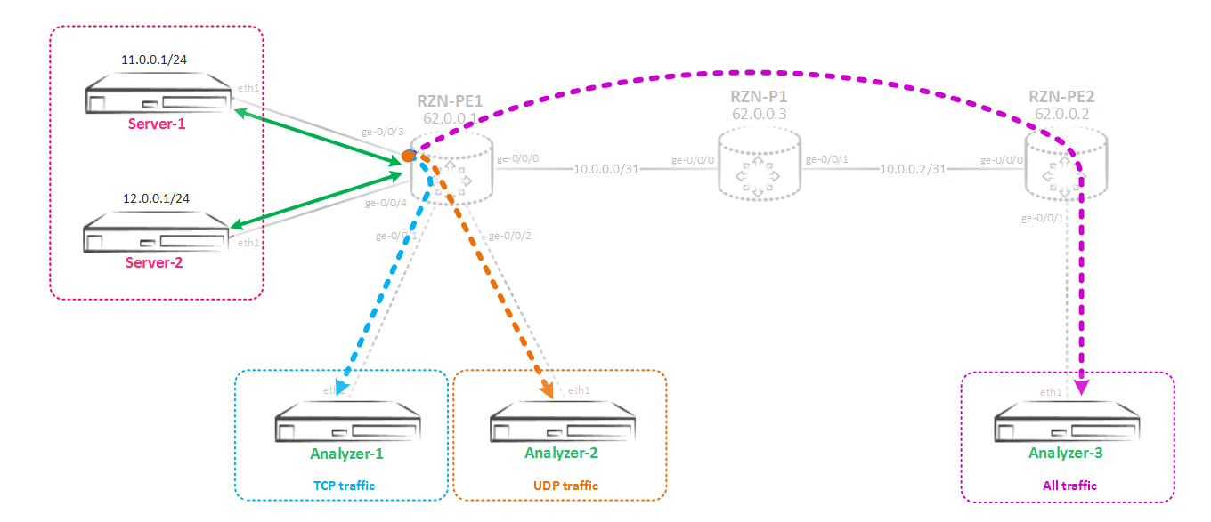
But as it turned out, now the owners of the recipient servers of mirrored traffic do not want to receive all the traffic, because it has become too much. The Analyzer-1 server needs only TCP traffic, the Analyzer-2 server only needs UDP traffic, but the Analyzer-3 server needs all traffic, not limited to TCP / UDP. That is, now we need to implement such a scheme:
Selective mirroring for two or more consumers
Here we need a vt-0/0/0 tunnel interface (virtual loopback) or you can use lt-0/0/0 (virtual tunnel), but the first one is more preferable. So, the concept of selective mirroring is as follows: first, the traffic from the port is mirrored to the virtual loopback vt-port, and then scattered from this port using a filter to different next-hop groups based on the parameters you have selected - protocols, ports, etc. For Better understanding of what is happening, let's now collect this scheme. First, change the mirroring instance so that the traffic is mirrored into a virtual loopback:
[edit] bormoglotx@RZN-PE-1# show forwarding-options port-mirroring instance SPAN-1 input { rate 1; run-length 0; } family inet { output { interface vt-0/0/0.0; no-filter-check; } } The no-filter-check parameter is very important - this command allows us to attach a filter to the interface to which traffic is mirrored. By default, filtering on these interfaces is prohibited. Now create the vt-interface itself:
[edit] bormoglotx@RZN-PE-1# show interfaces vt-0/0/0 unit 0 { description SPAN-USE; family inet; } You cannot attach any addresses to this interface, and the family of addresses that can be allowed on it is limited.
Now we have the following picture - all traffic from the interface ge-0/0/3 is sent to the port vt-0/0 / 0.0. Now we need to mirror this traffic in the direction of different consumers. To do this, you first need to create next-hop groups, which include the necessary consumers:
[edit] bormoglotx@RZN-PE-1# show forwarding-options next-hop-group Analyzer-TCP group-type inet; interface gr-0/0/0.0; interface ge-0/0/1.0 { next-hop 169.254.0.1; } [edit] bormoglotx@RZN-PE-1# show forwarding-options next-hop-group Analyzer-UDP group-type inet; interface gr-0/0/0.0; interface ge-0/0/2.0 { next-hop 169.254.0.3; } [edit] bormoglotx@RZN-PE-1# show forwarding-options next-hop-group Analyzer-default group-type inet; interface gr-0/0/0.0; interface ge-0/0/100.0; The gr-0/0/0 interface, which is designed to mirror traffic to the Analyzer-3, has been added to all three groups. This is done because this server wants to receive both TCP and UDP traffic, and you cannot make a separate group for it and then apply it in the filter. Using the same next-hop in different groups is not prohibited. In the Analyzer-default group there is also a port ge-0/0 / 100.0 - this is a fake port added to the group in order to be able to commit the configuration - since there must be at least two interfaces in the group.
Now we need to create a filter that will match traffic according to the criteria we need and scatter to next-hop groups:
[edit] bormoglotx@RZN-PE-1# show firewall family inet filter MIRROR-SORTED term MIRROR-TCP { from { protocol tcp; } then next-hop-group Analyzer-TCP; } term MIRROR-UDP { from { protocol udp; } then next-hop-group Analyzer-UDP; } term MIRROR-DEFAUL { then next-hop-group Analyzer-default; } And attach it to the vt interface:
[edit] bormoglotx@RZN-PE-1# show interfaces vt-0/0/0 unit 0 { description SPAN-USE; family inet { filter { input MIRROR-SORTED; } } } We check our design. Mirroring in vt interface in up state:
bormoglotx@RZN-PE-1> show forwarding-options port-mirroring SPAN-1 Instance Name: SPAN-1 Instance Id: 2 Input parameters: Rate : 1 Run-length : 0 Maximum-packet-length : 0 Output parameters: Family State Destination Next-hop inet up vt-0/0/0.0 All groups are in operation (remember that at least one port must be in up in order for the group to become up):
bormoglotx@RZN-PE-1> show forwarding-options next-hop-group detail Next-hop-group: Analyzer-TCP Type: inet State: up Number of members configured : 2 Number of members that are up : 2 Number of subgroups configured : 0 Number of subgroups that are up : 0 Members Interfaces: State gr-0/0/0.0 up ge-0/0/1.0 next-hop 169.254.0.1 up Next-hop-group: Analyzer-UDP Type: inet State: up Number of members configured : 2 Number of members that are up : 2 Number of subgroups configured : 0 Number of subgroups that are up : 0 Members Interfaces: State gr-0/0/0.0 up ge-0/0/2.0 next-hop 169.254.0.3 up Next-hop-group: Analyzer-default Type: inet State: up Number of members configured : 2 Number of members that are up : 1 Number of subgroups configured : 0 Number of subgroups that are up : 0 Members Interfaces: State gr-0/0/0.0 up ge-0/0/100.0 down Well, now let's generate 5 icmp, tcp and udp packages and see what server it goes to. On all client servers we will enable tcpdump at the same time. I used hping3 with the --rand-source switch, so we will not see reverse traffic, since only traffic on the port is removed towards Server-1.
So, we look at what we caught on the Analyzer-1, there should be only TCP:
bormoglotx@Analyzer-1:~$ sudo tcpdump -i eth1 -B 9192 tcpdump: verbose output suppressed, use -v or -vv for full protocol decode listening on eth1, link-type EN10MB (Ethernet), capture size 262144 bytes 19:58:25.457641 IP 108.215.126.169.1668 > 12.0.0.1.0: Flags [S], seq 1842749676:1842749716, win 512, length 40 19:58:26.458098 IP 230.181.170.188.1669 > 12.0.0.1.0: Flags [S], seq 1810452177:1810452217, win 512, length 40 19:58:27.459245 IP 112.6.155.46.1670 > 12.0.0.1.0: Flags [S], seq 1524555644:1524555684, win 512, length 40 19:58:28.459006 IP 50.45.169.23.1671 > 12.0.0.1.0: Flags [S], seq 1362080290:1362080330, win 512, length 40 19:58:29.459294 IP 135.146.14.177.1672 > 12.0.0.1.0: Flags [S], seq 2122009219:2122009259, win 512, length 40 ^C 5 packets captured 5 packets received by filter 0 packets dropped by kernel Now let's check what we've got on Analyzer-2 (there should be only UDP traffic here):
bormoglotx@Analyzer-2:~$ sudo tcpdump -i eth1 -B 9192 tcpdump: verbose output suppressed, use -v or -vv for full protocol decode listening on eth1, link-type EN10MB (Ethernet), capture size 262144 bytes 19:58:09.340702 IP 132.43.66.243.1121 > 12.0.0.1.0: UDP, length 40 19:58:10.341308 IP 205.172.124.143.1122 > 12.0.0.1.0: UDP, length 40 19:58:11.341239 IP 253.127.33.120.1123 > 12.0.0.1.0: UDP, length 40 19:58:12.341204 IP 246.68.75.25.1124 > 12.0.0.1.0: UDP, length 40 19:58:13.341819 IP 95.89.126.64.1125 > 12.0.0.1.0: UDP, length 40 ^C 5 packets captured 5 packets received by filter 0 packets dropped by kernel Well, I stayed on Analyzer-3, there we catch everything, the total number of packets should be 15 (5 UDP / 5 TCP / 5 ICMP):
bormoglotx@Analyzer-3:~$ sudo tcpdump -i eth1 -B 9192 tcpdump: verbose output suppressed, use -v or -vv for full protocol decode listening on eth1, link-type EN10MB (Ethernet), capture size 262144 bytes 19:58:11.782669 IP 62.0.0.1 > 192.168.0.1: GREv0, length 72: IP 132.43.66.243.1121 > 12.0.0.1.0: UDP, length 40 19:58:12.783508 IP 62.0.0.1 > 192.168.0.1: GREv0, length 72: IP 205.172.124.143.1122 > 12.0.0.1.0: UDP, length 40 19:58:13.783166 IP 62.0.0.1 > 192.168.0.1: GREv0, length 72: IP 253.127.33.120.1123 > 12.0.0.1.0: UDP, length 40 19:58:14.782758 IP 62.0.0.1 > 192.168.0.1: GREv0, length 72: IP 246.68.75.25.1124 > 12.0.0.1.0: UDP, length 40 19:58:15.783594 IP 62.0.0.1 > 192.168.0.1: GREv0, length 72: IP 95.89.126.64.1125 > 12.0.0.1.0: UDP, length 40 19:58:18.310249 IP 62.0.0.1 > 192.168.0.1: GREv0, length 100: IP 65.173.140.215 > 12.0.0.1: ICMP net 5.6.7.8 unreachable, length 76 19:58:19.311045 IP 62.0.0.1 > 192.168.0.1: GREv0, length 100: IP 171.91.95.222 > 12.0.0.1: ICMP net 5.6.7.8 unreachable, length 76 19:58:20.312496 IP 62.0.0.1 > 192.168.0.1: GREv0, length 100: IP 228.215.127.12 > 12.0.0.1: ICMP net 5.6.7.8 unreachable, length 76 19:58:21.311067 IP 62.0.0.1 > 192.168.0.1: GREv0, length 100: IP 214.149.191.71 > 12.0.0.1: ICMP net 5.6.7.8 unreachable, length 76 19:58:22.311398 IP 62.0.0.1 > 192.168.0.1: GREv0, length 100: IP 119.130.166.53 > 12.0.0.1: ICMP net 5.6.7.8 unreachable, length 76 19:58:26.186528 IP 62.0.0.1 > 192.168.0.1: GREv0, length 84: IP 108.215.126.169.1668 > 12.0.0.1.0: Flags [S], seq 1842749676:1842749716, win 512, length 40 19:58:27.187385 IP 62.0.0.1 > 192.168.0.1: GREv0, length 84: IP 230.181.170.188.1669 > 12.0.0.1.0: Flags [S], seq 1810452177:1810452217, win 512, length 40 19:58:28.188726 IP 62.0.0.1 > 192.168.0.1: GREv0, length 84: IP 112.6.155.46.1670 > 12.0.0.1.0: Flags [S], seq 1524555644:1524555684, win 512, length 40 19:58:29.188846 IP 62.0.0.1 > 192.168.0.1: GREv0, length 84: IP 50.45.169.23.1671 > 12.0.0.1.0: Flags [S], seq 1362080290:1362080330, win 512, length 40 19:58:30.188499 IP 62.0.0.1 > 192.168.0.1: GREv0, length 84: IP 135.146.14.177.1672 > 12.0.0.1.0: Flags [S], seq 2122009219:2122009259, win 512, length 40 ^C 15 packets captured 15 packets received by filter 0 packets dropped by kernel Well, all that had to be implemented - done - traffic is mirrored and scattered across consumers, as was intended.
Above, we mirrored L3 traffic, but Juniper MX-series routers are very flexible devices and they allow not only IP traffic to be mirrored (inet / inet6 family), but also L2 traffic, for example, vpls or l2ckt (xconnect in Cisco terms).
Local mirroring of L2 traffic
Consider the simplest case when you need to spy on what is being transmitted in L2CKT (this is certainly not good, because the client whose traffic you are going to the analyzer does not even know about, and you should do such things only with the consent of customer). The scheme is simple - some L2CKT is stretched between RZN-PE-1 and RZN-PE-2:

That is, we need to implement such a mirroring scheme:
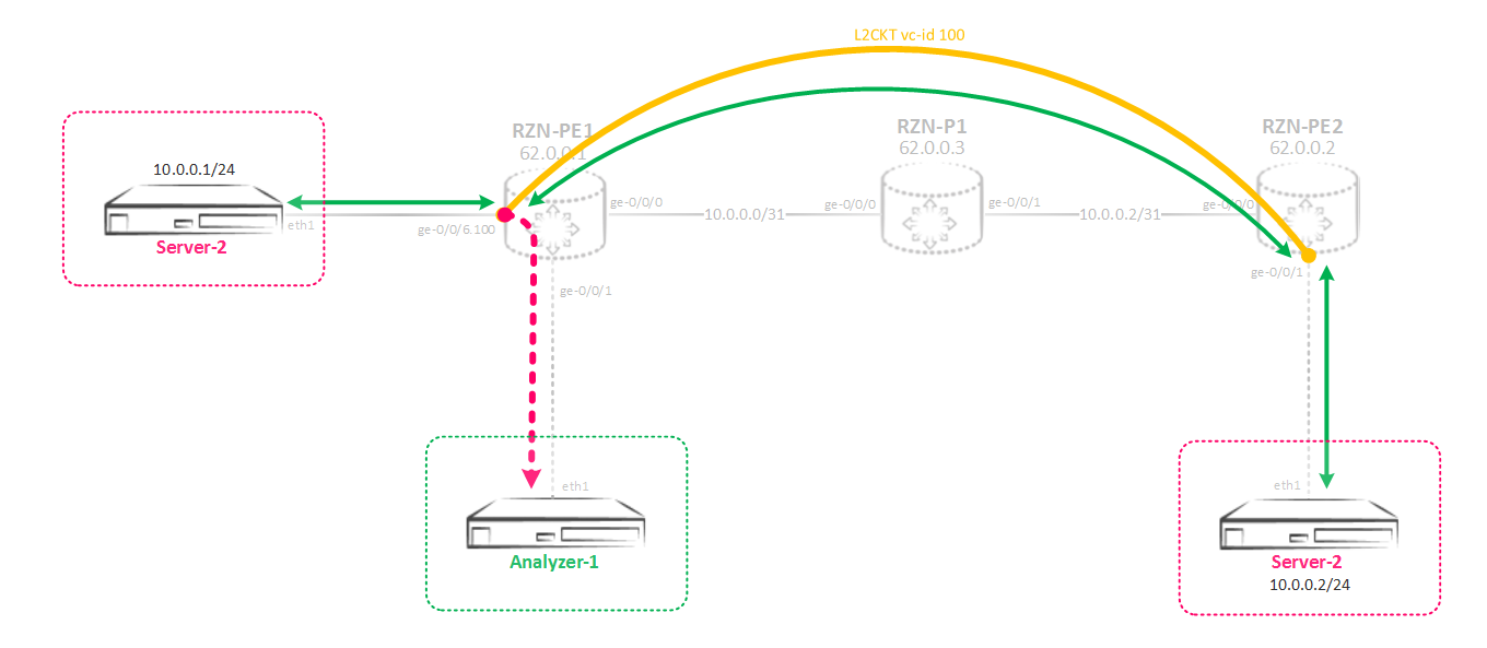
Between the RZN-PE-1 and the RZN-PE-2 there is a tensioned L2CKT, which we want to listen to:
bormoglotx@RZN-PE-1> show configuration protocols l2circuit neighbor 62.0.0.2 { interface ge-0/0/6.100 { virtual-circuit-id 100; } } bormoglotx@RZN-PE-1> show configuration interfaces ge-0/0/6.100 encapsulation vlan-ccc; vlan-id 100; family ccc { filter { input MIRROR-L2CKT-SPAN-1; output MIRROR-L2CKT-SPAN-1; } } It is logical that the ccc family is enabled on the interface - this is L2CKT as it does. In the configuration on the interface we need, the filter is already hung in both directions - since we want to receive all the traffic that will pass through our L2CKT. The filter is essentially the same as it was before, only the address family is not inet, but ccc:
bormoglotx@RZN-PE-1> show configuration firewall family ccc filter MIRROR-L2CKT-SPAN-1 term MIRROR { then port-mirror-instance SPAN-1; } Next, set up a mirroring instance that we want to use for mirroring. There are no changes in the input section - everything is as before, but in the output section there are significant differences:
bormoglotx@RZN-PE-1> show configuration forwarding-options port-mirroring instance SPAN-1 input { rate 1; run-length 0; } family ccc { output { interface ge-0/0/1.0; } } We have changed the address family - now it's ccc. It pulls inevitable changes in the configuration of the interface to which we want to send traffic. If we try to set some next-hop address, as was done earlier on a non-p2p interface, then we will fail:
bormoglotx@RZN-PE-1# set forwarding-options port-mirroring instance SPAN-1 family ccc output interface ge-0/0/1 ? Possible completions: <[Enter]> Execute this command + apply-groups Groups from which to inherit configuration data + apply-groups-except Don't inherit configuration data from these groups no-filter-check Do not check for filters on port-mirroring interface | Pipe through a command We simply do not have such an opportunity. Therefore, on the interface to which we need to send traffic, we need to include the bridge or ccc family:
[edit] bormoglotx@RZN-PE-1# show interfaces ge-0/0/1 description Analyzer-1; encapsulation ethernet-ccc; unit 0 { family ccc; } The ccc family is naturally simpler to use, but if you need to use a bridge, do not forget about an important nuance - the interface with encapsulation of the bridge should be placed in the bridge domain (the vlan number in the domain can be used zero (none), so you will not select real vlan numbers for mirroring other services).
Everything is ready, check the status of the mirroring session:
bormoglotx@RZN-PE-1> show forwarding-options port-mirroring Instance Name: SPAN-1 Instance Id: 2 Input parameters: Rate : 1 Run-length : 0 Maximum-packet-length : 0 Output parameters: Family State Destination Next-hop ccc up ge-0/0/1.0 Everything is fine - session up. Now we’ll run a ping between our hosts and check what we can build on the analyzer:
bormoglotx@TEST-1> ping routing-instance VR-1 10.0.0.2 count 5 PING 10.0.0.2 (10.0.0.2): 56 data bytes 64 bytes from 10.0.0.2: icmp_seq=0 ttl=64 time=10.159 ms 64 bytes from 10.0.0.2: icmp_seq=1 ttl=64 time=11.136 ms 64 bytes from 10.0.0.2: icmp_seq=2 ttl=64 time=9.723 ms 64 bytes from 10.0.0.2: icmp_seq=3 ttl=64 time=7.754 ms 64 bytes from 10.0.0.2: icmp_seq=4 ttl=64 time=10.619 ms --- 10.0.0.2 ping statistics --- 5 packets transmitted, 5 packets received, 0% packet loss round-trip min/avg/max/stddev = 7.754/9.878/11.136/1.162 ms Here is what happened to collect:
bormoglotx@Analyzer-1:~$ sudo tcpdump -i eth1 -B 9192 tcpdump: verbose output suppressed, use -v or -vv for full protocol decode listening on eth1, link-type EN10MB (Ethernet), capture size 262144 bytes 23:44:31.948237 IP 10.0.0.1 > 10.0.0.2: ICMP echo request, id 17420, seq 0, length 64 23:44:31.954408 IP 10.0.0.2 > 10.0.0.1: ICMP echo reply, id 17420, seq 0, length 64 23:44:32.955149 IP 10.0.0.1 > 10.0.0.2: ICMP echo request, id 17420, seq 1, length 64 23:44:32.964115 IP 10.0.0.2 > 10.0.0.1: ICMP echo reply, id 17420, seq 1, length 64 23:44:33.967789 IP 10.0.0.1 > 10.0.0.2: ICMP echo request, id 17420, seq 2, length 64 23:44:33.973388 IP 10.0.0.2 > 10.0.0.1: ICMP echo reply, id 17420, seq 2, length 64 23:44:34.975442 IP 10.0.0.1 > 10.0.0.2: ICMP echo request, id 17420, seq 3, length 64 23:44:34.980370 IP 10.0.0.2 > 10.0.0.1: ICMP echo reply, id 17420, seq 3, length 64 23:44:35.986900 IP 10.0.0.1 > 10.0.0.2: ICMP echo request, id 17420, seq 4, length 64 23:44:35.992213 IP 10.0.0.2 > 10.0.0.1: ICMP echo reply, id 17420, seq 4, length 64 ^C 10 packets captured 10 packets received by filter 0 packets dropped by kernel Actually all the packages got to the analyzer, which is what we wanted.
Now let's look at a more complicated scheme - we need to configure mirroring for interfaces located in the bridge domain or in a virtual switch, the method of sending a copy is not to some local port, as we did above, but to send this traffic to the remote box.
Mirroring L2 traffic to a remote server
The first thought is simple, you can use the gre tunnel. But, unfortunately, gre does not support ccc / tcc / vpls / bridge encapsulation. But in Junos there are a lot of different tools that allow you to solve the same task using different methods, and sometimes it seems that doing something is not realistic, but in the end, through the N-th amount of time and the N-th number of smoked manuals, everything takes off. Here as well. Now we will collect such a complex scheme:
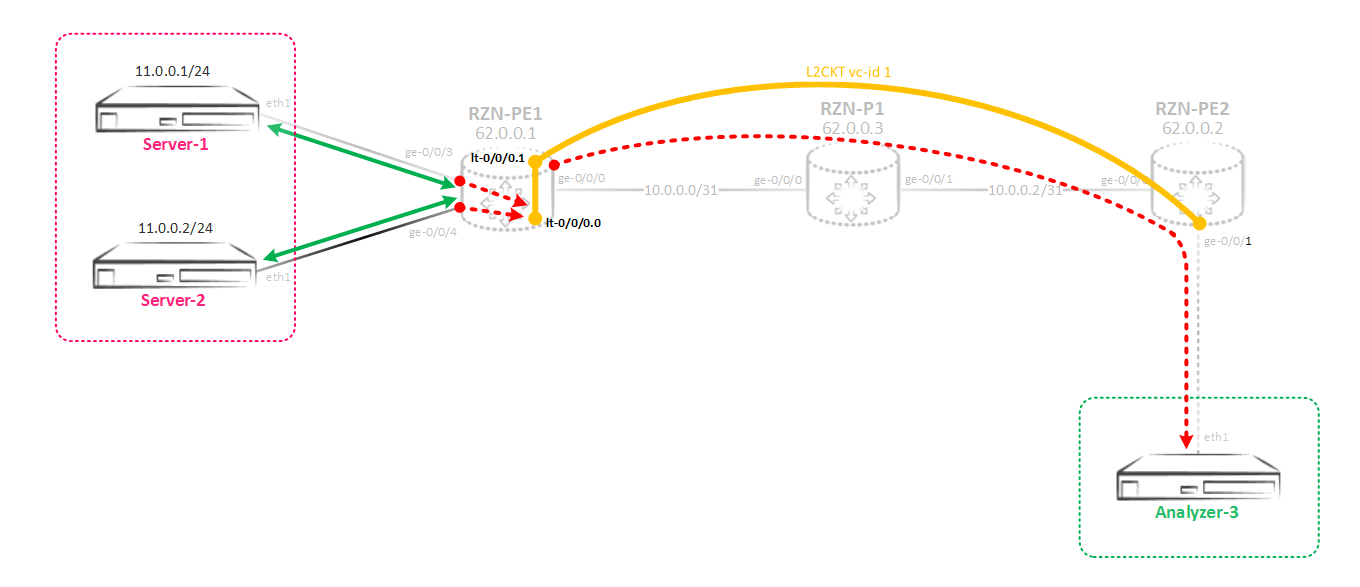
I will explain what and why. So, we mirror the traffic from the virtual switch (L2CKT or bridge domain) to the peacekeeping instance, and the traffic is not mirrored to any physical interface, but to the virtual tunnel interface lt-0/0/0. This interface is alone on the box and its units are created in pairs called peer-units — one unit is the input end of the tunnel, the second unit is the output one. As a result, all that falls into one unit will fly out of the second unit associated with it and vice versa. On this interface, we will enable ccc encapsulation and build L2CKT from it to a remote router that terminates the traffic receiving server — that is, we simply give L2 traffic through L2CKT straight to the remote server. For a remote marshurtizer, this will be a simple L2CKT.
We now turn to configuration. Interfaces in the direction of servers in access, and are located in a virtual switch:
bormoglotx@RZN-PE-1# wildcard range show interfaces ge-0/0/[3-4] description Server-1; encapsulation ethernet-bridge; unit 0 { family bridge { filter { input MIRROR-BRIDGE-vSwitch-1; } interface-mode access; vlan-id 100; } } description Server-2; encapsulation ethernet-bridge; unit 0 { family bridge { filter { input MIRROR-BRIDGE-vSwitch-1; } interface-mode access; vlan-id 100; } } [edit] bormoglotx@RZN-PE-1# show routing-instances vSwitch-1 instance-type virtual-switch; interface ge-0/0/3.0; interface ge-0/0/4.0; bridge-domains { BD100 { vlan-id 100; } } Filters are hung on the interfaces to mirror incoming traffic to the SPAN-1 instance. The filter is no different from the previously used ones, except for the family — in this scenario, the bridge is used:
[edit] bormoglotx@RZN-PE-1# show firewall family bridge filter MIRROR-BRIDGE-vSwitch-1 term MIRROR { then port-mirror-instance SPAN-1; } Now create the instance SPAN-1:
[edit] bormoglotx@RZN-PE-1# show forwarding-options port-mirroring instance SPAN-1 input { rate 1; run-length 0; } family vpls { output { interface lt-0/0/0.0; } } There is a little nuance.The address family is not specified as a bridge - you will not even find such a family in the instance configuration, but vpls. This family (VPLS) is used to mirror traffic from vpls / bridge domains.
Next, create a tunnel interface to which we want to send traffic:
[edit] bormoglotx@RZN-PE-1# show interfaces lt-0/0/0 unit 0 { description RSPAN-IN; encapsulation ethernet-ccc; peer-unit 1; family ccc; } unit 1 { description RSPAN-OUT; encapsulation ethernet-ccc; peer-unit 0; family ccc; } As I wrote earlier, the lt interface consists of two units - in our case, units 0 and 1. Everything that flies into unit 0 will fly out through unit 1. Generally, on the one hand, a unit can be like L3, for example inet, and on the other, like L2, for example ccc - and it will work. We have ccc at both ends, on the zero unit this is due to the fact that traffic must be mirrored to the instance with the ccc / bridge / vpls family, and the use of ccc on the first unit is due to the fact that L2CKT is being built from this unit.
Next, create a L2CKT between RZN-PE-1 and RZN-PE-2. From RZN-PE-1:
[edit] bormoglotx@RZN-PE-1# show protocols l2circuit neighbor 62.0.0.2 { interface lt-0/0/0.1 { virtual-circuit-id 1; encapsulation-type ethernet; } } From RZN-PE-2:
bormoglotx@RZN-PE-2> show configuration protocols l2circuit neighbor 62.0.0.1 { interface ge-0/0/1.0 { virtual-circuit-id 1; encapsulation-type ethernet; } } bormoglotx@RZN-PE-2> show configuration interfaces ge-0/0/1 description Analyzer-3; encapsulation ethernet-ccc; unit 0 { family ccc; } Now you can check whether our "Frankenstein". First, look at the L2CKT state:
[edit] bormoglotx@RZN-PE-1# run show l2circuit connections | find ^Nei Neighbor: 62.0.0.2 Interface Type St Time last up # Up trans lt-0/0/0.1(vc 1) rmt Up Sep 2 07:28:05 2017 1 Remote PE: 62.0.0.2, Negotiated control-word: Yes (Null) Incoming label: 299840, Outgoing label: 299872 Negotiated PW status TLV: No Local interface: lt-0/0/0.1, Status: Up, Encapsulation: ETHERNET Flow Label Transmit: No, Flow Label Receive: No Great, L2CKT at work. Next, check the status of the mirroring session:
[edit] bormoglotx@RZN-PE-1# run show forwarding-options port-mirroring SPAN-1 Instance Name: SPAN-1 Instance Id: 2 Input parameters: Rate : 1 Run-length : 0 Maximum-packet-length : 0 Output parameters: Family State Destination Next-hop vpls up lt-0/0/0.0 Everything is fine, now let's start ping between the Server-1 and Server-2 servers and see what happens to the traffic analyzer:
bormoglotx@Server-1:~$ ping 11.0.0.2 -I 11.0.0.1 -c 5 -i 0.2 PING 11.0.0.2 (11.0.0.2) from 11.0.0.1 : 56(84) bytes of data. 64 bytes from 11.0.0.2: icmp_seq=1 ttl=64 time=3.86 ms 64 bytes from 11.0.0.2: icmp_seq=2 ttl=64 time=2.34 ms 64 bytes from 11.0.0.2: icmp_seq=3 ttl=64 time=2.30 ms 64 bytes from 11.0.0.2: icmp_seq=4 ttl=64 time=9.56 ms 64 bytes from 11.0.0.2: icmp_seq=5 ttl=64 time=1.43 ms --- 11.0.0.2 ping statistics --- 5 packets transmitted, 5 received, 0% packet loss, time 803ms rtt min/avg/max/mdev = 1.436/3.903/9.565/2.937 ms Now go to Analyzer-3 and see what got into tcpdump:
bormoglotx@Analyzer-3:~$ sudo tcpdump -i eth1 -B 9192 tcpdump: verbose output suppressed, use -v or -vv for full protocol decode listening on eth1, link-type EN10MB (Ethernet), capture size 262144 bytes 10:48:46.296920 IP 11.0.0.1 > 11.0.0.2: ICMP echo request, id 2000, seq 1, length 64 10:48:46.297969 IP 11.0.0.2 > 11.0.0.1: ICMP echo reply, id 2000, seq 1, length 64 10:48:46.496380 IP 11.0.0.1 > 11.0.0.2: ICMP echo request, id 2000, seq 2, length 64 10:48:46.497647 IP 11.0.0.2 > 11.0.0.1: ICMP echo reply, id 2000, seq 2, length 64 10:48:46.700540 IP 11.0.0.1 > 11.0.0.2: ICMP echo request, id 2000, seq 3, length 64 10:48:46.700547 IP 11.0.0.2 > 11.0.0.1: ICMP echo reply, id 2000, seq 3, length 64 10:48:46.897518 IP 11.0.0.1 > 11.0.0.2: ICMP echo request, id 2000, seq 4, length 64 10:48:46.907024 IP 11.0.0.2 > 11.0.0.1: ICMP echo reply, id 2000, seq 4, length 64 10:48:47.098414 IP 11.0.0.1 > 11.0.0.2: ICMP echo request, id 2000, seq 5, length 64 10:48:47.098799 IP 11.0.0.2 > 11.0.0.1: ICMP echo reply, id 2000, seq 5, length 64 10:48:51.307134 ARP, Request who-has 11.0.0.1 tell 11.0.0.2, length 46 10:48:51.307542 ARP, Reply 11.0.0.1 is-at 00:50:01:00:07:00 (oui Unknown), length 46 ^C 12 packets captured 12 packets received by filter 0 packets dropped by kernel Well, besides our pings, the arp request-response also got into the dump, which proves that all traffic is mirrored, which is what we need.
Well, in conclusion, I remember that I wrote that you can bind a maximum of two mirroring instances on the same fpc. But what if you need to use three instances?
Of course, you can use two user-defined instances and a default instance (which is only one), but firstly, this is not the best solution, but secondly, what to do if the default instance is already taken? Naturally JunOS allows you to bypass this limitation. In principle, there is nothing supernatural here - the principle of operation is the same, the changes concern only the configuration of the instances.
Using more than two mirroring instances on one FPC
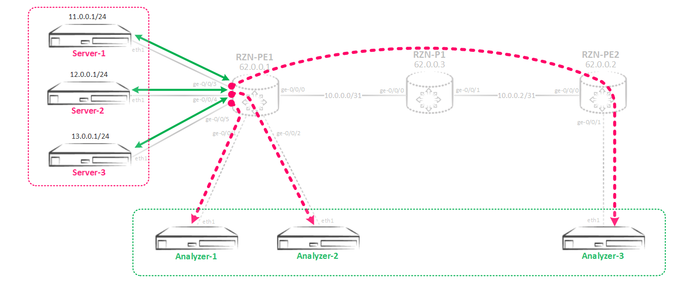
So, the main point in creating a bundle between several mirroring instances: the parent instance and the child instances that refer to it are made. In the parent instance, we specify the input parameters - that is, the speed of mirroring / sampling, the maximum packet size. In the child instances, the output parameters are specified - interfaces or the next-hop group, but the input parameters are inherited from the parent instance specified in the configuration. Without configs, this is clearly incomprehensible, so let's put together a mirroring scheme:
First, create a parent instance, I just called it SPAN.
bormoglotx@RZN-PE-1# show forwarding-options port-mirroring instance SPAN input { rate 1; run-length 0; } Instance shows only incoming parameters of mirroring. Nothing more to specify here.
Now create three child instances:
[edit] bormoglotx@RZN-PE-1# show forwarding-options port-mirroring instance SPAN-1 input-parameters-instance SPAN; family inet { output { interface ge-0/0/1.0 { next-hop 169.254.0.1; } } } [edit] bormoglotx@RZN-PE-1# show forwarding-options port-mirroring instance SPAN-2 input-parameters-instance SPAN; family inet { output { interface ge-0/0/2.0 { next-hop 169.254.0.3; } } } [edit] bormoglotx@RZN-PE-1# show forwarding-options port-mirroring instance SPAN-3 input-parameters-instance SPAN; family inet { output { interface gr-0/0/0.0 { } } Here we already indicate the outgoing parameters of mirroring. The connection between the parent and child instances occurs using the following command:
input-parameters-instance SPAN; As a result, all three SPAN-1/2/3 instances created by me will inherit the input parameters from the SPAN instance. As you remember, now we need to bind the instances to some kind of (or some sort, if the incoming ports on different cards) are FPC. As I said earlier, only the parent instance must be bound to the FPC:
bormoglotx@RZN-PE-1# show chassis fpc 0 pic 0 { tunnel-services { bandwidth 10g; } } port-mirror-instance SPAN; Well, then everything is the same - we create filters and hang them on the incoming ports:
bormoglotx@RZN-PE-1# wildcard range show interfaces ge-0/0/[3-5] description Server-1; unit 0 { family inet { filter { input MIRROR>>>SPAN-3; output MIRROR>>>SPAN-3; } address 11.0.0.254/24; } } description Server-2; unit 0 { family inet { filter { input MIRROR>>>SPAN-2; output MIRROR>>>SPAN-2; } address 12.0.0.254/24; } } description Server-3; unit 0 { family inet { filter { input MIRROR>>>SPAN-1; output MIRROR>>>SPAN-1; } address 13.0.0.254/24; } } I pay attention that in filters not parent instance, but child instances are specified:
[edit] bormoglotx@RZN-PE-1# wildcard range show firewall family inet filter MIRROR>>>SPAN-[1-3] term MIRROR { then port-mirror-instance SPAN-1; } term MIRROR { then port-mirror-instance SPAN-2; } term MIRROR { then port-mirror-instance SPAN-3; } Now check the state of the mirroring sessions:
bormoglotx@RZN-PE-1# run show forwarding-options port-mirroring Instance Name: SPAN-1 Instance Id: 3 Input parameters: Rate : 1 Run-length : 0 Maximum-packet-length : 0 Output parameters: Family State Destination Next-hop inet up gr-0/0/0.0 Instance Name: SPAN-2 Instance Id: 4 Input parameters: Rate : 1 Run-length : 0 Maximum-packet-length : 0 Output parameters: Family State Destination Next-hop inet up ge-0/0/2.0 169.254.0.3 Instance Name: SPAN-3 Instance Id: 5 Input parameters: Rate : 1 Run-length : 0 Maximum-packet-length : 0 Output parameters: Family State Destination Next-hop inet up ge-0/0/1.0 169.254.0.1 From the output, it is clear that traffic mirroring sessions are in operation, and the parameters for processing incoming traffic are inherited from the parent instance. Actually I will not show the conclusions of the work directly in order to shorten the article - I think that after reading this article you will be able to assemble such a scheme yourself and test its performance.
It seems that everything I wanted to write - wrote. If there are comments or additions - write.
Thanks for attention.
Source: https://habr.com/ru/post/336978/
All Articles