The practice of forming requirements in IT projects from A to Z. Part 3. System Functions and Project Boundaries
All parts
Part 1. Introduction
Part 2. Goals and Needs
Part 3. System Functions and Project Boundaries
Part 4. Business processes automated by the system.
Part 5. Essence of the subject area and a little about strategies
Part 6. Behavior of the system. Excellence requirements
Part 7. The transfer of requirements in production. Conclusion
VI Define system functions and project boundaries.
Each model is limited in its answers, but there is no restriction on how and what the model is modeling, as there is no restriction on human thought.
Douglas T. Ross

When the basic needs of users are collected and agreed with all the participants, we can begin to identify the key functions of the developed system, and on the basis of them estimate the cost and duration of the project aimed at creating the final product. As a result of this process, as a rule, it turns out that there is not enough time, or resources, or both, to obtain a qualitative result within the stipulated time frame. In this case, the ability to effectively determine the boundaries of the project and manage them is very useful.
The purpose of this group of works: to determine as fully as possible the set of functions that the target product should perform to meet the identified needs of the customer Select those that can be implemented in the framework of the current project.
The boundaries of the project (project scope) show what area of the final product will be implemented in the current project. In other words, a line is defined between what we will do now and what we will postpone for later or from which we will be able to refuse. To do this, the team’s arsenal should have a tool that allows not only to build models of the product being created, but to help visually outline the framework of automated processes, as well as provide the ability to easily take processes abroad or turn them back on. This is very important for awareness and better planning of the scope of work. Such a tool is useful not only for the "struggle" with the exorbitant desires of the customer, but also for the management maneuvers of the developers.
It is very convenient to use functional or process modeling for managing the project Borders, both at the initial stages and during the whole project. Models of this type allow to describe the events and the sequence of execution of Business processes in time.
')
Sometimes, to define boundaries, a group of developers tries not to use functions, but entities of the subject domain. I want to warn you against this approach, as it is fraught with the following consequences:
- due to insufficient formalization, some processes may not be fully implemented, and this will be revealed only when the first versions of the product are released;
- some automated processes will not be used due to the fact that the related processes in the project are not implemented;
- some objects of the system will not be used, because there are no processes that process them.
Figure 6.1 shows the process of formalizing the requirements for the target system, supplemented by a subprocess of determining the functions that it should perform.
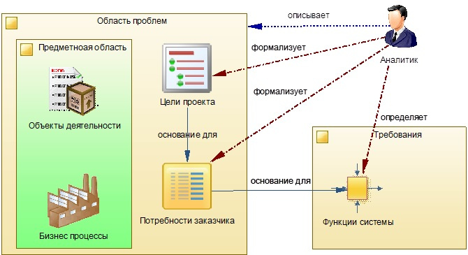
Figure 6.1 - Model of the function definition process
1. Use IDEF0 notation to define system functions and project boundaries
The most convenient method of functional modeling, in terms of defining the boundaries of the project, in my opinion is the “good old” design methodology SADT, which uses top-down hierarchical decomposition. The use of IDEF0 diagrams has the following advantages over analogues:
- Decomposition in the analysis of automated processes is performed from top to bottom - from one of the highest level to its constituent subprocesses. Sequential branching processes with clarification of their layer by layer, allows on the one hand, not to miss important business processes from the team’s field of view, and on the other to always work with one selected node containing a small number of elements;
- The method of modeling, in which the incoming data streams and the influences controlling them are taken as a basis, makes it possible to accurately and fully identify all the subprocesses enclosed in the process that process these incoming data and provide the output - the outgoing flow;
- Mandatory for each result of the process (outgoing flow) - the comparison of another process that consumes it at the input (as an incoming flow), allows you not to miss the functions in the chain of data processing and conversion.
Using the IDEF0 standard, a model is constructed that describes the main functions performed by the system and their interaction in the form of information flows, including the external environment. Thus, IDEF0 diagrams easily read the boundaries of the system and its environment. Another advantage of diagrams of this type, as mentioned above, is that instead of developing one large, cumbersome model, several small, relatively simple models nested inside each other like matryoshka are created in stages.
Thus, the structure of a complex process is represented as an abstraction of high-level functions, which is decomposed into more detailed processes, increasing the degree of accuracy, layer by layer.
This type of simulation will also allow us to identify the processes that were released from the field of view at the previous stages.
If at the stage of process modeling there are found processes that are not described at the stage of collecting information, we will have to return to the stage of forming User stories again and fill the gap. And now, so that all this clutter of information is better settled in the mind, let's look at a specific example.
2. Example description of the “Requirements Management” function
I want to remind the basic tenets of the IDEFO standard. The graphic design of the standard consists of: the concept of “Work” (Activity) for designating an action, presented in the form of a block; Four interface types: “Input” (Input), “Output” (Output), “Control” (Control) and “Mechanism” (Mechanism), presented in the form of arcs. The left side of the unit is intended for the inputs, the top for control, the right for outputs, and the bottom for mechanisms. For a more detailed study of this topic, refer to [2].
In the first step of the simulation, it is necessary to determine all the data streams entering the system from outside (input signals). In our case it is:
- Project objectives;
- Project participants and stakeholders;
- Requirements of participants to the functionality of the target product of the project;
- Requirements Development Techniques;
Next, we define all the “products” generated by the system for external use (output signals):
- Project artifacts, including Requirements, Models, Plans, etc;
- Target product of the project.
The data flows described above and the global abstract function of the system that processes these flows are displayed in the Diagram, see Fig. 6.2.
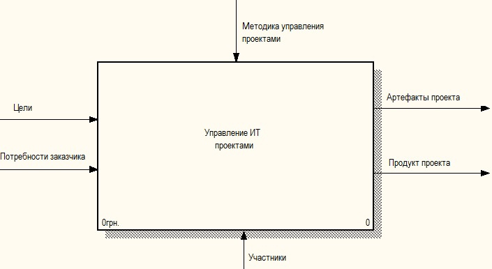
Fig.6.2 - Functional model of the Management System requirements of the upper level
Falling inside the function (the “Work” block) we get to the next level of abstraction of the system functionality. At the beginning we see only the data streams identified at the previous stage (level), see fig. 6.3.
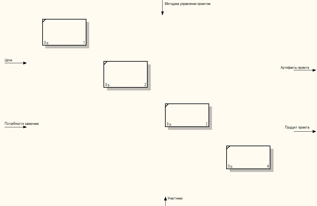
Fig.6.3 - Getting started on detailing the IT Project Management function
For each such flow, it is necessary to define a process that processes (transforms) or uses it, adding new “Jobs” blocks (functions) associated with it in the diagram.
Thus, at each subsequent step (falling into the process) it is necessary: for each data stream identified at the previous level, to associate the function (process) for its processing. As a result of such a simulation, we obtain a list of functions that detail the higher abstract process, see Fig. 6.3.
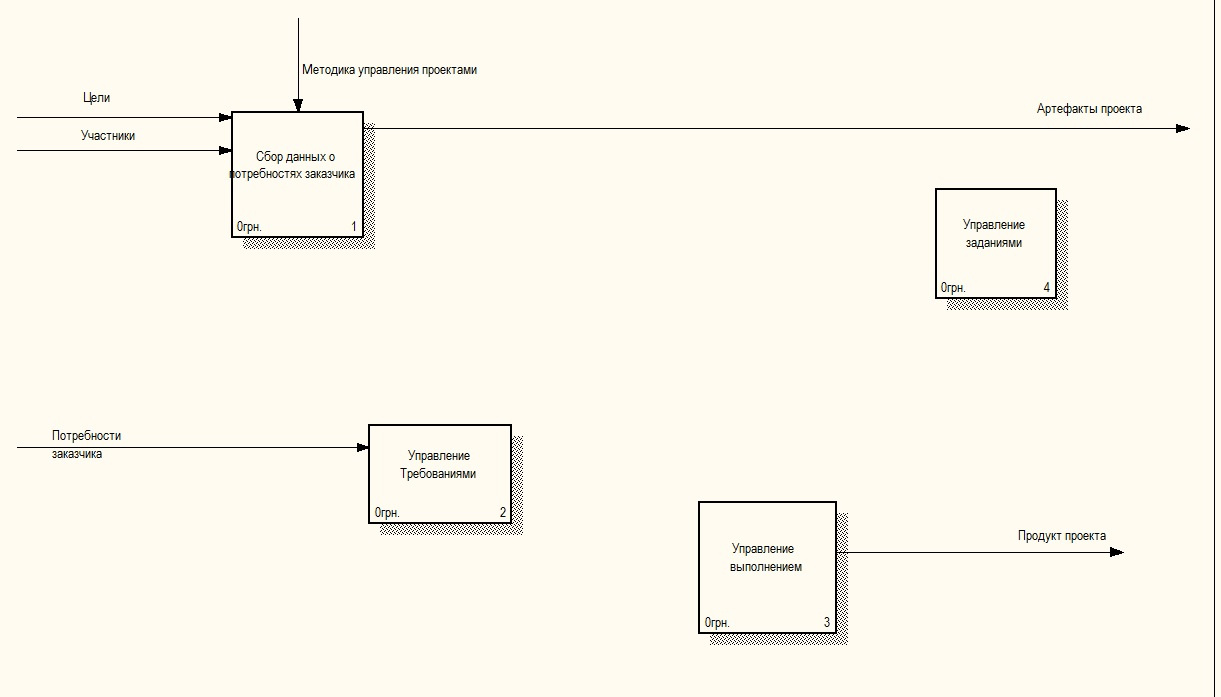
Fig.6.4 - Definition of subprocesses for the IT Project Management function
In our project, according to the data flows outlined in Chapter IV and the data flows identified at the first stage, the following group of processes should be automated:
- Collecting data on customer needs for product functionality;
- Accounting system requirements for the target product;
- Managing a pool of works aimed at implementing system requirements and, as a result, at creating a target product;
- Accounting for the implementation of work on the implementation of system requirements and, as a result, the project’s progress towards the goal;
One “Task Management” process does not receive data from outside of us and does not provide anything to the external environment. It turns out - it is an auxiliary process that ensures the functioning of others. He still stands apart, see fig. 6.4.
Since most processes are logically interconnected, it is necessary to establish all the data streams that provide these links. Thus arcs appear from function to function in the diagram. Later, each such arc (link), included in the block “Works”, should, when modeling the next nested level, “get” its own processing process.
An example of a model of these functions with already established relationships is displayed in the Diagram, see Fig. 6.5.
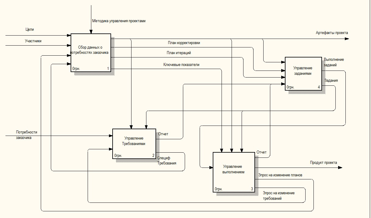
Fig.6.5 - Requirements Management System Functional Model
If such diagrams are used in the document, it is necessary to accompany them with a detailed description. The following is an example description:
The figure shows that the functional architecture of our project is presented in the form of four domains:
- Collect customer needs. A group of processes for recording and analyzing the goals of product development, the main scenarios for its use, and the actors - users of the product.
- Requirements specification management. The processes of formation of functional requirements based on the identified needs of the customer and future users of the target product.
- Management of the formation of tasks. The processes of formation of tasks aimed at meeting the identified needs of the customer, through the implementation of functional requirements. Fixing the results, when tasks are executed by the performers, by changing the state of the requirements for which it is formed.
- Execution Management. Processes that monitor and fix the increment of functionality that allows you to realize the needs of users in the target product.
In the first functional block “A1”, as input parameters, we will send data on the goals and wishes of the customer, stakeholders, etc. The data comes from the external environment of the system in the form of documents - requests for development or orally. The purpose of the process is to convert them into information suitable for transfer to the “A2” block - “Management of requirements specifications”. The result of the activity of the first block, in the form of User stories and reports, is also suitable for external use and is available to external systems and users in the form of printed forms or export data to files. Therefore, the arrow from the block is divided and extends beyond the border of the diagram, to the higher function.
From the diagram it is clear that the “A1” block has feedback from the “A2” block, in the form of control information, bringing about the degree of implementation of the requirements formed by User Stories (the “Report on the implementation of requirements” arc). This link allows you to track the progress and completeness of the implementation of user history in the final product through the chain, through the specification of requirements.
The second block, as shown in the diagram, receives as input the processed wishes of the customer in the form of User stories, user needs, etc. already in a formalized form. Based on these data, it forms the functional requirements for the product being developed and formalizes them in the form of requirements specifications. Further, these specifications are transmitted to the fourth block “A4”, which is responsible for setting the task for the performers for their implementation. It can be seen from the diagram that tasks can be set for performing work with requirements (the “Task” arc, which is included in the “A2” unit as a control). Please note that data on the execution of tasks according to specifications is returned to the second functional unit, which allows determining the increment of functionality obtained in the course of development in this domain.
From the block “A2”, as the control instructions, we will send the key indicators of the specifications to the third block. On the basis of them, it is possible to determine the degree of achievement of a given functionality, using a report on the performance of the rear set up for performers set by these specifications. The report comes in the form of input parameters from the “A4” block.
Despite all my efforts, this section has turned out to be difficult and tedious. But to understand the concept it was important to figure out how it all works. Further, we will describe the nested functions is not so detailed.
3. An example of the description of the function “Collecting customer needs”
We continue decomposition of the identified functions, decomposing each domain into smaller, detailed functions. To do this, use our User stories (they were discussed in the previous part of the publication). When describing them, we will determine how fully we “cover” the customer’s needs with them.
Let's look at block A1 in Figure 6.4, which represents the “Customer needs gathering” domain. Its details are shown in figure 6.5. All data streams that were included in block 1 in Figure 6.4, respectively, were included in the diagram that details it, see fig. 6.6.

Fig. 6.6 - Domain Scheme Collect Customer Needs
Functionally, we have divided the domain into four processes:
- Interviewing customers and users of the target product. The process of fixing a user story, including its purpose. Checks for the existence of similar stories recorded earlier. Conflicting scenarios are identified. This block should “cover” User stories US01, US02
- Change user history. The process of managing changes in describing the needs of a customer of a product, including initiating the process of changing the system requirements associated with it This block should “cover” US02 User Stories.
- Fixation of project stakeholders. All persons somehow connected with the project are identified. This process should “cover” US04 User Stories.
- Determination of the level of implementation of user history. Monitoring of system requirements related to user history is carried out, their current states and the level of implementation within the framework of the final product are determined. This block should “cover” US11 User stories. The block, as a control interface, receives the “Report on the implementation of the requirement”, coming from the “A2” block - “Management of requirements specifications”, on the basis of which the level of implementation is calculated.
4. Example of the description of the requirements specification management function
We will make the following clarification with the project requirements specification management domain (A2). Figure 6.7 shows a diagram of this model.
Functionally, the domain is divided into four processes:
- Definition of business processes. The development of the functional architecture of the target product is being carried out, including the importance and priority of the processes being automated - the management of the project boundaries. This block should “cover” US05, US06 User Stories. As a control interface, the block receives “Tasks”, coming from the “A4” block - “Task Management” and initiating work.
- Development of requirements specifications. Notations of the logical and physical structure of the product are developed, the project content is formed with a detailed description of the requirements for the target product, on the basis of which all participants will interact. This block should “cover” US07 User Stories. As a control unit receives a description of the standards that must conform to the specification.
- Manage requirements changes. Recorded applications for changes in previously approved characteristics of the target product. Including the process of formation of tasks for the implementation of these changes. This unit should “cover” US10 User stories.
- Manage claims status. The project promotion process is monitored, in terms of the requirements. This feature should “cover” US11 User stories. As a control interface, the unit receives reports “Task Execution” from “A4” - “Task Management”, to determine the current status and level of project implementation.
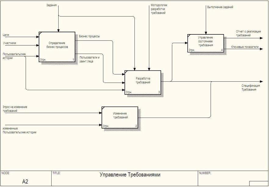
Fig. 6.7 - Domain Requirements Specification Management Scheme
5. An example of the description of the function “Task management”
Figure 6.8 shows a diagram representing the project's Job Management Domain (A4). Functionally, we have divided the domain into four processes:
- Formations of tasks based on the specifications of the requirements. Formation of tasks for the implementation of the requirements, including: design, development, testing, deployment, pilot implementation. This block should “cover” US08 User Stories.
- Formation of tasks for iteration. The assignment is controlled by the iteration plan. These requirements are taken from the standard project management process using an iterative approach.
- Formation of tasks at risk. The management of assignments for the risk mitigation plan is carried out.
- Accounting tasks. A report on the implementation of the task. There is a change in the status of project objects based on the results of tasks. This process should “cover” US09 User Stories.
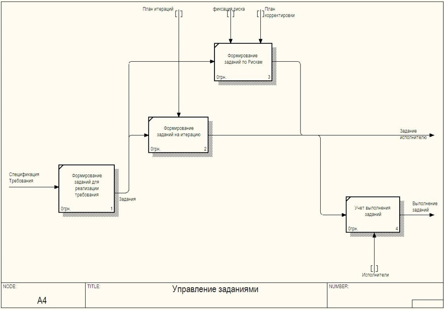
Fig. 6.8 - Project Task Management Domain Scheme
When modeling this domain, we have processes that we cannot match with any of the User stories. Therefore, we fill the gap. To do this, we must bring the problem to a joint discussion of the team with customers and form new User stories.
For process 5.2, we will describe the following User story:
US12. Based on the project iteration plan, select a pool of tasks that need to be implemented at this stage.
Objective: Get a list of tasks for implementation in the current iteration of the project.
Process 5.3 involves several User Stories:
US13 Prepare the requirements that will need to be implemented, upon the occurrence of the projected risk.
Objective: To develop alternative solutions for realizing the needs of the customer, when problems arise.
In the event of a risk, a user history of US8 is performed.
6. Example of the description of the function “Execution control”
Figure 6.9 shows a diagram representing the project management domain of the project. The implementation of this domain is a bit beyond the scope of our project, but closely related to it. Therefore, consider it.
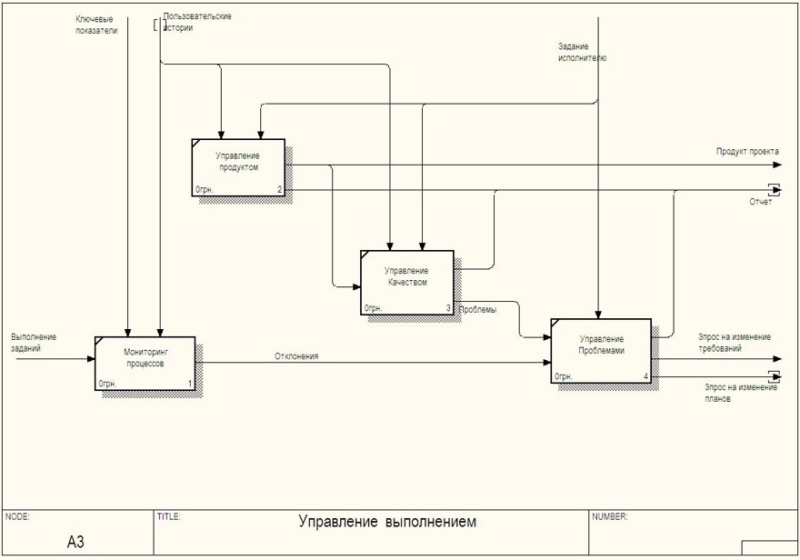
Fig. 6.9 - Domain Management Project Scheme
Functionally, we have divided the domain into four processes:
- Project product management. Fixed release of the product. Release reports are generated.
- Quality control. An analysis is made of the correction of the remarks of the previous review. The compliance of the Release with requirements is determined. A quality control report is issued. Identify new problems.
- Problem management. Responding to abnormalities during the execution of processes. Errors are prioritized, change requests are made.
- Monitoring and analysis of processes. The comparison of planned values of key indicators with real ones is performed. Defined deviation values. Indicators are monitored - triggers ("signs of risk", "symptoms of risk"), indicating that risk events have occurred or will occur in the near future. This process should “cover” US11 User stories.
7. Let's summarize the process of defining system functions and project boundaries.
Thus, in several passes, layer by layer, the functional model of the product being developed is refined and detailed and the boundaries of its contours are determined. As a result of this activity, we get a detailed process model that needs to be implemented. As can be seen from the diagrams, in addition to the list of automated functions, all information flows connecting them are also indicated.
Now, if we want to take a function beyond the scope of a project or its stage, we can analyze dependencies and avoid “sagging” other functions in the process line.
As a result, based on the diagrams developed by us, we can, at the first stage, move beyond the project the functions of the “A3 Implementation Management Group”, as well as the functions “A4.2 Formation of tasks for iteration” and “A4.3 Formation of tasks at risk occurrence”. The diagram shows that as a result, the system will lose data flow - “tasks for executors” caused by risk leveling.
Now, whenever the customer invites you to include new functionality in the product, you must first capture the changes in the Process diagram (functions), determine the extent of changes and their effects for the system as a whole.
In the next part, we will detail the processes included in the system reference
.
Bibliography
1. Jacobson A., Butch G., Rambo J. - “Unified Software Development Process” (2004)
2. David A. Mark and Clement McGowan - “SADT Structural Analysis and Design Methodology”
3. Coburn - "Modern methods for describing functional requirements" (2002)
4. Leffingwell Dean, Widrich Don - “Principles of working with software requirements” (2002)
5. Karl I. Wigers - “Developing Software Requirements” (2002)
6. Elizabeth Hull, Ken Jackson, Jeremy Dick - “Developing and Managing Requirements A Practical User Guide” (2005)
7. Scott Ambler - “Flexible Technologies: Extreme Programming and a Unified Development Process” (2005)
8. Greenfield Jack, Kane Short - "Software Development Factories" (2007)
9. Alistair Cowburn - “Each project has its own methodology”
10. Wolfson Boris - “Flexible development methodologies”
11. Leszek A. - “Requirements Analysis and System Design”
12. Freeman Eric, Freeman Elizabeth - “Design Patterns” (2011)
13. Evans Erik - “Subject-Oriented Design” (2011)
14. GOST 34.602-89 “Information technology. Set of standards for automated systems. Terms of Reference for the creation of an automated system "
Source: https://habr.com/ru/post/336950/
All Articles