Revit API Vector Geometry for Developers
The XYZ class represents coordinates in RevitAPI. And since we are dealing with coordinates, then we should consider the basics of vector geometry. Only two actions: addition and subtraction of vectors, will allow you to do a lot of useful work.
For a start, I suggest to get acquainted with the specification of the class XYZ here . What are vectors can be read in Wikipedia .
The XYZ class in RevitAPI in the model space can be represented as a vector, the beginning of which is at the zero point or base point of the project (X = 0, Y = 0, Z = 0), and the end of the vector is at the point that the coordinates indicate to us, for example XYZ (-44.6464513504241, 82.7973662674829, 33.0782338854701). All coordinate values are in feet. Class XYZ has methods inherent to the vectors, which will be discussed below.
')
Consider the vectors on the example of the line of detail in Revit. Mark the base point as A. Then the first point of the line (with which we started to lead it) will be B, the ending point of the line will be C. Accordingly, we will get the vectors AB and BC.
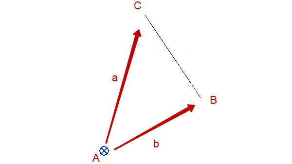
The Revit API provides methods for accessing the first point and the last point of the line.
Reference r = uiapp.ActiveUIDocument.Selection.PickObject(ObjectType.Element)
Element line = doc.GetElement(r.ElementId);
XYZ vectorAB = (line.Location as LocationCurve).Curve.GetEndPoint(0);
XYZ vectorAC = (line.Location as LocationCurve).Curve.GetEndPoint(1);
TaskDialog.Show("", vectorAB.ToString() + "\n" + vectorAC);
To work with the line of detail as a vector, we need the BC vector. To obtain the vector of the line of detail of the sun, we use the subtraction of the vectors.
SU = AS - AB
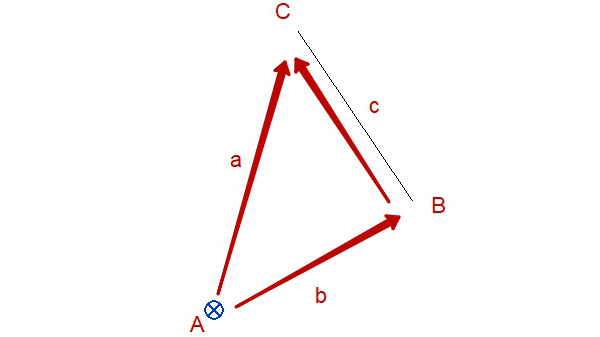
Everything is simple, in this expression the end of the AC vector will be the end of the BC vector (the first number in the difference is the end). The end of the vector AB will be the beginning of the BC vector (the second number in the difference is the beginning).
XYZ vectorBC = vectorAC - vectorAB;Now that you have a vector of detail, you can do a lot of interesting things. For example, you can build a copy of the line that will be twice as long or find the middle of the line of detail.
XYZ vectorBC_1 = vectorBC * (-2) // B
XYZ vectorBC_2 = vectorBC * 2; //
XYZ vectorBC_05 = vectorBC * .5 //
//
Line line = Line.CreateBound(vectorAB, vectorBC_2); // , XYZ -
doc.Create.NewDetailCurve(doc.ActiveView, line);
Next, consider the addition of vectors.
Adding vectors is very useful if you need to place an object at a certain distance from an already known point. To do this, you will need to use the coordinates of such a point and a normalized vector (or a unit vector). The normalized or unit vector is a vector whose length is equal to one. Read more here .
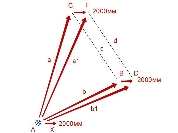
Construct a duplicate of a line horizontally to the right at a distance of 2000 mm from the existing one. To do this, I first display the graphically desired result. First we find the necessary coordinates by the parallelogram rule. The coordinates of the new line of detail is determined as follows:
AF = AC + AF; AD = AB + BD;
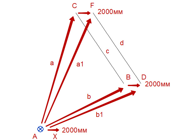
According to the parallelogram rule, instead of the vectors CF and BD we can use the vector AX, which is very simple to calculate. Let's use the normalized vector that the Revit API gives us - this is XYZ.BasisX. The length of this vector is equal to one, and it, like all basic vectors, is located at the origin of coordinates. Therefore, multiply it by 2000mm, remembering to convert millimeters to feet.
XYZ vectorAX = XYZ.BasisX * (2000 / 304.8);
// AF AD
XYZ vectorAF = vectorAC + vectorAX;
XYZ vectorAD = vectorAB + vectorAX;
Found vectors vectorAF and vectorAD are the exact coordinates for building a new line of detail.
Let's see how you can, for example, extend our line of detail by 1000 mm towards point C or B.
//
XYZ directionToC = vectorBC.Normalize();
XYZ newC = vectorAC + (directionToC * (1000 / 304.8));
//
XYZ vectorCB = vectorAB - vectorAC;
XYZ directionToB = vectorCB.Normalize();
XYZ newB = vectorAB + (directionToB * (1000 / 304.8));
A few words about the Normalize method of class XYZ. Normalize returns the normalized BC or CB vector. That is, this is a BC or CB vector, shortened to a length of 1 and placed at the origin with the direction preserved.
For an exciting journey through the three-dimensional world when developing programs for Revit, we need only a reference point with known coordinates and a motion pointer in the form of a normalized (single) vector , and distance . The product of the pointer with the distance , and the anchor point added to it will give the new coordinates. The project space in Revit is simply filled with pointers that can be obtained from many elements. We can calculate our pointers as in the example above.
For a comfortable journey through the three-dimensional world, we still need to arm ourselves with the knowledge of the normal to the straight line or to the surface and the scalar product of vectors . It is necessary to obtain information on the intersection of lines and, in Revit, which is popular in particular cases - the intersection of segments .
Below you can see the macro listing for Revit, which shifts the selected detail line by 2000mm to the right and extends it by 1000mm in both directions.
Show Macro for Revit C #
/*
;* Created by SharpDevelop.
* User: Akunets Aleksandr, www.bim3d.ru
* Date: 27.08.2017
* Time: 20:37
*
* To change this template use Tools | Options | Coding | Edit Standard Headers.
*/
using System;
using Autodesk.Revit.UI;
using Autodesk.Revit.DB;
using Autodesk.Revit.UI.Selection;
using System.Collections.Generic;
using System.Linq;

namespace Vector
{
[Autodesk.Revit.Attributes.Transaction(Autodesk.Revit.Attributes.TransactionMode.Manual)]
[Autodesk.Revit.DB.Macros.AddInId("17333FA7-9C10-4B4E-A179-7B56E33FC6B3")]
public partial class ThisApplication
{
private void Module_Startup(object sender, EventArgs e)
{

}

private void Module_Shutdown(object sender, EventArgs e)
{

}

public void Vector() {

UIDocument uidoc = this.ActiveUIDocument;

Document doc = uidoc.Document; //

Selection selection = uidoc.Selection;

Reference r = selection.PickObject(ObjectType.Element, " "); //

Element line = doc.GetElement(r.ElementId); //

XYZ vectorAB = (line.Location as LocationCurve).Curve.GetEndPoint(0); //

XYZ vectorAC = (line.Location as LocationCurve).Curve.GetEndPoint(1); //

XYZ vectorBC = vectorAC - vectorAB; // ,

XYZ vectorAX = XYZ.BasisX * (2000 / 304.8); // 2000 ( 2000 )

XYZ vectorAF = vectorAC + vectorAX; // ()

XYZ vectorAD = vectorAB + vectorAX; // ()

XYZ directionToC = vectorBC.Normalize(); // ( ) ,
//

XYZ newC = vectorAF + (directionToC * (1000 / 304.8)); // ()

//
XYZ vectorCB = vectorAB - vectorAC; // , BC

XYZ directionToB = vectorCB.Normalize(); // ( ) B,
//

XYZ newB = vectorAD + (directionToB * (1000 / 304.8)); // ()

Transaction t = new Transaction(doc, "Create Detail Line");
{
t.Start();

Line geomLine = Line.CreateBound(newB, newC);

DetailLine detailline = doc.Create.NewDetailCurve(doc.ActiveView, geomLine ) as DetailLine;

t.Commit();
}
}

#region Revit Macros generated code
private void InternalStartup()
{
this.Startup += new System.EventHandler(Module_Startup);
this.Shutdown += new System.EventHandler(Module_Shutdown);
}
#endregion
}
}
Source: https://habr.com/ru/post/336502/
All Articles