How to overcome common graphics artifacts
Artists drew bright graphics, programmers built it into the game, animators added movement - it would seem, everything is ready. But no, managers do not like:
You look at game resources - there’s nothing in them, all sprites are cut off. You read the code - the formulas are correct, the accuracy of the shader is enough. But the result was still unimportant. Where is the mistake?
')
A small survey for those who already know where the artifacts come from. What to do in this situation?
What answer option is correct, why exactly it and how to overcome graphics artifacts read under the cut.
On mobile platforms, bilinear texture filtering is used so that sprites can move smoothly and at different resolutions do not spread out to pixels. In terms of OpenGL ES, this is the GL_LINEAR parameter:

4x magnification example (center GL_NEAREST, right GL_LINEAR).

Example of a decrease of 2 times (center GL_NEAREST, right GL_LINEAR).

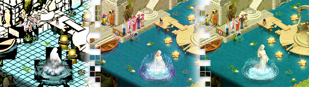
In the game, white artifacts are visible near tree branches, although there is nothing in the editor. According to the description, everything is like here.
When a texture is drawn with a scale other than 1.0 or with fractional coordinates, color artifacts appear on the border with transparency. The fact is that OpenGL ES for ordinary RGBA textures first independently interpolates the R, G, B, A channels, and only then this result is mixed with the screen. If for a channel with alpha (A) interpolation looks natural, then for color channels R, G, B, previously invisible pixels begin to affect the visible neighbors on the boundary of the object.
As one of the solutions to the problem, it is proposed to use textures with a pre-multiplied alpha ( premultiplied alpha ), then interpolation will occur without artifacts. It is the premultiplied alpha mode that is useful when drawing graphics to a target, in particular when self-implementing smoothing of 3D models using OpenGL ES 2.0.
An alternative solution is to add strokes in transparent areas. To do this, transparent pixels borrow a color from an opaque neighbor or average colors from several opaque neighbors. Such a calculation is conveniently carried out by the wave front from the transparent to opaque border.

Example of a 2-pixel stroke in a transparent area (far right)
In addition, you can collect graphic sets for all permissions and draw sprites only in whole coordinates. On retina-screens, the movement will be fairly smooth. Only here there will be a lot of graphics.
One has only to think about how the texture is drawn in non-integer coordinates on a unit scale, how the border aliasing problem immediately arises. The fact is that iron calculates physical pixels in the pixel shader, and for our fractional border, the texture coordinates s, t are shifted beyond [0..1]. In the GL_CLAMP_TO_EDGE mode , when the texture is overrun , the frame is duplicated. For textures that fit, this is normal, but for various sprites there are thickenings.
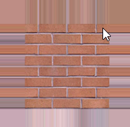
In order not to ruffle the edges of the sprite, it is enough to make a single-pixel (for scale 1) or 2-pixel (for scale 0.5) transparent frame and draw it as part of the sprite. In other words, the trim command in the graphical editor not only removes transparency, but also adds to the aliasing problem. Therefore, it would be more correct to trim, and after it to increase the canvas relative to the center by 2 pixels (normal graphics) or 4 pixels (retina graphics with the possibility of downscale).


An example of border aliasing (above) and smooth motion (below)
For 3D, by the way, the overdraw idea also works , but the implementation requires preliminary calculations and the formation of additional triangles with transparency.
When a texture is placed in an atlas, the GL_CLAMP_TO_EDGE mode property is lost, because now it works on the borders of the entire atlas. And since there is no duplication of boundaries for the elements of the atlas, then the joints may break.

Gaps in honey when putting textures into satin
Here, the duplication of the outer boundary of the joining elements in the atlas itself comes to the rescue. The size of the frame depends on the scale of rendering, usually 1-2 pixels are enough. With a scale> = 1, a single pixel frame is sufficient. Only in the case of reduction requires 2 or more pixels.
In order for the game to work on devices with a small amount of RAM, it is necessary to compress atlases in one of the available formats: PVRTC, ETC1, DXT1, DXT5, ETC2, etc.
The peculiarity of these hardware formats is the division of the whole texture into 4x4 blocks and further lossy compression. In addition to blockiness, no more than 2 basic colors are usually available for each block. As a result, all 16 pixels of a block are obtained by choosing from 4 possible values, calculated in some way based on the base colors.
For formats with independent blocks ( ETC1 / 2 , DXT1 / 5), it suffices to expand each element that fits in a regular atlas to a rectangle with a size of 4 pixels. In this case, the neighboring elements will not affect each other.

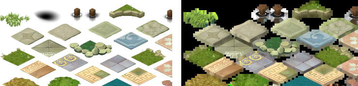
An example of the separation of elements of atlas in 4x4 blocks
For the PVRTC format, where colors of 4 adjacent blocks affect almost every pixel, it is necessary to dilute the elements of the atlas by a distance of 4 pixels. This is achieved by forming a 2-pixel protective area along the contour of each atlas element, and the useful area is centered in this case.
For polygonal atlases helps to maintain the distance between adjacent elements.
The considered methods are united by special processing of graphic data: both separate textures and elements of atlas. Such processing is well automated and, as a rule, does not distract employees from the creative process.
Therefore, in the survey the most general correct answer is 6, “It should have been like this, because we did not prepare graphic data.” I note that this does not detract from the usefulness of other methods.
Now is the time to think and ask: “What can a used resource collector do and is it provided for the preparation of graphic data by processes?”
PS Comments on the considered methods are welcome, as well as information on other effective ways of dealing with artifacts in 2D graphics.
“We need to remove gray spots and white lines. Here the pulsating button twitches, there the progress bar goes up the ladder. ”
You look at game resources - there’s nothing in them, all sprites are cut off. You read the code - the formulas are correct, the accuracy of the shader is enough. But the result was still unimportant. Where is the mistake?
')
A small survey for those who already know where the artifacts come from. What to do in this situation?
- Need a powerful graphics card and fresh drivers;
- It is worth making downloadable graphics sets for all possible screen resolutions;
- Square textures with a size of two do not have such problems;
- This is all due to the compression of graphics (PVRTC / DXT5 / ETC1 / ...);
- In a graphics editor, you'll have to slightly smudge the edges;
- It should have turned out this way, because we have not prepared graphic data;
- Only anti-aliasing will help;
- Looking for textures and targets in premultiplied alpha mode.
What answer option is correct, why exactly it and how to overcome graphics artifacts read under the cut.
Bilinear texture filtering
On mobile platforms, bilinear texture filtering is used so that sprites can move smoothly and at different resolutions do not spread out to pixels. In terms of OpenGL ES, this is the GL_LINEAR parameter:
glTexParameteri(GL_TEXTURE_2D, GL_TEXTURE_MIN_FILTER, GL_LINEAR); glTexParameteri(GL_TEXTURE_2D, GL_TEXTURE_MAG_FILTER, GL_LINEAR); 4x magnification example (center GL_NEAREST, right GL_LINEAR).
Example of a decrease of 2 times (center GL_NEAREST, right GL_LINEAR).
In the game, white artifacts are visible near tree branches, although there is nothing in the editor. According to the description, everything is like here.
When a texture is drawn with a scale other than 1.0 or with fractional coordinates, color artifacts appear on the border with transparency. The fact is that OpenGL ES for ordinary RGBA textures first independently interpolates the R, G, B, A channels, and only then this result is mixed with the screen. If for a channel with alpha (A) interpolation looks natural, then for color channels R, G, B, previously invisible pixels begin to affect the visible neighbors on the boundary of the object.
As one of the solutions to the problem, it is proposed to use textures with a pre-multiplied alpha ( premultiplied alpha ), then interpolation will occur without artifacts. It is the premultiplied alpha mode that is useful when drawing graphics to a target, in particular when self-implementing smoothing of 3D models using OpenGL ES 2.0.
An alternative solution is to add strokes in transparent areas. To do this, transparent pixels borrow a color from an opaque neighbor or average colors from several opaque neighbors. Such a calculation is conveniently carried out by the wave front from the transparent to opaque border.
Example of a 2-pixel stroke in a transparent area (far right)
In addition, you can collect graphic sets for all permissions and draw sprites only in whole coordinates. On retina-screens, the movement will be fairly smooth. Only here there will be a lot of graphics.
Pixel shaders
One has only to think about how the texture is drawn in non-integer coordinates on a unit scale, how the border aliasing problem immediately arises. The fact is that iron calculates physical pixels in the pixel shader, and for our fractional border, the texture coordinates s, t are shifted beyond [0..1]. In the GL_CLAMP_TO_EDGE mode , when the texture is overrun , the frame is duplicated. For textures that fit, this is normal, but for various sprites there are thickenings.
In order not to ruffle the edges of the sprite, it is enough to make a single-pixel (for scale 1) or 2-pixel (for scale 0.5) transparent frame and draw it as part of the sprite. In other words, the trim command in the graphical editor not only removes transparency, but also adds to the aliasing problem. Therefore, it would be more correct to trim, and after it to increase the canvas relative to the center by 2 pixels (normal graphics) or 4 pixels (retina graphics with the possibility of downscale).
An example of border aliasing (above) and smooth motion (below)
For 3D, by the way, the overdraw idea also works , but the implementation requires preliminary calculations and the formation of additional triangles with transparency.
Atlases
When a texture is placed in an atlas, the GL_CLAMP_TO_EDGE mode property is lost, because now it works on the borders of the entire atlas. And since there is no duplication of boundaries for the elements of the atlas, then the joints may break.
Gaps in honey when putting textures into satin
Here, the duplication of the outer boundary of the joining elements in the atlas itself comes to the rescue. The size of the frame depends on the scale of rendering, usually 1-2 pixels are enough. With a scale> = 1, a single pixel frame is sufficient. Only in the case of reduction requires 2 or more pixels.
Compressed atlases
In order for the game to work on devices with a small amount of RAM, it is necessary to compress atlases in one of the available formats: PVRTC, ETC1, DXT1, DXT5, ETC2, etc.
The peculiarity of these hardware formats is the division of the whole texture into 4x4 blocks and further lossy compression. In addition to blockiness, no more than 2 basic colors are usually available for each block. As a result, all 16 pixels of a block are obtained by choosing from 4 possible values, calculated in some way based on the base colors.
For formats with independent blocks ( ETC1 / 2 , DXT1 / 5), it suffices to expand each element that fits in a regular atlas to a rectangle with a size of 4 pixels. In this case, the neighboring elements will not affect each other.
An example of the separation of elements of atlas in 4x4 blocks
For the PVRTC format, where colors of 4 adjacent blocks affect almost every pixel, it is necessary to dilute the elements of the atlas by a distance of 4 pixels. This is achieved by forming a 2-pixel protective area along the contour of each atlas element, and the useful area is centered in this case.
For polygonal atlases helps to maintain the distance between adjacent elements.
Results
The considered methods are united by special processing of graphic data: both separate textures and elements of atlas. Such processing is well automated and, as a rule, does not distract employees from the creative process.
Therefore, in the survey the most general correct answer is 6, “It should have been like this, because we did not prepare graphic data.” I note that this does not detract from the usefulness of other methods.
Now is the time to think and ask: “What can a used resource collector do and is it provided for the preparation of graphic data by processes?”
PS Comments on the considered methods are welcome, as well as information on other effective ways of dealing with artifacts in 2D graphics.
Source: https://habr.com/ru/post/336304/
All Articles