BIM: how we build builders in construction
According to our approximate estimate, based on 20 years of practice, you can “lose” up to 50-60% of the budget on earthworks. On reinforced concrete and finish exactly 30%. On re-order errors in case of collisions, the cost of an engineer increases by about 10%. It is for this simple reason that when an “evil customer” introduces a BIM model of a building, wild screams and groans begin on all sides.
BIM-control will now be on all government orders under the new standard, so the cries and groans will be especially epic.
Here I see a trace of all systems, I can get an accurate estimate for each node: and when I move or add an object, I will receive updates at once in all design and working documents.
')
What is a BIM model? This is a three-dimensional model of the building, where all systems are joined and linked in one single plan. We put the socket in the room - in the general estimate, a new socket and the corresponding footage of the cable appeared immediately. The accuracy of such a model on materials - 2%. On paper, they usually take a stock of 15%, and the excess of this stock is desperately “lost”.
Let's show examples better than I will tell.


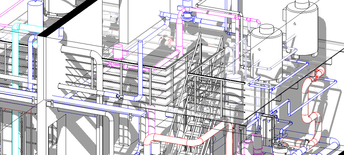
Here is the main view: here you can see the model of the building without rendering, just at the level of engineering schemes. In the window now open in the center there is a building for inspection, cuts on specific systems are visible in the background.

Here so all engineering systems of the building "in assembly" look.

You can disable the consistent view and see only specific subsystems. For example, this one - water supply.

And this is an electrician.

You can twist and increase the area of interest.

Switch to a different system view.

View individual nodes as "bricks", that is, objects (then it is convenient to duplicate them in the constructor, for example).


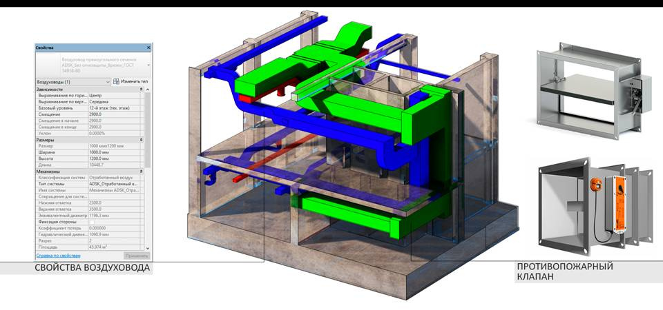
You can see the concrete structures and their properties.

Here is closer.

And already on them to impose types of systems or individual nodes.

For the customer, we usually collect a beautiful render (like below), and we use the view as above when designing.


About three years ago, computers began to pull BIM models of buildings. Of course, 3D buildings were designed in the Soviet Union, but now it has become truly accessible and easily reproducible.

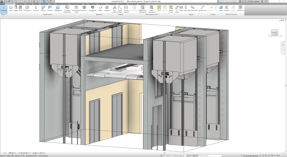
Even these “bricks”, that is, models of units, such as the device of elevators, are made in 3D and can be viewed from all sides. Since this is not “The Witcher” and not “Mass Effect”, the last thing they do is to optimize the engine, there is no special pre-preder, and powerful enough machines were needed for comfortable work with the system.
Today, building design can go in three ways:
For our office, the cutting of which is visible above, we used both methods. More precisely, they imported old 3-dimensional models and data on project documentation, and then began to support everything in BIM.
The first stage took several months from two specialists. We took the drawings from AutoCAD and imported them into the BIM environment. Something was in PDF, they had to be outlined by hand. We did the architecture and constructive month. The rest of the time - an engineer, in particular, had to go to the building, look at the places and photos. The most important thing that the scheme gave was the absence of system collisions. BIM-environment does not allow to cross the engineering subsystems: this is similar to the trace of the board. There are many ways to avoid this and catch bugs.
This is extremely important for the general contractor, because for each such collision at the facility he pays out of his sweat. I built a residential complex, built a skyscraper, in our team there is a person who has designed three metro stations from scratch, data centers and other smaller facilities - without an account at all. So, every damn time, when there is no BIM, the ventilation always comes to the column. We fix, move, change. Then the designer says: “It's not like that.” And the gimp starts from the beginning. Now we are designing right away in BIM, and this removes a lot of headaches.
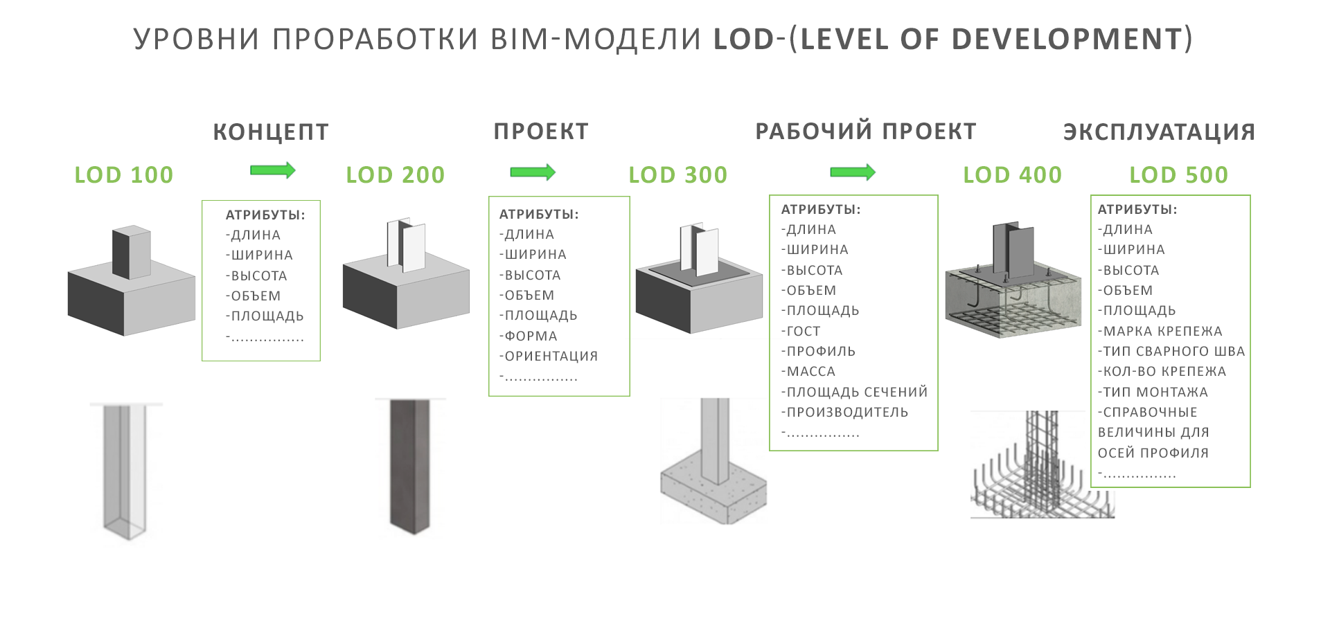
But back to our building. After all the systems were outlined, they began to saturate the engineer and arrange the drawings correctly so that BIM has full specifications. That is, at first, for example, the switchboard was just one node, such as a material point, then there appeared a division into separate large devices and lines inside, and then it became so detailed that we already knew the serial numbers of the parts. This depth of design is called LOD: the British standard for the levels of detail of information model elements. LOD100 and LOD200 are like in computer games, when there is a certain constructor and nodes. The model can be used for analysis (based on volumes, areas and orientations by applying generalized performance criteria) and estimating value based on calculated areas and volumes. Well, planning, of course. LOD300 is already a normal specification for the release of traditional design documentation and for carrying out various engineering calculations. There can also be considered equipment, products and materials, as well as rough work. The three hundredth model can be used to analyze collisions. LOD 400 is already a release of working documentation for carrying out various engineering calculations, for obtaining accurate data on equipment, products and materials for calculating the amount of work. This model can be used at the CMP stage, that is, will serve as a direct instruction to the builders. For each joint, you can safely ask. Lost cable meter - no one will notice. Missing 50 meters - immediately slept. We usually work at this level, but for our office we are threatening the LOD 500. This model can be used at the operational stage, where consumables like lamps and their life are visible.
The 400th LOD in construction practice gives several more obvious advantages. Here is one example. A very common mistake is an incorrect power calculation. This is usually done manually by comparing different plans. In BIM, it is automatically considered a system, and everything fits in as it should. Often, designers consider it according to different methodologies, or they simply do not notice any detail, and the equipment simply does not turn on in terms of power.
Exit for the budget is usually up to 7% for re-ordering new units (it’s still if you don’t have to change something in the layout on the fly to supply new equipment).
At the 500th LOD, the technical and economic indicators of the building are already one to one: it is also built with all the formulas for calculating loads, power, toilet bowls, openings and the exact amount of wire.
Further, having such a model, any automation modules are screwed to it. You can hang over the work schedule and watch. We will hang up automation in our building and give up part of the access to the control room in order to manage the building in Hollywood.
It is very convenient for estimators to work with BIM-model from the 400th LOD. Designers are comfortable - they quickly print and cut into knots. This greatly reduces the time of various jobs. Educated BIM superintendents twist and twist. Contractors at the construction site itself, of course, do not need this at all, all the “losses” are visible, and it is very difficult to falsify the documentation. The whole technical economy is checked: the earth mass is perfect, all the pipes, everything. Logs are written: who climbed into the model, when he climbed up, that looked, what changed. Naturally, all these modules complicate the work in terms of training (you need at least a month course at least to just read BIM professionally), but this is a requirement of standards. At the state competition now everything will be through the BIM-model. Uneducated contractors will suffer.
100 thousand square meters under the LOD 400 move costs about as much as 5-6 apartments in the center in money and a few months in operation. Oddly enough, it still pays well for the savings on the project. However, a more correct approach is to design it immediately in a BIM environment. This is longer for a month at the preparation stage, but it turns out almost free of charge in the total budget.
More expensive automation. For example, our colleagues made a module for a stadium control system; there are control sensors at the lower levels that check vibrations, the slope of walls and beams, and evaluate the appearance of defects in the metal. Simply put, it helps to understand that the stadium could collapse in six months or a year during normal life or in a few hours if it was damaged by an earthquake (but, it seems, it is worth it). The same data is transmitted to the MES in real time.
This is who needs it:

BIM-control will now be on all government orders under the new standard, so the cries and groans will be especially epic.
Here I see a trace of all systems, I can get an accurate estimate for each node: and when I move or add an object, I will receive updates at once in all design and working documents.
')
What is a BIM model? This is a three-dimensional model of the building, where all systems are joined and linked in one single plan. We put the socket in the room - in the general estimate, a new socket and the corresponding footage of the cable appeared immediately. The accuracy of such a model on materials - 2%. On paper, they usually take a stock of 15%, and the excess of this stock is desperately “lost”.
Let's show examples better than I will tell.
Here is the main view: here you can see the model of the building without rendering, just at the level of engineering schemes. In the window now open in the center there is a building for inspection, cuts on specific systems are visible in the background.
Here so all engineering systems of the building "in assembly" look.
You can disable the consistent view and see only specific subsystems. For example, this one - water supply.
And this is an electrician.
You can twist and increase the area of interest.
Switch to a different system view.
View individual nodes as "bricks", that is, objects (then it is convenient to duplicate them in the constructor, for example).
You can see the concrete structures and their properties.
Here is closer.
And already on them to impose types of systems or individual nodes.
For the customer, we usually collect a beautiful render (like below), and we use the view as above when designing.
About three years ago, computers began to pull BIM models of buildings. Of course, 3D buildings were designed in the Soviet Union, but now it has become truly accessible and easily reproducible.
Even these “bricks”, that is, models of units, such as the device of elevators, are made in 3D and can be viewed from all sides. Since this is not “The Witcher” and not “Mass Effect”, the last thing they do is to optimize the engine, there is no special pre-preder, and powerful enough machines were needed for comfortable work with the system.
How data is collected in such a model
Today, building design can go in three ways:
- In the old manner, that is, on paper, more precisely - in one of the CAD-systems. There will be a bunch of different documents, which later in the engineer’s mind are combined into one common project. This is a completely normal method when skilled professionals are involved in the work. But in reality, in the real world, anyway, someone will cross the cable channel and ventilation, if not in the design, then certainly in the implementation. Playing on the tolerances, the difference schemes and the absence of a single plan, you can quite a lot "lose".
- Start in the old fashioned way and get a sketch agreement in the old fashioned way, and then go to BIM and design everything right away. The intermediate stage is most often needed when the general contractor decides to control the construction normally.
- Design immediately in BIM. Then a sketch is one of the representations (just saving the model in a certain format and printing), the electricians' plan is a different representation, and so on. All this can even be coordinated in Moscow in electronic form.
For our office, the cutting of which is visible above, we used both methods. More precisely, they imported old 3-dimensional models and data on project documentation, and then began to support everything in BIM.
The first stage took several months from two specialists. We took the drawings from AutoCAD and imported them into the BIM environment. Something was in PDF, they had to be outlined by hand. We did the architecture and constructive month. The rest of the time - an engineer, in particular, had to go to the building, look at the places and photos. The most important thing that the scheme gave was the absence of system collisions. BIM-environment does not allow to cross the engineering subsystems: this is similar to the trace of the board. There are many ways to avoid this and catch bugs.
This is extremely important for the general contractor, because for each such collision at the facility he pays out of his sweat. I built a residential complex, built a skyscraper, in our team there is a person who has designed three metro stations from scratch, data centers and other smaller facilities - without an account at all. So, every damn time, when there is no BIM, the ventilation always comes to the column. We fix, move, change. Then the designer says: “It's not like that.” And the gimp starts from the beginning. Now we are designing right away in BIM, and this removes a lot of headaches.
But back to our building. After all the systems were outlined, they began to saturate the engineer and arrange the drawings correctly so that BIM has full specifications. That is, at first, for example, the switchboard was just one node, such as a material point, then there appeared a division into separate large devices and lines inside, and then it became so detailed that we already knew the serial numbers of the parts. This depth of design is called LOD: the British standard for the levels of detail of information model elements. LOD100 and LOD200 are like in computer games, when there is a certain constructor and nodes. The model can be used for analysis (based on volumes, areas and orientations by applying generalized performance criteria) and estimating value based on calculated areas and volumes. Well, planning, of course. LOD300 is already a normal specification for the release of traditional design documentation and for carrying out various engineering calculations. There can also be considered equipment, products and materials, as well as rough work. The three hundredth model can be used to analyze collisions. LOD 400 is already a release of working documentation for carrying out various engineering calculations, for obtaining accurate data on equipment, products and materials for calculating the amount of work. This model can be used at the CMP stage, that is, will serve as a direct instruction to the builders. For each joint, you can safely ask. Lost cable meter - no one will notice. Missing 50 meters - immediately slept. We usually work at this level, but for our office we are threatening the LOD 500. This model can be used at the operational stage, where consumables like lamps and their life are visible.
The 400th LOD in construction practice gives several more obvious advantages. Here is one example. A very common mistake is an incorrect power calculation. This is usually done manually by comparing different plans. In BIM, it is automatically considered a system, and everything fits in as it should. Often, designers consider it according to different methodologies, or they simply do not notice any detail, and the equipment simply does not turn on in terms of power.
Exit for the budget is usually up to 7% for re-ordering new units (it’s still if you don’t have to change something in the layout on the fly to supply new equipment).
At the 500th LOD, the technical and economic indicators of the building are already one to one: it is also built with all the formulas for calculating loads, power, toilet bowls, openings and the exact amount of wire.
What's next
Further, having such a model, any automation modules are screwed to it. You can hang over the work schedule and watch. We will hang up automation in our building and give up part of the access to the control room in order to manage the building in Hollywood.
It is very convenient for estimators to work with BIM-model from the 400th LOD. Designers are comfortable - they quickly print and cut into knots. This greatly reduces the time of various jobs. Educated BIM superintendents twist and twist. Contractors at the construction site itself, of course, do not need this at all, all the “losses” are visible, and it is very difficult to falsify the documentation. The whole technical economy is checked: the earth mass is perfect, all the pipes, everything. Logs are written: who climbed into the model, when he climbed up, that looked, what changed. Naturally, all these modules complicate the work in terms of training (you need at least a month course at least to just read BIM professionally), but this is a requirement of standards. At the state competition now everything will be through the BIM-model. Uneducated contractors will suffer.
How much is it
100 thousand square meters under the LOD 400 move costs about as much as 5-6 apartments in the center in money and a few months in operation. Oddly enough, it still pays well for the savings on the project. However, a more correct approach is to design it immediately in a BIM environment. This is longer for a month at the preparation stage, but it turns out almost free of charge in the total budget.
More expensive automation. For example, our colleagues made a module for a stadium control system; there are control sensors at the lower levels that check vibrations, the slope of walls and beams, and evaluate the appearance of defects in the metal. Simply put, it helps to understand that the stadium could collapse in six months or a year during normal life or in a few hours if it was damaged by an earthquake (but, it seems, it is worth it). The same data is transmitted to the MES in real time.
This is who needs it:
Links
- Here's a marketing video gash about BIM using our model
- About LOD
- About what else can be done with BIM in automation
- My mail: RBelov@croc.ru. If you have a question not for comments or a request for an approximate cost of design, or for transferring CAD to BIM, I will answer with pleasure.
Source: https://habr.com/ru/post/335808/
All Articles