A few words about testing complex hardware systems
Hey. Today I want to talk to you about iron testing - with painful examples and photos from everyday practice. This harsh reality with soldering, debugging and burned chips is usually all ruthlessly lacquered, telling only about successes - people responsible for PR and marketing are usually afraid of any mention of mistakes and failures like fire. But engineers understand that complex complexes are not born immaculate right away, so we are not afraid to tell you about testing as it is. Well, to share experiences, what to do and what to avoid.
- Everyone please observe the fastener belt and no smoking signs have been turned on. Sit back and enjoy your ride.
')
So, in order.
Testing is carried out at all stages of the life of the equipment. Testing happens initial (bringup), component, functional, load, production, and even testing at customers.
At the development stage of the equipment, the engineer thinks about how he will revive his brainchild. Boards are sprinkled with test points, debug connectors, jumpers, spare parts for spare parts and the like. The set of testing capabilities incorporated into the hardware is called DFT (Design for Testability). A board released in the DFT phase may contain twice as many components as a board that has been released in circulation. Naturally, following the principle of “work - do not touch”, then no one redoes it, and the end consumer puzzledly examines empty seats on the motherboard from the store, inventing various conspiracy theories about their purpose.

So, our board was taken from the factory - what to do next? Well, of course - plug into the outlet and release all white smoke from it.

- Everybody falls the first time.
A photo from the Internet, we did not find any burned boards, but I confess - sometimes this is done. In my memory there is an old story when a curious system architect sat and selected at random which connectors needed to plug a phase, neutral and earth (well, he didn’t have time to look into the scheme), and the developer sat next to him and caught the pale.
But usually everything happens differently. The first phase of testing - bringup (popularly "revive").
- Wake up, Neo ...
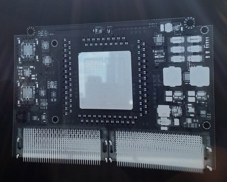
For bringup, usually 3-5 samples are made (in the hope that at least two will be destroyed in the delirium delirium). If the device contains expensive chips, they are not installed on one of the samples. Fab can offer you to save on gold - DO NOT AGREE TO ANY KIND (or you just have to solder a lot and often).

A motherboard without a chip is the first candidate for slaughter. It checks the power-on sequence, faults, voltage ratings and so on. Then this fee is an organ donor and / or a testing ground for testing all hypotheses. Also, before you include something, you must:
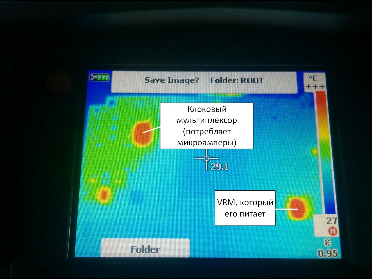
We played enough with the first victim - go to let the smoke out of combat pay. At the same time, you need to stock up on a pilot with a power cut-off button and a thermal imager. The pilot must be put under his foot, in case his hands beat 220 V (well, or just his hands are busy), and in the thermal imager you can see a short circuit.
But in general, when you first turn on, you can usually not be afraid - it most likely will not turn on, since you probably forgot to rewire components that have legs in the design:

And solder a little wire:

Hot-melt glue is our everything, the best friend of the developer, almost like a scotch in ordinary life.
Immediately after Dremel:

And the hammer, which has to hammer in the board, doesn't always come out neatly.


Sometimes you have to do a patient x-ray or tomography. It looks like this:
Scanning the film, it turns out, is not very easy. They took the phone on the ground opposite the window.
Specifically, in this picture you can not see anything - do not peer. But in general, on the X-ray, you can see the insolation, cracks and so on.
Separately it is necessary to say about bring up motherboards, because it is done differently. DFT samples of mothers are usually ordered a lot - about 20 pieces. It is expensive, so there is a strategy here.
Developers are taken and sent to the factory. About 5 boards gather and the conveyor stops. Next, the developers have about 30 minutes to enable the board (for x86 systems, the success criteria is to load the BIOS). If everyone is lucky, other samples are collected. If not, production is canceled, and the developers are going home to think. The money spent on the PCB is lost, but the components are waiting at the warehouse for the next attempt.
Good - we launched our board, and even launched others that should work with it. What's next? We collect the stand.
And then you probably expect to see this?

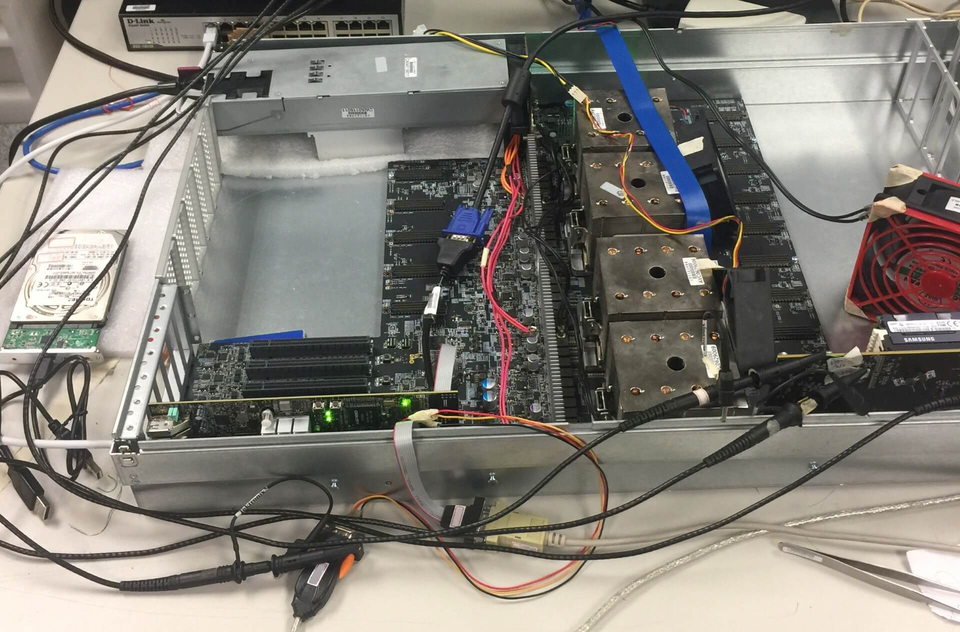
This is all window dressing for deputy ministers. This stand should be assembled from sticks and acorns, and looks like this:

- I didn't say it would be easy, Neo. I just said it would be the truth.
(a glass for a counterweight, a felt-tip pen - so that the radiator is sitting on it - it is wound there with a wire)
Or so:

This horde is stuffed into the laboratory:

And everyone starts to race to sew up their firmware, programs, and poke everywhere with an oscilloscope.
Sometimes in the process, the polite request “Dear colleague, please remove the soldering iron from my hand - it’s very hot” or “Be so kind - no longer turn on the power supply when I screw the board to the chassis”.
As our website says:

In our particular case, the main purpose of verifying the joint operation of several devices is to find out whether PCI Express is working, whether it meets the standard. Just without everything else, in principle, you can live. Usually the functionality laid in the piece of hardware is redundant. Tons of GPIO pins, I2C / SPI tires, thermal sensors, ice and other things, as a rule, remain unclaimed, as they are postponed for debugging at the last moment, which never occurs.
Naturally, we don’t have measuring instruments for every million rubles for each case - this is for the weak. We are in a hurry to help test software from manufacturers of components. Almost all modern chips with high-speed interfaces have a digital oscilloscope inside. To him relies specialized software that allows you to read his testimony. Run and watch eye diagrams. We see this:

Sometimes we see a dangerous squint:

And sometimes we catch squid:

Squids are the most dangerous. These are nonlinear distortions, and the built-in equalizers do not know how to deal with this. Squids mean that somewhere in the communication channel there is something very bad - a too long vias, a significant impedance drop, some unevenness in 1/4 or 1/2 wavelength of some harmonics in the useful band, etc. like that
Someone may notice that the squid is a bit like what it does with the received DFE signal in the PCIe receiver's equalizer. But in this case it’s still a squid, and not the result of the DFE work (just the result of the DFE work, the software we use cannot display).
Separately, I must say about the test software, which is also extremely insidious. For example, to remove eye diagrams, we use two versions of the same program - one version draws pictures, but does not write the meaning of opening the eyes, the second - vice versa.
Well, yes - if you plan to shoot your eyes on the I2C interface - forget it will be very, very slow. Only in-band. The problem is that for in-band removal your device should have a working PCIe link with the computer where the test software works, which is quite problematic when your piece of hardware is not installed in a standard PCIe slot. And the funny thing is that you should already have at least a working link on the channel that you are debugging, and it is in the mode (gen2 / 3) in which you need (for different eyes have different eyes and equalizers work in different ways) ). Nolegs, no link cartoons , no eyes - this is how you want, and get out.

About how to get out of a PCIe - I previously wrote a separate article .
In general, when developing a server, of course, support from the manufacturers of the components used is very important, since today the complexity of even relatively simple chips is such that it is unlikely to fully test and debug the system without using the test products built into them. Clock generators, voltage regulators, network controllers, PCI Express switches, redrivers - all this has built-in tools for tuning, diagnostics, and needs a certain set of programs and cables for connecting for full configuration and testing, without the use of which development becomes simply impossible.
In the process of conducting inspections, it sometimes turns out that somewhere something goes wrong. And then begins the fascinating process of localizing the error so that it can be fixed in the next revision. And it’s good if this “not so” is consistently repeated - then it is usually not difficult to find out exactly what is the cause of the error. But sometimes things are much worse. For example, on some copies of the boards during a long run of tests, there are single uncorrectable errors on the bus (which should not be completely). And here it is often necessary to apply the “gaze” method — that is, just to sit, hypothetically looking at the scheme, to assume what exactly might be the cause, try to eliminate this hypothetical reason in the scheme, and test it to verify whether we guessed or not.
We encountered this a few years ago, when NVIDIA tests (yes, many manufacturers provide specific test suites that allow you to test things that are not programmatically accessible using standard utilities) gave rare single errors during long (24 hours or more) runs on some board instances. . Then the whole thing turned out to be an unsuccessful trace of the reference clock (100 MHz) - although before we arrived at this, a lot of things were checked, starting with the quality of the power and ending with eye diagrams along all lines.
And by the way, this is good. The biggest nightmare of the developer - when everything works right away. This means only one thing - a mine is buried somewhere, which will work after the shipment of 100,500 pieces of equipment to the customer. The fact is that in the process of searching for the cause of a global problem, several hypotheses are tested and, as a rule, many minor faults are identified that have nothing to do with the problem that has arisen. There is no big problem - you will not find small ones. Your customers will find them for you.
- All the words I do.
After completing the component tests, functional testing begins - testing the operability of the complex as a whole and the correct operation of all the embedded functions. This is usually done by QA. The scope for creativity here, of course, is very extensive, but in general, the main emphasis is placed on the correct operation of the system when playing standard usage scenarios. Here, the detected errors may already have both a hardware and a software nature, so it is first of all important to find out what caused the error. Often, the first assumptions can be deceptive, that is, obviously a hardware problem at first glance may be caused by incorrect operation of the firmware. A significant part of the functional testing is checking how the system handles a variety of errors that may occur during operation. Modern debugging tools allow artificially injecting errors into standard processor interfaces, because at the iron level many of them are specifically problematic to create (well, don’t tear off the memory chips on the fly or close the PCI Express bus lines).
And ... I did not say that functional testing does not mean an assembled system ready for battle. Here, too, everything is not going smoothly. At some point, it turned out that we didn’t have OcuLink cables of the required length, and the server had guts.

And for some reason, in such a configuration with a load test, everything began to overheat. We are still wondering why. Cables were heated, I guess.
- You're faster than this. Don't think you are, you know ...
At some point, in parallel with the functional testing, load testing begins - it is important to make sure that the server continues to function correctly in the limiting operating modes. Moreover, load tests are carried out both in relation to individual subsystems (disks, memory, processors, input-output), and on the entire system as a whole. As a rule, localized tests make it possible to load one specific module more strongly than can be done at maximum load on the entire system.
In addition, debugging tools from the manufacturer of the hardware platform (for example, Hardware Tests Executive from IBM) help here. Thus, it is possible to drive the processor into quite limiting modes, which are fundamentally unattainable when working with real applications. The main problems detected during load testing are overheating, power instability or overcurrent overload, errors during active work with input-output interfaces.
Also come to the aid benchmarks. Because when the real value of the benchmarks is very different from the predicted - then something went wrong. A good reason to go poke board chopstick.
At the testing stage, we mainly use microbench marks:
For processors, these are usually single-threaded loads, such as spec2006 (now speccpu2017 ), parsec , but in general there is a huge amount of them from linux assembly and compression ( lzma , gzip ) to matrix multiplication and fast Fourier transform calculation ( fftw ).
Nothing has changed for memory for many years: STREAM , RAMspeed SMP , lmbench .
For drives: fio , iozone .
If all functional and load tests pass successfully, there are still a number of things that need to be checked - stability over the entire temperature range, resistance to vibration, compatibility check with a specific set of standard components (memory, disks, PCI Express controllers).
PS: After we checked everything and were delighted with the functional tests of the first server revision, three servers suddenly collapsed in our laboratory. We started checking the power supply and on the 1.2V line (powering the PCIe processor bus), we saw this:

I focus your attention - one cell 500mV. Nominal 1.2 V. Resistor made a mistake in the compensation circuit of one of the VRM. It was with such nutrition that all load tests, benchmarks, fryers, and the like were successfully passed, and the design happily went to the second revision.
So, when the death screen suddenly appears on your cozy home computer of a well-known brand, you shouldn’t think that this is “buggy Windows”.
Preliminary preparation
- Everyone please observe the fastener belt and no smoking signs have been turned on. Sit back and enjoy your ride.
')
So, in order.
Testing is carried out at all stages of the life of the equipment. Testing happens initial (bringup), component, functional, load, production, and even testing at customers.
At the development stage of the equipment, the engineer thinks about how he will revive his brainchild. Boards are sprinkled with test points, debug connectors, jumpers, spare parts for spare parts and the like. The set of testing capabilities incorporated into the hardware is called DFT (Design for Testability). A board released in the DFT phase may contain twice as many components as a board that has been released in circulation. Naturally, following the principle of “work - do not touch”, then no one redoes it, and the end consumer puzzledly examines empty seats on the motherboard from the store, inventing various conspiracy theories about their purpose.
So, our board was taken from the factory - what to do next? Well, of course - plug into the outlet and release all white smoke from it.
- Everybody falls the first time.
A photo from the Internet, we did not find any burned boards, but I confess - sometimes this is done. In my memory there is an old story when a curious system architect sat and selected at random which connectors needed to plug a phase, neutral and earth (well, he didn’t have time to look into the scheme), and the developer sat next to him and caught the pale.
But usually everything happens differently. The first phase of testing - bringup (popularly "revive").
Reviving Birth
- Wake up, Neo ...
For bringup, usually 3-5 samples are made (in the hope that at least two will be destroyed in the delirium delirium). If the device contains expensive chips, they are not installed on one of the samples. Fab can offer you to save on gold - DO NOT AGREE TO ANY KIND (or you just have to solder a lot and often).
A motherboard without a chip is the first candidate for slaughter. It checks the power-on sequence, faults, voltage ratings and so on. Then this fee is an organ donor and / or a testing ground for testing all hypotheses. Also, before you include something, you must:
- ring the ground-food, there is often a short circuit;
- visually inspect the board - the polarity of the capacitors is easily confused, the chips are upside down, chips are present, you can easily find passive components that have been torn off;
- study separately - but didn’t you put on the board the components that you asked not to install (life hacking: do not make the black mask on the first samples - it doesn’t see if the chip resistors are installed or not).
We played enough with the first victim - go to let the smoke out of combat pay. At the same time, you need to stock up on a pilot with a power cut-off button and a thermal imager. The pilot must be put under his foot, in case his hands beat 220 V (well, or just his hands are busy), and in the thermal imager you can see a short circuit.
But in general, when you first turn on, you can usually not be afraid - it most likely will not turn on, since you probably forgot to rewire components that have legs in the design:
And solder a little wire:
Hot-melt glue is our everything, the best friend of the developer, almost like a scotch in ordinary life.
Immediately after Dremel:
And the hammer, which has to hammer in the board, doesn't always come out neatly.
Sometimes you have to do a patient x-ray or tomography. It looks like this:
Scanning the film, it turns out, is not very easy. They took the phone on the ground opposite the window.
Specifically, in this picture you can not see anything - do not peer. But in general, on the X-ray, you can see the insolation, cracks and so on.
Separately it is necessary to say about bring up motherboards, because it is done differently. DFT samples of mothers are usually ordered a lot - about 20 pieces. It is expensive, so there is a strategy here.
Developers are taken and sent to the factory. About 5 boards gather and the conveyor stops. Next, the developers have about 30 minutes to enable the board (for x86 systems, the success criteria is to load the BIOS). If everyone is lucky, other samples are collected. If not, production is canceled, and the developers are going home to think. The money spent on the PCB is lost, but the components are waiting at the warehouse for the next attempt.
Good - we launched our board, and even launched others that should work with it. What's next? We collect the stand.
And then you probably expect to see this?
This is all window dressing for deputy ministers. This stand should be assembled from sticks and acorns, and looks like this:
- I didn't say it would be easy, Neo. I just said it would be the truth.
(a glass for a counterweight, a felt-tip pen - so that the radiator is sitting on it - it is wound there with a wire)
Or so:
This horde is stuffed into the laboratory:
And everyone starts to race to sew up their firmware, programs, and poke everywhere with an oscilloscope.
Sometimes in the process, the polite request “Dear colleague, please remove the soldering iron from my hand - it’s very hot” or “Be so kind - no longer turn on the power supply when I screw the board to the chassis”.
As our website says:
In our particular case, the main purpose of verifying the joint operation of several devices is to find out whether PCI Express is working, whether it meets the standard. Just without everything else, in principle, you can live. Usually the functionality laid in the piece of hardware is redundant. Tons of GPIO pins, I2C / SPI tires, thermal sensors, ice and other things, as a rule, remain unclaimed, as they are postponed for debugging at the last moment, which never occurs.
Naturally, we don’t have measuring instruments for every million rubles for each case - this is for the weak. We are in a hurry to help test software from manufacturers of components. Almost all modern chips with high-speed interfaces have a digital oscilloscope inside. To him relies specialized software that allows you to read his testimony. Run and watch eye diagrams. We see this:
Sometimes we see a dangerous squint:
And sometimes we catch squid:
Squids are the most dangerous. These are nonlinear distortions, and the built-in equalizers do not know how to deal with this. Squids mean that somewhere in the communication channel there is something very bad - a too long vias, a significant impedance drop, some unevenness in 1/4 or 1/2 wavelength of some harmonics in the useful band, etc. like that
Someone may notice that the squid is a bit like what it does with the received DFE signal in the PCIe receiver's equalizer. But in this case it’s still a squid, and not the result of the DFE work (just the result of the DFE work, the software we use cannot display).
Separately, I must say about the test software, which is also extremely insidious. For example, to remove eye diagrams, we use two versions of the same program - one version draws pictures, but does not write the meaning of opening the eyes, the second - vice versa.
Well, yes - if you plan to shoot your eyes on the I2C interface - forget it will be very, very slow. Only in-band. The problem is that for in-band removal your device should have a working PCIe link with the computer where the test software works, which is quite problematic when your piece of hardware is not installed in a standard PCIe slot. And the funny thing is that you should already have at least a working link on the channel that you are debugging, and it is in the mode (gen2 / 3) in which you need (for different eyes have different eyes and equalizers work in different ways) ). No
About how to get out of a PCIe - I previously wrote a separate article .
In general, when developing a server, of course, support from the manufacturers of the components used is very important, since today the complexity of even relatively simple chips is such that it is unlikely to fully test and debug the system without using the test products built into them. Clock generators, voltage regulators, network controllers, PCI Express switches, redrivers - all this has built-in tools for tuning, diagnostics, and needs a certain set of programs and cables for connecting for full configuration and testing, without the use of which development becomes simply impossible.
In the process of conducting inspections, it sometimes turns out that somewhere something goes wrong. And then begins the fascinating process of localizing the error so that it can be fixed in the next revision. And it’s good if this “not so” is consistently repeated - then it is usually not difficult to find out exactly what is the cause of the error. But sometimes things are much worse. For example, on some copies of the boards during a long run of tests, there are single uncorrectable errors on the bus (which should not be completely). And here it is often necessary to apply the “gaze” method — that is, just to sit, hypothetically looking at the scheme, to assume what exactly might be the cause, try to eliminate this hypothetical reason in the scheme, and test it to verify whether we guessed or not.
We encountered this a few years ago, when NVIDIA tests (yes, many manufacturers provide specific test suites that allow you to test things that are not programmatically accessible using standard utilities) gave rare single errors during long (24 hours or more) runs on some board instances. . Then the whole thing turned out to be an unsuccessful trace of the reference clock (100 MHz) - although before we arrived at this, a lot of things were checked, starting with the quality of the power and ending with eye diagrams along all lines.
And by the way, this is good. The biggest nightmare of the developer - when everything works right away. This means only one thing - a mine is buried somewhere, which will work after the shipment of 100,500 pieces of equipment to the customer. The fact is that in the process of searching for the cause of a global problem, several hypotheses are tested and, as a rule, many minor faults are identified that have nothing to do with the problem that has arisen. There is no big problem - you will not find small ones. Your customers will find them for you.
Check list
- All the words I do.
After completing the component tests, functional testing begins - testing the operability of the complex as a whole and the correct operation of all the embedded functions. This is usually done by QA. The scope for creativity here, of course, is very extensive, but in general, the main emphasis is placed on the correct operation of the system when playing standard usage scenarios. Here, the detected errors may already have both a hardware and a software nature, so it is first of all important to find out what caused the error. Often, the first assumptions can be deceptive, that is, obviously a hardware problem at first glance may be caused by incorrect operation of the firmware. A significant part of the functional testing is checking how the system handles a variety of errors that may occur during operation. Modern debugging tools allow artificially injecting errors into standard processor interfaces, because at the iron level many of them are specifically problematic to create (well, don’t tear off the memory chips on the fly or close the PCI Express bus lines).
And ... I did not say that functional testing does not mean an assembled system ready for battle. Here, too, everything is not going smoothly. At some point, it turned out that we didn’t have OcuLink cables of the required length, and the server had guts.
And for some reason, in such a configuration with a load test, everything began to overheat. We are still wondering why. Cables were heated, I guess.
And you can carry two watermelons in each hand?
- You're faster than this. Don't think you are, you know ...
At some point, in parallel with the functional testing, load testing begins - it is important to make sure that the server continues to function correctly in the limiting operating modes. Moreover, load tests are carried out both in relation to individual subsystems (disks, memory, processors, input-output), and on the entire system as a whole. As a rule, localized tests make it possible to load one specific module more strongly than can be done at maximum load on the entire system.
In addition, debugging tools from the manufacturer of the hardware platform (for example, Hardware Tests Executive from IBM) help here. Thus, it is possible to drive the processor into quite limiting modes, which are fundamentally unattainable when working with real applications. The main problems detected during load testing are overheating, power instability or overcurrent overload, errors during active work with input-output interfaces.
Also come to the aid benchmarks. Because when the real value of the benchmarks is very different from the predicted - then something went wrong. A good reason to go poke board chopstick.
At the testing stage, we mainly use microbench marks:
For processors, these are usually single-threaded loads, such as spec2006 (now speccpu2017 ), parsec , but in general there is a huge amount of them from linux assembly and compression ( lzma , gzip ) to matrix multiplication and fast Fourier transform calculation ( fftw ).
Nothing has changed for memory for many years: STREAM , RAMspeed SMP , lmbench .
For drives: fio , iozone .
If all functional and load tests pass successfully, there are still a number of things that need to be checked - stability over the entire temperature range, resistance to vibration, compatibility check with a specific set of standard components (memory, disks, PCI Express controllers).
PS: After we checked everything and were delighted with the functional tests of the first server revision, three servers suddenly collapsed in our laboratory. We started checking the power supply and on the 1.2V line (powering the PCIe processor bus), we saw this:
I focus your attention - one cell 500mV. Nominal 1.2 V. Resistor made a mistake in the compensation circuit of one of the VRM. It was with such nutrition that all load tests, benchmarks, fryers, and the like were successfully passed, and the design happily went to the second revision.
So, when the death screen suddenly appears on your cozy home computer of a well-known brand, you shouldn’t think that this is “buggy Windows”.
Source: https://habr.com/ru/post/335306/
All Articles