CDC + MSC USB Composite Device on STM32 HAL
I would like to believe that at least half of the readers can decipher at least half of the title of the article :) Who does not know - I will explain. My device should implement two USB functions at once:
- Mass Storage Device (aka Mass Storage Class - MSC ). I want my device to pretend to be a regular flash drive and give the files with the data that lie on the SD card.
- Another function is the virtual COM port (also known as USB Communication Class - CDC in USB terminology). Through this channel, I have any debugging output that is convenient to watch with an ordinary terminal.
In most examples of working with USB, only one type of device is implemented - a USB flash drive, a mouse, a custom HID device or a virtual COM port. But to find an imputed explanation of how to implement at least two functions at the same time was not so easy. In my article, I would like to fill this gap.
')
I will describe the creation of a composite USB device based on the STM32 microcontroller, but the approach itself will also be applicable to other microcontrollers. In the article I will examine in detail each of the classes separately, as well as the principle of building composite devices. But about everything in order.
So let's go!
Some theory
The USB interface is very complex, layered and multi-faceted. With a swoop it does not overpower. In one of the articles (I forgot, however, in what) I saw the phrase in the style “read this article 2 times, and then in the morning again”. Yes, he is, from the first time you will not master it. Personally, my interface more or less decayed on the shelves only after a couple of months of active digging and reading specifications.
I am still not an expert in USB, and therefore I would recommend to refer to articles that would describe the essence of what is happening in more detail. I will only point out the most important places and briefly explain how it works - for the most part I got into it myself. First of all, I would recommend Usb in a nutshell ( translation ), as well as USB Made Simple (I did not read it myself, but many recommend it). We also need specifications for specific classes of USB devices .
Probably the most important thing in the USB interface is the handle. More precisely, even the package descriptors. When a device connects to the bus, the host requests device descriptors that describe the device's capabilities, baud rates, polling frequency, which interfaces the device implements, and much more. The handle is an important and very gentle thing - even a mistake in one byte will result in the device not working.
The device describes itself with the help of several descriptors of different types:
- Device Descriptor - describes the device as a whole, its name, manufacturer, serial number. String data is described by separate string descriptors (String Descriptor)
- Configuration Descriptor — A device may have one or more configurations. Each configuration determines the speed of communication with the device, a set of interfaces and power settings. For example, a laptop that runs on battery can ask the device (choose a configuration) to use a lower exchange rate and switch to its own power source (instead of a laptop battery). Of course, this only works if the device provides this configuration.
- Interface descriptor - describes the interface for communicating with the device. Interfaces can be several. For example, different functions (MSC, CDC, HID) will implement their interfaces. Some functions (for example, CDC or DFU) implement several interfaces for their work at once. In our case, the composite device, we need to implement several interfaces from different functions at once and make them get along with each other.
- Endpoint descriptor - describes the communication channel within a specific interface, sets the packet size, describes the interrupt parameters. Using endpoints, we will receive and receive data.
- There are a bunch of different descriptors that describe specific aspects of specific interfaces.
The host requests the descriptors in a single byte stream. It is very important that within the same configuration descriptors go in a certain order, otherwise the host will get confused about which descriptor to what. Each configuration consists of a configuration descriptor and a set of descriptors describing interfaces. Each interface is described by an interface descriptor and a set of endpoint descriptors. Each entity carries its handles alongside.
You also need to understand that USB is a host oriented protocol. Device setup, reception, transfer - everything in USB is controlled from the host. For us, this means that there is no control flow from the microcontroller side - all USB work is based on interrupts and callbacks. And this, in turn, means that we don’t want to start long-running operations and need to be very careful when interacting with other interrupts (take into account priority, and so on). However, let's try not to go down to such a low level.
Also, host-centricity is also manifested in the name of the functions. In USB terminology, the direction from the host to the device is called OUT, although for the controller it is a trick. Conversely, the direction from the device to the host is called IN, although for us this means sending data. So in the microcontroller, the DataOut () function actually receives the data, and DataIn () sends the data. But this is so, by the way - we will use the already prepared code.
CDC - virtual COM port
Probably, taking the composite device at once will not work out entirely - too many nuances and pitfalls. I think it would be better to first debug each interface separately, and then go to the composite device. I'll start with the CDC, because It does not require any dependencies.
I recently moved to the STM32 Cube - a package of low-level drivers for the STM32. It has a USB control code with the implementation of individual classes of USB devices. Take the template implementation of USB Core and CDC and begin to cut for themselves. Blanks are in the \ Middlewares \ ST \ STM32_USB_Device_Library directory. I use Cube for STM32F1 series controllers , Cube version is 1.6 (April 2017), USB library version from the kit is 2.4.2 (December 2015)
Template implementation of the library involves writing your own code in files called template. Without an understanding of the entire library and the principles of USB operation, this is quite difficult to do. But we will go easier - we will generate these files using the CubeMX graphical configurator .
The implementation provided by CubeMX is ready to work right out of the box. Even a little offensive, that did not have to write any code. We'll have to study the CDC on the example of a completely finished implementation. Let's take a look at the most interesting places in the generated code.
First, let's look at the descriptors that are in the usbd_desc.c files (device descriptor) and usbd_cdc.c (configuration descriptors, interfaces, endpoints). The usb in a nutshell article ( in Russian ) has a very detailed description of all descriptors. I will not describe each field separately, I will dwell only on the most important and interesting fields.
Device handle
#define USBD_VID 1155 #define USBD_LANGID_STRING 1033 #define USBD_MANUFACTURER_STRING "STMicroelectronics" #define USBD_PID_FS 22336 #define USBD_PRODUCT_STRING_FS "STM32 Virtual ComPort" #define USBD_SERIALNUMBER_STRING_FS "00000000001A" #define USBD_CONFIGURATION_STRING_FS "CDC Config" #define USBD_INTERFACE_STRING_FS "CDC Interface" #define USBD_MAX_NUM_CONFIGURATION 1 /* USB Standard Device Descriptor */ __ALIGN_BEGIN uint8_t USBD_FS_DeviceDesc[USB_LEN_DEV_DESC] __ALIGN_END = { 0x12, /*bLength */ USB_DESC_TYPE_DEVICE, /*bDescriptorType*/ 0x00, /* bcdUSB */ 0x02, 0x02, /*bDeviceClass*/ 0x02, /*bDeviceSubClass*/ 0x00, /*bDeviceProtocol*/ USB_MAX_EP0_SIZE, /*bMaxPacketSize*/ LOBYTE(USBD_VID), /*idVendor*/ HIBYTE(USBD_VID), /*idVendor*/ LOBYTE(USBD_PID_FS), /*idVendor*/ HIBYTE(USBD_PID_FS), /*idVendor*/ 0x00, /*bcdDevice rel. 2.00*/ 0x02, USBD_IDX_MFC_STR, /*Index of manufacturer string*/ USBD_IDX_PRODUCT_STR, /*Index of product string*/ USBD_IDX_SERIAL_STR, /*Index of serial number string*/ USBD_MAX_NUM_CONFIGURATION /*bNumConfigurations*/ } ; /* USB_DeviceDescriptor */ Here we are interested in the following fields:
- bDeviceClass, bDeviceSubClass and bDeviceProtocol - describe to the host what kind of device it is, what it can do and which drivers to load. In this case, it says here that the device implements a Communication Device Class, which means that the host needs to make a virtual COM port and associate it with this device.
- PID (Product ID) and VID (Vendor ID) - according to these fields the host distinguishes between different devices connected to the system. The devices at the same time implement the same class. They say for devices sold on the market is very important to have a unique VID / PID, but I did not know who and where gives these ID-Schnick. For a home device in a single copy, the default values are sufficient.
Please note that string constants (device name, serial number) are not spelled out in the descriptor itself. Strings are described by separate descriptors, and all others only indicate the index of the string. In the case of the library from ST, the string handle is generated on the fly (grrrrrr), so I will not give it.
Configuration descriptor
__ALIGN_BEGIN const uint8_t USBD_CDC_CfgHSDesc[USB_CDC_CONFIG_DESC_SIZ] __ALIGN_END = { /*Configuration Descriptor*/ 0x09, /* bLength: Configuration Descriptor size */ USB_DESC_TYPE_CONFIGURATION, /* bDescriptorType: Configuration */ USB_CDC_CONFIG_DESC_SIZ, /* wTotalLength:no of returned bytes */ 0x00, 0x02, /* bNumInterfaces: 2 interface */ 0x01, /* bConfigurationValue: Configuration value */ 0x00, /* iConfiguration: Index of string descriptor describing the configuration */ 0xC0, /* bmAttributes: self powered */ 0x32, /* MaxPower 100 mA */ Here we are interested in the following:
- wTotalLength - the size of the entire packet of descriptors for this configuration - so that the host knows where this configuration ends and the next one begins. We will need to fix it when we make a composite device. Let me remind you that all interfaces for this configuration must be located in a solid block, and the value of wTotalLength determines the length of this block.
- bNumInterfaces: the Communication Device class is implemented using two interfaces. One for management, the other for the actual data to be sent.
- bmAttributes and MaxPower indicates that our device has its own power source, but wants to consume up to 100 mA from the USB port. These parameters will obviously have to be played in the future.
Next comes the handle to the first of the CDC interfaces. This class of devices can implement several different communication models (telephone, direct connection, multi-party connection), but in our case it will be the Abstract Control Model.
CDC Management Interface Descriptor
/*Interface Descriptor */ 0x09, /* bLength: Interface Descriptor size */ USB_DESC_TYPE_INTERFACE, /* bDescriptorType: Interface */ /* Interface descriptor type */ 0x00, /* bInterfaceNumber: Number of Interface */ 0x00, /* bAlternateSetting: Alternate setting */ 0x01, /* bNumEndpoints: One endpoints used */ 0x02, /* bInterfaceClass: Communication Interface Class */ 0x02, /* bInterfaceSubClass: Abstract Control Model */ 0x01, /* bInterfaceProtocol: Common AT commands */ 0x00, /* iInterface: */ Only one endpoint lives in this interface (bNumEndpoints). But first comes a series of functional descriptors - settings specific to this class of devices.
Functional descriptors
/*Header Functional Descriptor*/ 0x05, /* bLength: Endpoint Descriptor size */ 0x24, /* bDescriptorType: CS_INTERFACE */ 0x00, /* bDescriptorSubtype: Header Func Desc */ 0x10, /* bcdCDC: spec release number */ 0x01, /*Call Management Functional Descriptor*/ 0x05, /* bFunctionLength */ 0x24, /* bDescriptorType: CS_INTERFACE */ 0x01, /* bDescriptorSubtype: Call Management Func Desc */ 0x00, /* bmCapabilities: D0+D1 */ 0x01, /* bDataInterface: 1 */ /*ACM Functional Descriptor*/ 0x04, /* bFunctionLength */ 0x24, /* bDescriptorType: CS_INTERFACE */ 0x02, /* bDescriptorSubtype: Abstract Control Management desc */ 0x02, /* bmCapabilities */ /*Union Functional Descriptor*/ 0x05, /* bFunctionLength */ 0x24, /* bDescriptorType: CS_INTERFACE */ 0x06, /* bDescriptorSubtype: Union func desc */ 0x00, /* bMasterInterface: Communication class interface */ 0x01, /* bSlaveInterface0: Data Class Interface */ It says that our device does not know about the concept of "bell" (in the sense of a phone call), but it also understands the command line parameters (speed, stop bits, DTR / CTS bits). The last descriptor describes which of the two CDC interfaces is the manager, and where the data runs. In general, here we are not interested in anything and we will not change anything.
Finally, the endpoint handle for the control interface
/*Endpoint 2 Descriptor*/ 0x07, /* bLength: Endpoint Descriptor size */ USB_DESC_TYPE_ENDPOINT, /* bDescriptorType: Endpoint */ CDC_CMD_EP, /* bEndpointAddress */ 0x03, /* bmAttributes: Interrupt */ LOBYTE(CDC_CMD_PACKET_SIZE), /* wMaxPacketSize: */ HIBYTE(CDC_CMD_PACKET_SIZE), 0x10, /* bInterval: */ It says that this endpoint is used for interrupts. The host will poll the device once every 0x10 (16) ms with the question whether the device requires attention. Also, control commands will go through this end point.
The description of the second interface (where the data runs) will be simpler
CDC data interface and its endpoints
/*Data class interface descriptor*/ 0x09, /* bLength: Endpoint Descriptor size */ USB_DESC_TYPE_INTERFACE, /* bDescriptorType: */ 0x01, /* bInterfaceNumber: Number of Interface */ 0x00, /* bAlternateSetting: Alternate setting */ 0x02, /* bNumEndpoints: Two endpoints used */ 0x0A, /* bInterfaceClass: CDC */ 0x00, /* bInterfaceSubClass: */ 0x00, /* bInterfaceProtocol: */ 0x00, /* iInterface: */ /*Endpoint OUT Descriptor*/ 0x07, /* bLength: Endpoint Descriptor size */ USB_DESC_TYPE_ENDPOINT, /* bDescriptorType: Endpoint */ CDC_OUT_EP, /* bEndpointAddress */ 0x02, /* bmAttributes: Bulk */ LOBYTE(CDC_DATA_HS_MAX_PACKET_SIZE), /* wMaxPacketSize: */ HIBYTE(CDC_DATA_HS_MAX_PACKET_SIZE), 0x00, /* bInterval: ignore for Bulk transfer */ /*Endpoint IN Descriptor*/ 0x07, /* bLength: Endpoint Descriptor size */ USB_DESC_TYPE_ENDPOINT, /* bDescriptorType: Endpoint */ CDC_IN_EP, /* bEndpointAddress */ 0x02, /* bmAttributes: Bulk */ LOBYTE(CDC_DATA_HS_MAX_PACKET_SIZE), /* wMaxPacketSize: */ HIBYTE(CDC_DATA_HS_MAX_PACKET_SIZE), 0x00 /* bInterval: ignore for Bulk transfer */ In the interface, there are 2 end points of the bulk type - one to receive, the second to transfer. In fact, in USB terminology, this is one endpoint, just two-way.
I won’t explain how it all works, if only because I don’t understand it completely (for example, how the host knows how much data needs to be collected from the device). Most importantly, the library implements everything for us. Let's take a look at the architecture.
ST's USB library is quite layered. I would highlight such architectural levels.
- Class Driver (in the case of CDC, these are usbd_cdc and usbd_cdc_if files): implement the logic of a specific class of devices - CDC for virtual COM port, MSC for storage devices, HID for keyboards / mice and any specific devices with user interface.
- USB Core (usbd_core.c, usbd_ctlreq.c, usbd_ioreq.c): implements the general logic of all classes of USB devices, can give the requested handles to the host, processes requests from the host and configures the USB device as a whole. It also redirects data streams from a class driver to lower layers and vice versa.
- USB HW Driver (usbd_conf.c): The overlying layers are platform independent and work in the same way for several series of microcontrollers. The code does not have low-level function calls for a particular microcontroller. The usbd_conf.c file implements a layer between USB Core and HAL - a library of low-level drivers for the selected microcontroller. Basically, simple live wrappers live here, which redirect calls from top to bottom and callbacks from bottom to top.
- HAL (stm32f1xx_hal_pcd.c, stm32f1xx_ll_usb.c): communicate with the microcontroller's iron, handles registers and responds to interrupts.
At this stage, we will be interested only in the topmost layer and one function from usbd_conf.c. Let's start with the last one:
USBD_LL_Init () function
/** * @brief Initializes the Low Level portion of the Device driver. * @param pdev: Device handle * @retval USBD Status */ USBD_StatusTypeDef USBD_LL_Init (USBD_HandleTypeDef *pdev) { /* Init USB_IP */ /* Link The driver to the stack */ hpcd_USB_FS.pData = pdev; pdev->pData = &hpcd_USB_FS; hpcd_USB_FS.Instance = USB; hpcd_USB_FS.Init.dev_endpoints = 8; hpcd_USB_FS.Init.speed = PCD_SPEED_FULL; hpcd_USB_FS.Init.ep0_mps = DEP0CTL_MPS_8; hpcd_USB_FS.Init.low_power_enable = DISABLE; hpcd_USB_FS.Init.lpm_enable = DISABLE; hpcd_USB_FS.Init.battery_charging_enable = DISABLE; if (HAL_PCD_Init(&hpcd_USB_FS) != HAL_OK) { Error_Handler(); } HAL_PCDEx_PMAConfig((PCD_HandleTypeDef*)pdev->pData , 0x00 , PCD_SNG_BUF, 0x18); HAL_PCDEx_PMAConfig((PCD_HandleTypeDef*)pdev->pData , 0x80 , PCD_SNG_BUF, 0x58); HAL_PCDEx_PMAConfig((PCD_HandleTypeDef*)pdev->pData , 0x81 , PCD_SNG_BUF, 0xC0); HAL_PCDEx_PMAConfig((PCD_HandleTypeDef*)pdev->pData , 0x01 , PCD_SNG_BUF, 0x110); HAL_PCDEx_PMAConfig((PCD_HandleTypeDef*)pdev->pData , 0x82 , PCD_SNG_BUF, 0x100); return USBD_OK; } This function initializes the microcontroller's USB peripherals. The most interesting thing here is the series of HAL_PCDEx_PMAConfig () function calls. The fact is that on board the microcontroller there is a whole 512 bytes of memory allocated specifically for USB buffers (this memory is called PMA - Packet Memory Area). But since the device does not know in advance how many endpoints will be and what their parameters will be, this memory is not allocated. Therefore, before working with USB memory must be distributed according to the selected parameters.
But what is strange is that only 2 endpoints were announced, and 5 calls. Where did the extra ones come from? In fact, there is no extra here. The fact is that each USB device must have one two-way endpoint through which the device is initialized and then managed. This end point is always number 0. This function is not initialized by the end points, but by the buffer. For the zero end point, 2 buffers are created - 0x00 to receive and 0x80 to transmit (the high-order bit indicates the direction of transmission, the lower ones indicate the end-point number). The remaining 3 calls describe the buffers for the end point 1 (receiving and transmitting data) and the end point 2 (receiving commands and sending status - this happens synchronously, so there is only one buffer)
The last parameter in each call indicates the offset of the endpoint buffer in the common buffer. On the forums I saw the questions “what is this magic constant 0x18 (the starting address of the first buffer)?”. I will discuss this issue in detail later. Now I can only say that the first 0x18 bytes of PMA memory is occupied by the buffer allocation table.
But these are all guts and other entrails. And what's outside?
The user code operates on the transmit and receive functions that are in the usbd_cdc_if.c file. So that the device could send data to the virtual COM port in the direction of the host, we were provided with the function CDC_Transmit_FS ()
CDC_Transmit_FS () function
/** * @brief CDC_Transmit_FS * Data send over USB IN endpoint are sent over CDC interface * through this function. * @note * * * @param Buf: Buffer of data to be send * @param Len: Number of data to be send (in bytes) * @retval Result of the operation: USBD_OK if all operations are OK else USBD_FAIL or USBD_BUSY */ uint8_t CDC_Transmit_FS(uint8_t* Buf, uint16_t Len) { uint8_t result = USBD_OK; USBD_CDC_HandleTypeDef *hcdc = (USBD_CDC_HandleTypeDef*)hUsbDeviceFS.pClassData; if (hcdc->TxState != 0){ return USBD_BUSY; } USBD_CDC_SetTxBuffer(&hUsbDeviceFS, Buf, Len); result = USBD_CDC_TransmitPacket(&hUsbDeviceFS); return result; } The reception is a bit more complicated: the USB core will pull the CDC_Receive_FS () function as it receives data. In this function, you need to add your code that will process the received data. Or call a callback that will handle the processing, like this:
CDC_Receive_FS () function
/** * @brief CDC_Receive_FS * Data received over USB OUT endpoint are sent over CDC interface * through this function. * * @note * This function will block any OUT packet reception on USB endpoint * untill exiting this function. If you exit this function before transfer * is complete on CDC interface (ie. using DMA controller) it will result * in receiving more data while previous ones are still not sent. * * @param Buf: Buffer of data to be received * @param Len: Number of data received (in bytes) * @retval Result of the operation: USBD_OK if all operations are OK else USBD_FAIL */ static int8_t CDC_Receive_FS (uint8_t* Buf, uint32_t *Len) { uint16_t len = *Len; CDCDataReceivedCallback(Buf, len); // Prepare for next reception USBD_CDC_ReceivePacket(&hUsbDeviceFS); return (USBD_OK); } I pay attention that these functions work with arrays of bytes without any structure. In my case, I needed to send strings. To make it convenient, I wrote an analogue of the printf function, which formatted the string and sent it to the port. To speed up, I was also puzzled by double buffering. Read more here in the “Double Buffered USB” and “Printf” sections.
Also in the same file are the functions of initializing / deinitializing the virtual COM port, as well as the function of changing the port parameters (speed, parity, stop bits, etc.). The default implementation does not limit itself to speed and that suits me. Initialization is just as good. Leave everything as it is.
The final barcode - it all starts
the code that runs it all
USBD_Init(&hUsbDeviceFS, &FS_Desc, DEVICE_FS); USBD_RegisterClass(&hUsbDeviceFS, &USBD_CDC); USBD_CDC_RegisterInterface(&hUsbDeviceFS, &USBD_Interface_fops_FS); USBD_Start(&hUsbDeviceFS); Here different levels of the driver are initialized. The last command enables USB interrupts. It is important to understand that all work with USB occurs on request from the host. In this case, an interrupt is called inside the driver, which in turn either processes the request itself, or delegates this to another code via a callback.
To make it all work you need a driver from the operating system. As a rule, this is a standard driver and the system can pick up the device without a special installation procedure. As far as I understand, my system already installed the Virtual COM Port driver from STM (supplied with ST Flash Utility) and my device picked up on its own. On Linux, it also started with a half-kick.
MSC - storage device
With the CDC driver everything was simple - the device, as a rule, is itself the final consumer of data (for example, receives commands from the host) or a generator (for example, sends sensor readings to the host).
With Mass Storage Class will be a bit more complicated. The MSC driver is just an interlayer between the host and the USB bus on the one hand, and the storage device on the other. This could be an SDIO card connected via SDIO, SPI Flash, maybe a RAM Drive, a disk drive, and maybe even a network drive. In general, in most cases, the storage device will be represented by a certain driver (usually non-trivial), which we will need to interface with the MSC implementation.
My device uses an SD card connected via SPI. To access the files on this map I use the SdFat library. It is also divided into several levels of abstraction:
- The user is provided with the File class, through which you can create / open files, read and write data. The client code is not steamed by interaction with the storage medium and the subtleties of the file system.
- The Volume class deals with the entire kitchen in servicing the file system, directory, clusters, FAT and such. Communication with the data carrier is delegated to the underlying levels.
- SD card driver - this component knows how to communicate with the card, which commands to send to it, and which ones to listen to answers. The library provides several types of drivers for SPI and SDIO-connected cards. Theoretically, you can substitute your driver, for example, for a RAM disk.
- Overlying layers of cross-platform, they do not know how exactly the data will be written to the card or read from it. This allows you to build a library for different platforms (like Arduino, and others). For a specific platform or microcontroller, you can write a driver that will implement data transfer through the necessary interface. By default, the library provides several drivers, incl. for Arduinov SPI, but I got confused and wrote my driver
with preference and poetesstransfer via DMA based on HAL. - Finally, the HAL provides work with the registers of a particular microcontroller.
In the case of USB Mass Storage, we will not work with files on a flash drive - the host will do all the work of interpreting the file system. The device will receive requests to read or write a specific data block. So we will be interested in levels from the driver card and below.
The implementation of the MSC requires a specific interface from the repository - to be able to read and write, give its size and status. Approximately the same features are provided by the SdFat library SD card driver interface. It remains only to write an adapter that will lead one interface to another.
With the direction of movement determined. Let's deal with the implementation. I again used the CubeMX configurator and generated the necessary files for the USB component. The study will begin, of course, with descriptors.
Device handle
* USB Standard Device Descriptor */ __ALIGN_BEGIN uint8_t USBD_FS_DeviceDesc[USB_LEN_DEV_DESC] __ALIGN_END = { 0x12, /*bLength */ USB_DESC_TYPE_DEVICE, /*bDescriptorType*/ 0x00, /* bcdUSB */ 0x02, 0x00, /*bDeviceClass*/ 0x00, /*bDeviceSubClass*/ 0x00, /*bDeviceProtocol*/ USB_MAX_EP0_SIZE, /*bMaxPacketSize*/ LOBYTE(USBD_VID), /*idVendor*/ HIBYTE(USBD_VID), /*idVendor*/ LOBYTE(USBD_PID_FS), /*idVendor*/ HIBYTE(USBD_PID_FS), /*idVendor*/ 0x00, /*bcdDevice rel. 2.00*/ 0x02, USBD_IDX_MFC_STR, /*Index of manufacturer string*/ USBD_IDX_PRODUCT_STR, /*Index of product string*/ USBD_IDX_SERIAL_STR, /*Index of serial number string*/ USBD_MAX_NUM_CONFIGURATION /*bNumConfigurations*/ } ; /* USB_DeviceDescriptor */ The device handle hasn't changed much. The difference is only in the fields defining the device class - now the device class as a whole is not set (zeros in bDeviceClass), but will be set at the interface level (this is a specification requirement).
Configuration descriptor
0x09, /* bLength: Configuation Descriptor size */ USB_DESC_TYPE_CONFIGURATION, /* bDescriptorType: Configuration */ USB_MSC_CONFIG_DESC_SIZ, 0x00, 0x01, /* bNumInterfaces: 1 interface */ 0x01, /* bConfigurationValue: */ 0x04, /* iConfiguration: */ 0xC0, /* bmAttributes: */ 0x32, /* MaxPower 100 mA */ Very similar to the similar descriptor from the CDC - the number of interfaces (1) and the bus power parameters (up to 100 mA) are determined
Interface descriptor
0x09, /* bLength: Interface Descriptor size */ 0x04, /* bDescriptorType: */ 0x00, /* bInterfaceNumber: Number of Interface */ 0x00, /* bAlternateSetting: Alternate setting */ 0x02, /* bNumEndpoints*/ 0x08, /* bInterfaceClass: MSC Class */ 0x06, /* bInterfaceSubClass : SCSI transparent*/ 0x50, /* nInterfaceProtocol */ 0x05, /* iInterface: */ The interface descriptor declares 2 endpoints (one for each side of the transfer). The descriptor also defines which subclass Mass Storage is Bulk Only Transport. I have not found an explanatory description of what this particular subclass is. I assume that this is a device that communicates only through two-way data transfer through 2 endpoints (whereas other models can also use interrupts). The protocol in this conversation is the SCSI commands.
Endpoint Descriptors
0x07, /*Endpoint descriptor length = 7*/ 0x05, /*Endpoint descriptor type */ MSC_EPIN_ADDR, /*Endpoint address (IN, address 1) */ 0x02, /*Bulk endpoint type */ LOBYTE(MSC_MAX_FS_PACKET), HIBYTE(MSC_MAX_FS_PACKET), 0x00, /*Polling interval in milliseconds */ 0x07, /*Endpoint descriptor length = 7 */ 0x05, /*Endpoint descriptor type */ MSC_EPOUT_ADDR, /*Endpoint address (OUT, address 1) */ 0x02, /*Bulk endpoint type */ LOBYTE(MSC_MAX_FS_PACKET), HIBYTE(MSC_MAX_FS_PACKET), 0x00 /*Polling interval in milliseconds*/ Here 2 end points of the Bulk type are defined - the USB interface does not guarantee speed over such end points, but it guarantees data delivery. The packet size is set to 64 bytes.
Since we are talking about endpoints, it is worth looking into the usbd_conf.c file where the corresponding PMA buffers are defined.
Configuring PMA Buffers
HAL_PCDEx_PMAConfig((PCD_HandleTypeDef*)pdev->pData , 0x00 , PCD_SNG_BUF, 0x18); HAL_PCDEx_PMAConfig((PCD_HandleTypeDef*)pdev->pData , 0x80 , PCD_SNG_BUF, 0x58); HAL_PCDEx_PMAConfig((PCD_HandleTypeDef*)pdev->pData , 0x81 , PCD_SNG_BUF, 0x98); HAL_PCDEx_PMAConfig((PCD_HandleTypeDef*)pdev->pData , 0x01 , PCD_SNG_BUF, 0xD8); Now look at the MSC from the other side. This USB class accepts read / write commands from the host and broadcasts their specialized interface, USBD_StorageTypeDef. We can only substitute its implementation.
Device interface
/** @defgroup USB_CORE_Exported_Types * @{ */ typedef struct _USBD_STORAGE { int8_t (* Init) (uint8_t lun); int8_t (* GetCapacity) (uint8_t lun, uint32_t *block_num, uint16_t *block_size); int8_t (* IsReady) (uint8_t lun); int8_t (* IsWriteProtected) (uint8_t lun); int8_t (* Read) (uint8_t lun, uint8_t *buf, uint32_t blk_addr, uint16_t blk_len); int8_t (* Write)(uint8_t lun, uint8_t *buf, uint32_t blk_addr, uint16_t blk_len); int8_t (* GetMaxLun)(void); int8_t *pInquiry; }USBD_StorageTypeDef; Since this is C, not C ++, each of these entries is a pointer to the corresponding function. As I said, we need to write an adapter that will lead the MSC interface to the SD card interface.
Let's start to implement the interface. The first is the initialization function.
Initialization function
int8_t SD_MSC_Init (uint8_t lun) { (void)lun; // Not used // if(!initSD()) // return USBD_FAIL; return (USBD_OK); } So the SD card could be initialized right from here, if it was a quick operation. But in the case of an SD card, this may not always be the case. In addition, do not forget that all these functions are callbacks and are called from a USB interrupt, and it is not worth blocking interrupts for a long time. Therefore, I call the function initSD () directly from main () before initializing USB, and SD_MSC_Init () does nothing for me
Card Initialization
SdFatSPIDriver spiDriver; SdSpiCard card; bool initSD() { return card.begin(&spiDriver, PA4, SPI_FULL_SPEED); } , , . SdSpiCard SdFat SD SPI, . SPI. SdFatSPIDriver, SPI DMA.
Go ahead.
int8_t SD_MSC_GetCapacity (uint8_t lun, uint32_t *block_num, uint16_t *block_size) { (void)lun; // Not used *block_num = card.cardSize(); *block_size = 512; return (USBD_OK); } SD_MSC_GetCapacity() — SdSpiCard
int8_t SD_MSC_Read (uint8_t lun, uint8_t *buf, uint32_t blk_addr, uint16_t blk_len) { (void)lun; // Not used if(!card.readBlocks(blk_addr, buf, blk_len)) return USBD_FAIL; return (USBD_OK); } int8_t SD_MSC_Write (uint8_t lun, uint8_t *buf, uint32_t blk_addr, uint16_t blk_len) { (void)lun; // Not used if(!card.writeBlocks(blk_addr, buf, blk_len)) return USBD_FAIL; return (USBD_OK); } .
int8_t SD_MSC_IsReady (uint8_t lun) { (void)lun; // Not used return (USBD_OK); } int8_t SD_MSC_IsWriteProtected (uint8_t lun) { (void)lun; // Not used return (USBD_OK); // Never write protected } ( ) .
int8_t SD_MSC_GetMaxLun (void) { return 0; // We have just 1 Logic unit number (LUN) which is zero } LUN - Logic Unit Number. Theoretically, our storage device may consist of several media (for example, hard drives in a raid). All functions of the SCSI protocol indicate with what carrier it wants to work. The GetMaxLun function returns the last device number (the number of devices minus 1). We have one flash drive because we return 0.
And the last thing.
Storage handle
const uint8_t SD_MSC_Inquirydata[] = {/* 36 */ /* LUN 0 */ 0x00, 0x80, 0x02, 0x02, (STANDARD_INQUIRY_DATA_LEN - 5), 0x00, 0x00, 0x00, 'S', 'T', 'M', ' ', ' ', ' ', ' ', ' ', /* Manufacturer : 8 bytes */ 'P', 'r', 'o', 'd', 'u', 'c', 't', ' ', /* Product : 16 Bytes */ ' ', ' ', ' ', ' ', ' ', ' ', ' ', ' ', '0', '.', '0' ,'1' /* Version : 4 Bytes */ }; To be honest, I really did not understand why it is needed. Looking into the SCSI specification, I saw a lot of fields of meaning, which I did not understand. From what I have mastered - here is described the standard device with direct (not sequential) access, and which can be removed (removable). The benefit of all the examples that I saw this array is the same, so let it be. Debugged after all.
Now all this needs to be correctly initialized.
Initialization
USBD_StatusTypeDef res = USBD_Init(&hUsbDeviceFS, &FS_Desc, DEVICE_FS); USBD_RegisterClass(&hUsbDeviceFS, &USBD_MSC); USBD_MSC_RegisterStorage(&hUsbDeviceFS, &SdMscDriver); USBD_Start(&hUsbDeviceFS); Connect, check. Everything works, though very slowly - the connected disk opens for about 50 seconds. This is partly due to the fact that the linear speed of reading the flash drive through this interface is about 200 kb / s. When the USB Mass Storage device is connected to a computer, the operating system reads the FAT table. I use a flash drive for 8 gig, and there FAT is already 7.5 megabytes. Plus reading the MBR, boot sector, file table - that’s almost 50 seconds.
I also had to disable DMA when working with an SD card - it’s not so easy to turn it on. The fact is that my driver implementation (as it turned out) cannot work from an interrupt, and in USB everything works only through interrupts. Even the banal HAL_Delay () does not work. it is also tied to interrupts, not to mention synchronization using FreeRTOS. It will need to be redone, but this is a separate story and it does not apply to the USB composite device. If I redo it, I will definitely write an article about it and leave a link here.
UPDATE: as promised here is the link . Managed to pump speed up to 650kb / s
CDC + MSC Composite Device
()
, USB , CDC MSC. , . , USB , , . : , .
STM32 Cube (Middlewares\ST\STM32_USB_Device_Library\Class\Template). .
USB :
- , 3
- MSC
- —
- CDC .
- .
- CDC . —
- ( USB )
, . IAD
.
#define MSC_INTERFACE_IDX 0x0 // Index of MSC interface #define CDC_INTERFACE_IDX 0x1 // Index of CDC interface // endpoints numbers // endpoints numbers #define MSC_EP_IDX 0x01 #define CDC_CMD_EP_IDX 0x02 #define CDC_EP_IDX 0x03 #define IN_EP_DIR 0x80 // Adds a direction bit #define MSC_OUT_EP MSC_EP_IDX /* EP1 for BULK OUT */ #define MSC_IN_EP MSC_EP_IDX | IN_EP_DIR /* EP1 for BULK IN */ #define CDC_CMD_EP CDC_CMD_EP_IDX| IN_EP_DIR /* EP2 for CDC commands */ #define CDC_OUT_EP CDC_EP_IDX /* EP3 for data OUT */ #define CDC_IN_EP CDC_EP_IDX | IN_EP_DIR /* EP3 for data IN */ . №1 MSC, №2 CDC, №3 CDC. , USB .
USB ST . — IN — ( IN_EP_DIR). . . EP_IDX .
IMPORTANT! USB , , . , USB .
. (usbd_msc_cdc.c), USB usbd_desc.c
#define USBD_VID 0x0483 #define USBD_PID 0x5741 #define USBD_LANGID_STRING 0x409 #define USBD_MANUFACTURER_STRING "STMicroelectronics" #define USBD_PRODUCT_FS_STRING "Composite MSC CDC" #define USBD_SERIALNUMBER_FS_STRING "00000000055C" #define USBD_CONFIGURATION_FS_STRING "Config Name" #define USBD_INTERFACE_FS_STRING "Interface Name" Device handle
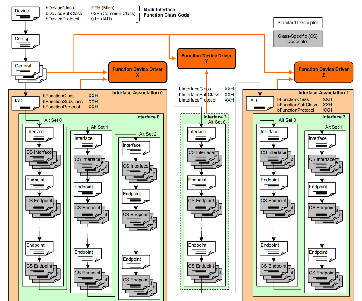
__ALIGN_BEGIN const uint8_t USBD_FS_DeviceDesc[USB_LEN_DEV_DESC] __ALIGN_END = { 0x12, /*bLength */ USB_DESC_TYPE_DEVICE, /*bDescriptorType*/ 0x00, /*bcdUSB */ 0x02, 0xEF, /*bDeviceClass*/ 0x02, /*bDeviceSubClass*/ 0x01, /*bDeviceProtocol*/ USB_MAX_EP0_SIZE, /*bMaxPacketSize*/ LOBYTE(USBD_VID), /*idVendor*/ HIBYTE(USBD_VID), /*idVendor*/ LOBYTE(USBD_PID), /*idVendor*/ HIBYTE(USBD_PID), /*idVendor*/ 0x00, /*bcdDevice rel. 2.00*/ 0x02, USBD_IDX_MFC_STR, /*Index of manufacturer string*/ USBD_IDX_PRODUCT_STR, /*Index of product string*/ USBD_IDX_SERIAL_STR, /*Index of serial number string*/ USBD_MAX_NUM_CONFIGURATION /*bNumConfigurations*/ }; In general, everything is the same here, only the fields that define the device class (bDeviceClass) differ. Now these fields indicate that this is a composite device. The host will need to work hard to figure out all the other descriptors and load the correct drivers for each of the components. The bDeviceProtocol field means that parts of the composite device will be described by a special descriptor — the Interface Association Descriptor. About him a little lower.
The configuration descriptor is about the same as before, the difference is only in the number of interfaces. Now we have them 3
Configuration descriptor
#define USB_MSC_CDC_CONFIG_DESC_SIZ 98 /* USB MSC+CDC device Configuration Descriptor */ static const uint8_t USBD_MSC_CDC_CfgDesc[USB_MSC_CDC_CONFIG_DESC_SIZ] = { 0x09, /* bLength: Configuation Descriptor size */ USB_DESC_TYPE_CONFIGURATION, /* bDescriptorType: Configuration */ USB_MSC_CDC_CONFIG_DESC_SIZ, /* wTotalLength: Bytes returned */ 0x00, 0x03, /*bNumInterfaces: 3 interface*/ 0x01, /*bConfigurationValue: Configuration value*/ 0x02, /*iConfiguration: Index of string descriptor describing the configuration*/ 0xC0, /*bmAttributes: bus powered and Supports Remote Wakeup */ 0x32, /*MaxPower 100 mA: this current is used for detecting Vbus*/ /* 09 bytes */ MSC. ( MSC CDC). , , . . , . .
MSC
/******************** Mass Storage interface ********************/ 0x09, /* bLength: Interface Descriptor size */ 0x04, /* bDescriptorType: */ MSC_INTERFACE_IDX, /* bInterfaceNumber: Number of Interface */ 0x00, /* bAlternateSetting: Alternate setting */ 0x02, /* bNumEndpoints*/ 0x08, /* bInterfaceClass: MSC Class */ 0x06, /* bInterfaceSubClass : SCSI transparent command set*/ 0x50, /* nInterfaceProtocol */ USBD_IDX_INTERFACE_STR, /* iInterface: */ /* 09 bytes */ /******************** Mass Storage Endpoints ********************/ 0x07, /*Endpoint descriptor length = 7*/ 0x05, /*Endpoint descriptor type */ MSC_IN_EP, /*Endpoint address (IN, address 1) */ 0x02, /*Bulk endpoint type */ LOBYTE(USB_MAX_PACKET_SIZE), HIBYTE(USB_MAX_PACKET_SIZE), 0x00, /*Polling interval in milliseconds */ /* 07 bytes */ 0x07, /*Endpoint descriptor length = 7 */ 0x05, /*Endpoint descriptor type */ MSC_OUT_EP, /*Endpoint address (OUT, address 1) */ 0x02, /*Bulk endpoint type */ LOBYTE(USB_MAX_PACKET_SIZE), HIBYTE(USB_MAX_PACKET_SIZE), 0x00, /*Polling interval in milliseconds*/ /* 07 bytes */ MSC , .
— IAD (Interface Association Descriptor) – . , .
/******** IAD should be positioned just before the CDC interfaces ****** IAD to associate the two CDC interfaces */ 0x08, /* bLength */ 0x0B, /* bDescriptorType */ CDC_INTERFACE_IDX, /* bFirstInterface */ 0x02, /* bInterfaceCount */ 0x02, /* bFunctionClass */ 0x02, /* bFunctionSubClass */ 0x01, /* bFunctionProtocol */ 0x00, /* iFunction (Index of string descriptor describing this function) */ /* 08 bytes */ This tricky descriptor tells the host that the description of the previous function of the USB device (MSC) has ended and now there will be a completely different function. And it is immediately indicated which one - CDC. It also indicates the number of interfaces associated with it and the index of the first one.
IAD descriptor is not needed for MSC, because there is only one interface. But IAD is needed for CDC to group 2 interfaces into one function. This is stated in the specification of this descriptor.
Finally, the CDC descriptors. They fully correspond to the descriptors for a single CDC function with an accuracy of interface and endpoint numbers.
CDC Descriptors
/******************** CDC interfaces ********************/ /*Interface Descriptor */ 0x09, /* bLength: Interface Descriptor size */ USB_DESC_TYPE_INTERFACE, /* bDescriptorType: Interface */ /* Interface descriptor type */ CDC_INTERFACE_IDX, /* bInterfaceNumber: Number of Interface */ 0x00, /* bAlternateSetting: Alternate setting */ 0x01, /* bNumEndpoints: One endpoints used */ 0x02, /* bInterfaceClass: Communication Interface Class */ 0x02, /* bInterfaceSubClass: Abstract Control Model */ 0x01, /* bInterfaceProtocol: Common AT commands */ 0x01, /* iInterface: */ /* 09 bytes */ /*Header Functional Descriptor*/ 0x05, /* bLength: Endpoint Descriptor size */ 0x24, /* bDescriptorType: CS_INTERFACE */ 0x00, /* bDescriptorSubtype: Header Func Desc */ 0x10, /* bcdCDC: spec release number */ 0x01, /* 05 bytes */ /*Call Management Functional Descriptor*/ 0x05, /* bFunctionLength */ 0x24, /* bDescriptorType: CS_INTERFACE */ 0x01, /* bDescriptorSubtype: Call Management Func Desc */ 0x00, /* bmCapabilities: D0+D1 */ CDC_INTERFACE_IDX + 1, /* bDataInterface: 2 */ /* 05 bytes */ /*ACM Functional Descriptor*/ 0x04, /* bFunctionLength */ 0x24, /* bDescriptorType: CS_INTERFACE */ 0x02, /* bDescriptorSubtype: Abstract Control Management desc */ 0x02, /* bmCapabilities */ /* 04 bytes */ /*Union Functional Descriptor*/ 0x05, /* bFunctionLength */ 0x24, /* bDescriptorType: CS_INTERFACE */ 0x06, /* bDescriptorSubtype: Union func desc */ CDC_INTERFACE_IDX, /* bMasterInterface: Communication class interface */ CDC_INTERFACE_IDX + 1, /* bSlaveInterface0: Data Class Interface */ /* 05 bytes */ /*Endpoint 2 Descriptor*/ 0x07, /* bLength: Endpoint Descriptor size */ USB_DESC_TYPE_ENDPOINT, /* bDescriptorType: Endpoint */ CDC_CMD_EP, /* bEndpointAddress */ 0x03, /* bmAttributes: Interrupt */ LOBYTE(CDC_CMD_PACKET_SIZE), /* wMaxPacketSize: */ HIBYTE(CDC_CMD_PACKET_SIZE), 0x10, /* bInterval: */ /* 07 bytes */ /*Data class interface descriptor*/ 0x09, /* bLength: Endpoint Descriptor size */ USB_DESC_TYPE_INTERFACE, /* bDescriptorType: */ CDC_INTERFACE_IDX + 1, /* bInterfaceNumber: Number of Interface */ 0x00, /* bAlternateSetting: Alternate setting */ 0x02, /* bNumEndpoints: Two endpoints used */ 0x0A, /* bInterfaceClass: CDC */ 0x00, /* bInterfaceSubClass: */ 0x00, /* bInterfaceProtocol: */ 0x00, /* iInterface: */ /* 09 bytes */ /*Endpoint OUT Descriptor*/ 0x07, /* bLength: Endpoint Descriptor size */ USB_DESC_TYPE_ENDPOINT, /* bDescriptorType: Endpoint */ CDC_OUT_EP, /* bEndpointAddress */ 0x02, /* bmAttributes: Bulk */ LOBYTE(CDC_DATA_PACKET_SIZE), /* wMaxPacketSize: */ HIBYTE(CDC_DATA_PACKET_SIZE), 0x00, /* bInterval: ignore for Bulk transfer */ /* 07 bytes */ /*Endpoint IN Descriptor*/ 0x07, /* bLength: Endpoint Descriptor size */ USB_DESC_TYPE_ENDPOINT, /* bDescriptorType: Endpoint */ CDC_IN_EP, /* bEndpointAddress */ 0x02, /* bmAttributes: Bulk */ LOBYTE(CDC_DATA_PACKET_SIZE), /* wMaxPacketSize: */ HIBYTE(CDC_DATA_PACKET_SIZE), 0x00, /* bInterval */ /* 07 bytes */ When all the descriptors are ready, you can calculate the total size of the configuration.
#define USB_CDC_CONFIG_DESC_SIZ 98 Let's move on to writing code. USB core communicates with class drivers using this interface
Class driver interface
typedef struct _Device_cb { uint8_t (*Init) (struct _USBD_HandleTypeDef *pdev , uint8_t cfgidx); uint8_t (*DeInit) (struct _USBD_HandleTypeDef *pdev , uint8_t cfgidx); /* Control Endpoints*/ uint8_t (*Setup) (struct _USBD_HandleTypeDef *pdev , USBD_SetupReqTypedef *req); uint8_t (*EP0_TxSent) (struct _USBD_HandleTypeDef *pdev ); uint8_t (*EP0_RxReady) (struct _USBD_HandleTypeDef *pdev ); /* Class Specific Endpoints*/ uint8_t (*DataIn) (struct _USBD_HandleTypeDef *pdev , uint8_t epnum); uint8_t (*DataOut) (struct _USBD_HandleTypeDef *pdev , uint8_t epnum); uint8_t (*SOF) (struct _USBD_HandleTypeDef *pdev); uint8_t (*IsoINIncomplete) (struct _USBD_HandleTypeDef *pdev , uint8_t epnum); uint8_t (*IsoOUTIncomplete) (struct _USBD_HandleTypeDef *pdev , uint8_t epnum); const uint8_t *(*GetHSConfigDescriptor)(uint16_t *length); const uint8_t *(*GetFSConfigDescriptor)(uint16_t *length); const uint8_t *(*GetOtherSpeedConfigDescriptor)(uint16_t *length); const uint8_t *(*GetDeviceQualifierDescriptor)(uint16_t *length); #if (USBD_SUPPORT_USER_STRING == 1) uint8_t *(*GetUsrStrDescriptor)(struct _USBD_HandleTypeDef *pdev ,uint8_t index, uint16_t *length); #endif } USBD_ClassTypeDef; Depending on the status or event on the USB bus, the kernel calls the appropriate function.
Any architectural problem can be solved by introducing an additional abstract layer ... (C) another anecdote.
Of course, we will not implement all the functionality entirely - the existing code will be responsible for the implementation of the CDC and MSC classes. We will only write an interlayer that will redirect calls to either one or another implementation.
Initialization and Deinitialization
/** * @brief USBD_MSC_CDC_Init * Initialize the MSC+CDC interface * @param pdev: device instance * @param cfgidx: Configuration index * @retval status */ static uint8_t USBD_MSC_CDC_Init (USBD_HandleTypeDef *pdev, uint8_t cfgidx) { /* MSC initialization */ uint8_t ret = USBD_MSC_Init (pdev, cfgidx); if(ret != USBD_OK) return ret; /* CDC initialization */ ret = USBD_CDC_Init (pdev, cfgidx); if(ret != USBD_OK) return ret; return USBD_OK; } /** * @brief USBD_MSC_CDC_Init * DeInitialize the MSC+CDC layer * @param pdev: device instance * @param cfgidx: Configuration index * @retval status */ static uint8_t USBD_MSC_CDC_DeInit (USBD_HandleTypeDef *pdev, uint8_t cfgidx) { /* MSC De-initialization */ USBD_MSC_DeInit(pdev, cfgidx); /* CDC De-initialization */ USBD_CDC_DeInit(pdev, cfgidx); return USBD_OK; } Everything is simple: we initialize (deinitialize) both classes. Called functions themselves will create / delete their endpoints.
Perhaps the most difficult function will be Setup.
Setup Handler
/** * @brief USBD_MSC_CDC_Setup * Handle the MSC+CDC specific requests * @param pdev: instance * @param req: usb requests * @retval status */ static uint8_t USBD_MSC_CDC_Setup (USBD_HandleTypeDef *pdev, USBD_SetupReqTypedef *req) { // Route requests to MSC interface or its endpoints to MSC class implementaion if(((req->bmRequest & USB_REQ_RECIPIENT_MASK) == USB_REQ_RECIPIENT_INTERFACE && req->wIndex == MSC_INTERFACE_IDX) || ((req->bmRequest & USB_REQ_RECIPIENT_MASK) == USB_REQ_RECIPIENT_ENDPOINT && ((req->wIndex & 0x7F) == MSC_EP_IDX))) { return USBD_MSC_Setup(pdev, req); } return USBD_CDC_Setup(pdev, req); } This is a callback to one of the standard requests on the USB bus, but this request is very multifaceted. It can be both data acquisition (get), and installation (Set). This may be a request to the device as a whole, to one of its interfaces or endpoints. It can also come here as a standard request defined by the basic specification of USB, and specific to a particular device or class. Read more here (Section “Setup Package”).
- Setup . if switch. USB 3-4 ( ). , .
, , . — wIndex , , wIndex . .
By the way, in order for this to work, you need not to forget to change the default, which determines the number of interfaces, otherwise the request will simply not reach and cut off inside the USB core
#define USBD_MAX_NUM_INTERFACES 3 DataIn and DataOut are all easier. There is the number of the end point - by it and we determine where the request is redirected
DataIn () and DataOut ()
/** * @brief USBD_MSC_CDC_DataIn * handle data IN Stage * @param pdev: device instance * @param epnum: endpoint index * @retval status */ static uint8_t USBD_MSC_CDC_DataIn (USBD_HandleTypeDef *pdev, uint8_t epnum) { if(epnum == MSC_EP_IDX) return USBD_MSC_DataIn(pdev, epnum); return USBD_CDC_DataIn(pdev, epnum); } /** * @brief USBD_MSC_CDC_DataOut * handle data OUT Stage * @param pdev: device instance * @param epnum: endpoint index * @retval status */ static uint8_t USBD_MSC_CDC_DataOut (USBD_HandleTypeDef *pdev, uint8_t epnum) { if(epnum == MSC_EP_IDX) return USBD_MSC_DataOut(pdev, epnum); return USBD_CDC_DataOut(pdev, epnum); } Please note that the transmission direction flag in the endpoint number is not used. Those.even if some functions use MSC_IN_EP (0x81), then in this function you need to use MSC_EP_IDX (0x01).
Sometimes the data comes to the zero end point and for this there is a special callback. I don’t know what I would do if both classes (both CDC and MSC) had handlers for this case - the interface or endpoint number was not specified in such a request. It would be impossible to understand to whom the request is addressed. The benefit of such a request is able to handle only the CDC class - so we will send it
EP0_RxReady Handler
/** * @brief USBD_MSC_CDC_EP0_RxReady * handle EP0 Rx Ready event * @param pdev: device instance * @retval status */ static uint8_t USBD_MSC_CDC_EP0_RxReady (USBD_HandleTypeDef *pdev) { return USBD_CDC_EP0_RxReady(pdev); } No longer will we have non-trivial handlers. There are a couple of getters for the descriptors, but their code is standard and not of interest. Fill in the "virtual functions table"
Function pointers table
USBD_ClassTypeDef USBD_MSC_CDC_ClassDriver = { USBD_MSC_CDC_Init, USBD_MSC_CDC_DeInit, USBD_MSC_CDC_Setup, NULL, //USBD_MSC_CDC_EP0_TxReady, USBD_MSC_CDC_EP0_RxReady, USBD_MSC_CDC_DataIn, USBD_MSC_CDC_DataOut, NULL, //USBD_MSC_CDC_SOF, NULL, //USBD_MSC_CDC_IsoINIncomplete, NULL, //USBD_MSC_CDC_IsoOutIncomplete, USBD_MSC_CDC_GetCfgDesc, USBD_MSC_CDC_GetCfgDesc, USBD_MSC_CDC_GetCfgDesc, USBD_MSC_CDC_GetDeviceQualifierDesc, }; Now the initialization code
Initialization code
USBD_Init(&hUsbDeviceFS, &FS_Desc, 0); USBD_RegisterClass(&hUsbDeviceFS, &USBD_MSC_CDC_ClassDriver); USBD_CDC_RegisterInterface(&hUsbDeviceFS, &USBD_Interface_fops_FS); USBD_MSC_RegisterStorage(&hUsbDeviceFS, &SdMscDriver); USBD_Start(&hUsbDeviceFS); USB , . Everything? . .
The point is this. – , , . – USB ( , ). USB
USB
/* USB Device handle structure */ typedef struct _USBD_HandleTypeDef { ... void *pClassData; void *pUserData; void *pData; } USBD_HandleTypeDef; The problem is that each class considers these fields as its own and clings its structure there.
This can be solved in several ways. Comrades from here generally pushed all the code from both drivers (CDC and MSC) into their class implementation in order to figure out what was happening. Another approach is to put structures in these fields in which there is room for both classes of data. Here this approach is partially used, in addition another part of the data is transferred to global variables (which is ok, if we have only one USB port).
We will probably take a simpler path. If class drivers want exclusive fields, we’ll give them these fields.
'Right' USB Handle Fields
typedef struct _USBD_HandleTypeDef { ... USBD_MSC_BOT_HandleTypeDef *pClassDataMSC; const USBD_StorageTypeDef *pClassSpecificInterfaceMSC; USBD_CDC_HandleTypeDef *pClassDataCDC; const USBD_CDC_ItfTypeDef *pClassSpecificInterfaceCDC; PCD_HandleTypeDef *pPCDHandle; } USBD_HandleTypeDef; First of all, I gave each class its own fields - let them be tormented as they want. Secondly, I named these fields according to the fact that there really is in them - no UserData there, but a pointer to the interface.
Of course, on the pros, it would be more beautiful and elegant (with the same memory consumption and memory). but also on C can be done humanly. Since I launched my little hands into the handle structure, I changed the incomprehensible void * to human types (by the way, the void * pData field is now humanly called pPCDHandle with the corresponding type). And const also placed where necessary. It was necessary, however, to tinker with forward declarations.
About the organization of the project. In some IDE projects can be built as follows. The USB library and source code for the class drivers come with the STM32 Cube, but some of the files are suggested to be written to the user. It may happen that the library lies somewhere in a common location and is used by several projects. It should be understood that I now we are changing the code of the USB library and therefore it is better to have our own copy so as not to disturb anyone.
Of course, renaming fields should be reflected in the driver code. But here everything is just simple - contextual replacement solves the problem.
The main thing is not to overdo it. I changed hands, looking through each use. There I found a "bug" in the code, I fixed it and then I debugged 3 days in an attempt to understand why it was not working.
Type 'bug'
USBD_StatusTypeDef USBD_LL_Reset(USBD_HandleTypeDef *pdev) { ... if (pdev->pClassData) pdev->pClass->DeInit(pdev, pdev->dev_config); ... } – pClassData, pClass. «» ( pClass), . Those. pClassData , .
. Init() pClassDataXXX, .
UPDATE: , fronders .
(CDC, HID, MSC, ) ( USBD_CDC_Init() ) pClassDataXXX USBD_malloc(), malloc(). — .
USBD_CDC_Init()
static uint8_t USBD_CDC_Init (USBD_HandleTypeDef *pdev, uint8_t cfgidx) { ... pdev->pClassData = USBD_malloc(sizeof (USBD_CDC_HandleTypeDef)); ... } But, in some projects (including examples from STMicroelectronics itself) they decided to save on memory and wrote their implementation of the allocator
not very correct allocator
void *USBD_static_malloc(uint32_t size) { static uint32_t mem[(sizeof(USBD_CDC_HandleTypeDef)/4+1)];/* On 32-bit boundary */ return mem; } In principle, this approach will work, but only for the time being we have only one class of device. As soon as several classes try to “allocate” memory through such an allocator, everything will break, because several classes will torment the same buffer.
In fact, it will be necessary to allocate memory only if you build a device with several identical functions - for example, a device that implements two or more CDCs. Well, maybe this is still needed in some exotic cases, when interfaces are created and deleted on the fly. In all other cases (of which the vast majority) I would not bother with the allocation of memory and distributed the buffer statically. In my project, I did this (at the same time, the types of data are whitened-colored):
static allocation
// A CDC object USBD_CDC_HandleTypeDef cdcInstance; ... uint8_t USBD_CDC_Init (USBD_HandleTypeDef *pdev, uint8_t cfgidx) { ... pdev->pClassDataCDC = &cdcInstance; hcdc = pdev->pClassDataCDC; ... } Final Touch - PMA Buffer Distribution
PMA distribution
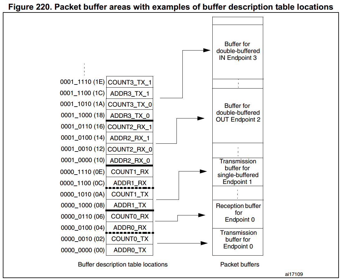
HAL_PCDEx_PMAConfig(pdev->pPCDHandle , 0x00 , PCD_SNG_BUF, 0x20); HAL_PCDEx_PMAConfig(pdev->pPCDHandle , 0x80 , PCD_SNG_BUF, 0x60); HAL_PCDEx_PMAConfig(pdev->pPCDHandle , MSC_IN_EP, PCD_SNG_BUF, 0xA0); HAL_PCDEx_PMAConfig(pdev->pPCDHandle , MSC_OUT_EP, PCD_SNG_BUF, 0xE0); HAL_PCDEx_PMAConfig(pdev->pPCDHandle, CDC_CMD_EP, PCD_SNG_BUF, 0x100); HAL_PCDEx_PMAConfig(pdev->pPCDHandle, CDC_IN_EP, PCD_SNG_BUF, 0x140); HAL_PCDEx_PMAConfig(pdev->pPCDHandle, CDC_OUT_EP, PCD_SNG_BUF, 0x180); For our endpoints, we need 7 buffers - 2 to the zero end point (control point), 2 to the MSC and 3 to the CDC. But the most interesting thing here is the starting addresses (the last parameter). For some reason, this nuance is carefully managed with all tutorials. The datasheet is written about the allocation of buffers in PMA and how it looks at the register level, but there is no information on how to use the corresponding functions from the HAL. We fill this gap.
So. — PMA (Packet Memory Area). , USB ( ). , .. . BTABLE . PMA. PMA, HAL .
Reference Manual STM32F103
, ? . 4 16- ( 2 2 , ). 4 — , MSC CDC ( — 7 — , , ). 4 * 4 * 2 = 32 .
As I said, HAL can only locate the PMA area at the beginning. So we can arrange the first buffer only at offset 0x20 (32 bytes is the size of the table). Endpoint buffers can be placed anywhere in PMA memory, as long as they do not fit each other. Each endpoint determines the maximum packet size that it is ready to process, the buffer must be equal to or larger than this size.
I allocated the buffer in 64-byte increments (the maximum buffer size recommended for USB Full Speed devices), but for some endpoints it could have been smaller. So, there is not a lot of data running on the control CDC endpoint (CDC_CMD_PACKET_SIZE is 8 bytes), so the buffer can be made only 8 bytes. However, I was not sorry, and 32 bytes - just to get round numbers.
. , 2 . . . Mass Storage , CDC — .
— . - . ( usbser.sys)
. STMicroelectronics Virtual COM Port ST. C:\Program Files (x86)\STMicroelectronics\Software\Virtual comport driver, stmcdc.inf — .
%DESCRIPTION%=DriverInstall,USB\VID_0483&PID_5740Here it connects our VID / PID with the device driver. Only this is not enough - you must also specify the interface number that manages the CDC. In my case, this is the first interface (zero is responsible for the MSC). For this line should look like
%DESCRIPTION%=DriverInstall,USB\VID_0483&PID_5741&MI_01In fact, the original string can not be changed, but simply
add a line to the appropriate section.
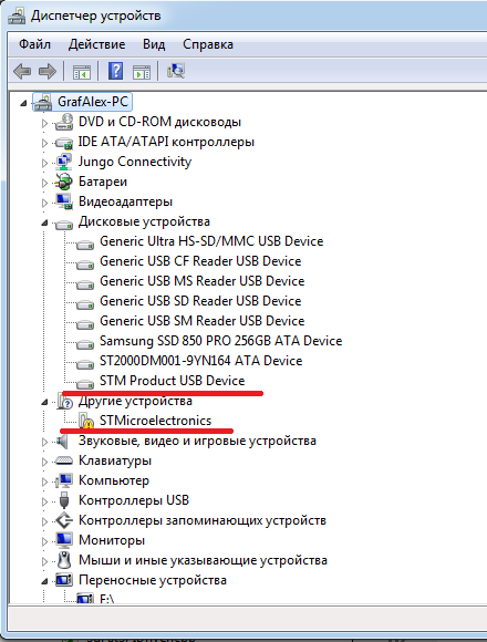
After all the preparations, we find a non-working device in the list of devices, please update the driver, specify the directory where the inf file is located and voila - the driver is installed. Windows itself assigns the name COMxx to this device - you can take your favorite terminalka and open this COM port.
Everything is easier with Linux - everything starts there without dancing with
UPDATE from fronders: in Windows10 also everything starts up on its own. Moreover, ST themselves do not recommend their vcp driver for 10s and suggest using the standard one.
Conclusion
On some forums, I saw messages like “how everything in this USB is difficult, some drivers ... I’m better on registers.” Guys, not everything is so simple. The register level is probably the easiest part. But besides it there is a huge layer of logic that the device must implement. And here already without knowledge of the protocols and many hundreds of pages of specifications in any way.
But it is not all that bad.People have already taken care of and written all the logic. In most cases, it remains only to substitute the necessary values and correct some parameters. Yes, the library from ST is one more monster. But after a thoughtful reading of USB In A Nutshell, a couple of specifications of a particular class of devices and work with a sniffer, many things fall into place. The library begins to look more or less slender. You can even make a custom class driver with relatively small efforts, which we did with success.
I did an implementation of a composite CDC + MSC device, but approximately the same approach can be applied to other combinations - CDC + HID, MSC + Audio, CDC + MSC + HID and others. My implementation is designed to work on microcontrollers of the STM32F103 series, but the principle itself can be adapted for other microcontrollers (including and not STM32).
In this article, I did not set myself the task of telling how USB works in all details - firstly, there are articles and books that tell it better (I touched only a small part), and secondly, it is better to draw a lot of things from the original sources (specifications) .
Instead of retelling the specifications, I tried to describe how the ST stack's USB implementation works. I also tried to draw attention to special moments and to tell why it is done this way.
I have long doubted whether to put a tick "Tutorial". On the one hand, I give recommendations and step-by-step instructions, draw attention to special moments and give references to the original sources. On the other hand, I cannot provide a ready-made library for downloading and embedding in my projects.
, , . , , , , . USB , ST. . , — , , , .
, . , !
Source: https://habr.com/ru/post/335018/
All Articles