How the KOMPAS-3D math library turned into a C3D Toolkit for CAD developers → part 1
In previous posts, we talked about how the KOMPAS-3D CAD system is being developed and tested . Additionally, a series of articles on application development using the KOMPAS-3D API has been launched. It's time to talk about the "stuffing" that manages all the constructions in KOMPAS - the core of the geometric modeling C3D or just the geometric core of C3D.
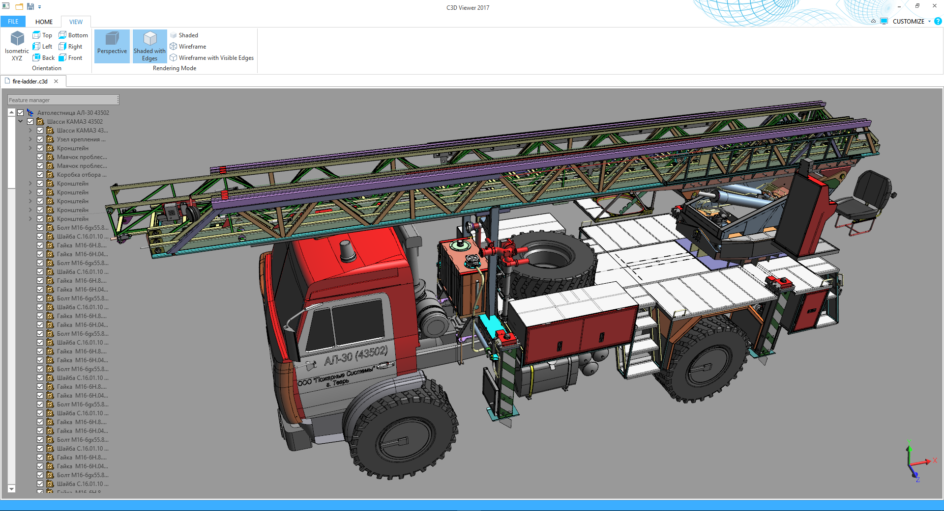
Fire ladder AL-30 (manufacturer: LLC Fire Systems)
The application programming interface API in the CAD system allows you to expand the capabilities of the design system and contributes to a significant reduction in the development time of additional software components to the existing CAD system in the enterprise. This is achieved through the use of a ready-made set of functions, presented in a convenient and understandable for the developer form. As a rule, the internal implementation of such functions is hidden from the API programmer-user and is an object of intellectual property of the owner of the source software codes.
The features of working with the application programming interface are specified in the technical documentation. It also indicates which values need to be fed to the input of a particular function in order to get the correct values on the output according to the purpose of this function. That is, the API allows to abstract from the implementation of individual program blocks when developing applications:
')

Working with the API-interface on the principle of "black box"
Due to the fact that KOMPAS-3D has its own API, the basic functionality of the system over time has been supplemented with applications for designing electronic equipment and electrical equipment, machine parts, pipelines, metal structures, buildings and structures for various purposes.
But using the CAD API is not always convenient and expedient. The fact is that when referring to the geometric functions of the kernel, the developer directly eliminates the need to interact with intermediate links of the CAD system, such as the graphical interface, specifications, etc. Therefore, the same geometry in the kernel is created faster than in the CAD API. Also, the use of a geometric kernel allows engineering application developers to keep secret the know-how invented by them. For example, the features of constructing complex geometric models can be easily hidden from the user's attention.
Most modern CAD systems are based on the 3D model building tree, which means that each new operation leads to the rebuilding of the entire tree, so using the kernel it is much easier to carry out iterative constructions, in particular, the creation of gears:

Bevel gear built by the Shaft application without using a geometric kernel: multiple build operations are hidden in the macro element
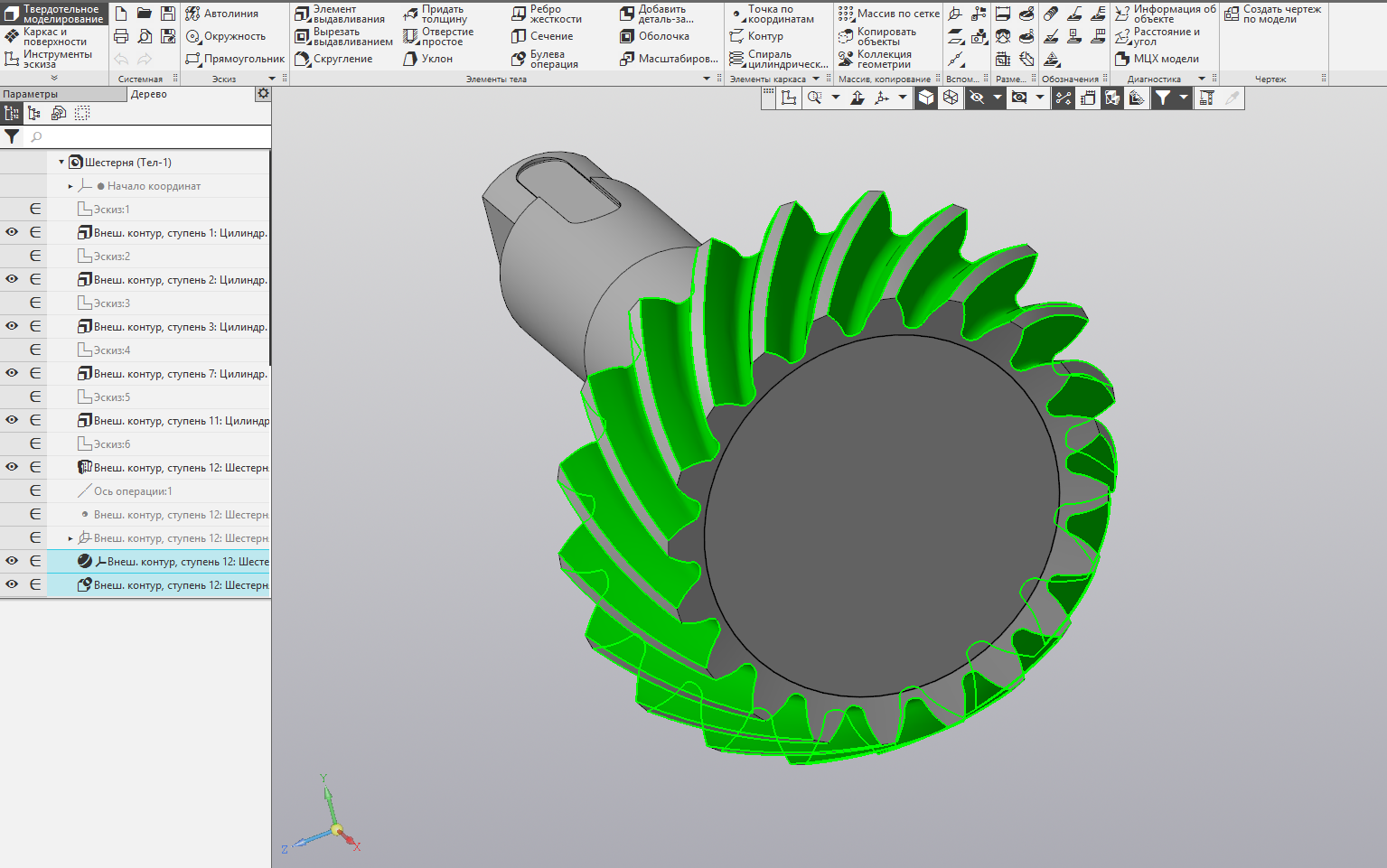
Bevel gear, built by the application "Shafts and mechanical gears" using the functionality of the geometric core: to build a ring gear requires only two operations (Picture is clickable)
In the case of the Shafts and Mechanical Transmissions application, using the kernel allows developers to:
In general, with the use of a geometric kernel in development, the probability of a model breaking when the user changes the application version decreases, and in general, the stability of the program increases with unpredictable user actions. And the inclusion of the mathematical library in the basis of the developed solution allows to ensure independence from existing programs. At a minimum, this means that you do not have to drag a third-party (often heavy) system distributive to the project and make license deductions for using the associated CAD system. However, the latter statement cannot be considered a weighty argument, since application developers often focus on the audience of a specific CAD, CAM or CAE system, sometimes reaching values of tens and hundreds of thousands of active users.
The set of geometric functions in CAD forms together the geometric core of the system, which differs from the game engine with realistic 3D graphics. This is most clearly demonstrated through an analogy with graphic editors. As you know, some of them work with raster graphics based on points. Other editors use vector graphics that are based on curved lines. Similarly, in 3D applications, there is polygonal graphics, which is based on the position of points in space (polygons are built from them), and spline graphics, which is a combination of mathematical formulas and equations.
In terms of CAD, we can say that polygonal graphics are based on a faceted representation of geometry. The same presentation is used in game engines and in various animation packages for creating special effects of cinema:

Faceted representation of 3D-model geometry
A mathematically accurate description of a 3D model is given by the boundary representation. Its main feature is that to represent the shape of a geometric model, a set of faces is used, passing along the border that separates the interior of the object being modeled from the rest of the space. As you probably already guessed, it is this representation that is used in geometric kernels.

Boundary representation of the geometry of a 3D model
There are three main reasons:
Scalable .
The accuracy of the display of the model in the boundary representation is determined at the CAD level, and the calculation of the polygonal grids is made so that the model visually appears smooth. In this case, if we take the original polygonal model, then, regardless of the chosen design system, when we increase the scale, we will first see increasing triangles, and then the model will become angular. The restriction in this case is set at the level of the model itself - with what accuracy the grid was originally calculated, for example, when writing to the STL format, with such precision you will have to work further.
Hunting in natural size. When the model is enlarged, all faces retain their shape (the image is clickable)
Smoothness
An example of transferring a facet model to a drawing. You can see how the places of grid thickening merge (Picture is clickable)
Accuracy

Processing a model in an Esprit CAM system
Actually, there are much more reasons, but these are professional subtleties.
Unbelievable, but true: modern design systems (and KOMPAS-3D are not an exception) work with two representations of geometry. The boundary representation is used in the modeling process, after which the triangulation grid is calculated and a polygonal model is built, which is then sent to the video card to draw the visual scene. At this stage, the visualization core can interfere with the process, for example, C3D Vision, which is responsible for managing the drawing of the model using mathematical, software and hardware optimization tools. More about this we will tell in the following articles.
Every engineering software developer sooner or later faces a choice: do you have to write the necessary mathematical algorithms yourself or buy ready-made components on the side? In the history of ASCON, the use of third-party modules was considered in 1995, when the development of KOMPAS-3D was discussed. Then a thorny let was chosen for independent writing of geometric functions, which are based on rather complicated mathematics. You can learn more about it by reading the book on geometric modeling by Nikolai Golovanov :


The table of contents and the cover of the book "Geometric modeling" N.N. Golovanova (Pictures are clickable)
Few people know that later, in the 2000s, ASCON re-considered the issue of using a third-party mathematical core for working with 3D. Testing of the CAD components available on the market was made and a strategically important decision was made to continue developing our own geometric core. It was named C3D, which is short for the core corporate project name “Core3D”. Today this core is successfully used not only inside ASCON, but also in projects of other developers of computer-aided design systems in Russia and abroad.
The second part of the article

Arkady Kamnev
Marketing Manager at C3D Labs
Fire ladder AL-30 (manufacturer: LLC Fire Systems)
Why do you need a geometric core when you have access to the CAD-system API?
The application programming interface API in the CAD system allows you to expand the capabilities of the design system and contributes to a significant reduction in the development time of additional software components to the existing CAD system in the enterprise. This is achieved through the use of a ready-made set of functions, presented in a convenient and understandable for the developer form. As a rule, the internal implementation of such functions is hidden from the API programmer-user and is an object of intellectual property of the owner of the source software codes.
The features of working with the application programming interface are specified in the technical documentation. It also indicates which values need to be fed to the input of a particular function in order to get the correct values on the output according to the purpose of this function. That is, the API allows to abstract from the implementation of individual program blocks when developing applications:
')
Working with the API-interface on the principle of "black box"
Due to the fact that KOMPAS-3D has its own API, the basic functionality of the system over time has been supplemented with applications for designing electronic equipment and electrical equipment, machine parts, pipelines, metal structures, buildings and structures for various purposes.
But using the CAD API is not always convenient and expedient. The fact is that when referring to the geometric functions of the kernel, the developer directly eliminates the need to interact with intermediate links of the CAD system, such as the graphical interface, specifications, etc. Therefore, the same geometry in the kernel is created faster than in the CAD API. Also, the use of a geometric kernel allows engineering application developers to keep secret the know-how invented by them. For example, the features of constructing complex geometric models can be easily hidden from the user's attention.
Most modern CAD systems are based on the 3D model building tree, which means that each new operation leads to the rebuilding of the entire tree, so using the kernel it is much easier to carry out iterative constructions, in particular, the creation of gears:
Bevel gear built by the Shaft application without using a geometric kernel: multiple build operations are hidden in the macro element
Bevel gear, built by the application "Shafts and mechanical gears" using the functionality of the geometric core: to build a ring gear requires only two operations (Picture is clickable)
In the case of the Shafts and Mechanical Transmissions application, using the kernel allows developers to:
- reduce the time to create three-dimensional geometry;
- increase the accuracy of calculations difficult to form models;
- automatically carry out measurements of measuring dimensions of gears, as well as perform invisible constructions necessary for calculating gears.
In general, with the use of a geometric kernel in development, the probability of a model breaking when the user changes the application version decreases, and in general, the stability of the program increases with unpredictable user actions. And the inclusion of the mathematical library in the basis of the developed solution allows to ensure independence from existing programs. At a minimum, this means that you do not have to drag a third-party (often heavy) system distributive to the project and make license deductions for using the associated CAD system. However, the latter statement cannot be considered a weighty argument, since application developers often focus on the audience of a specific CAD, CAM or CAE system, sometimes reaching values of tens and hundreds of thousands of active users.
Geometric and game cores
The set of geometric functions in CAD forms together the geometric core of the system, which differs from the game engine with realistic 3D graphics. This is most clearly demonstrated through an analogy with graphic editors. As you know, some of them work with raster graphics based on points. Other editors use vector graphics that are based on curved lines. Similarly, in 3D applications, there is polygonal graphics, which is based on the position of points in space (polygons are built from them), and spline graphics, which is a combination of mathematical formulas and equations.
In terms of CAD, we can say that polygonal graphics are based on a faceted representation of geometry. The same presentation is used in game engines and in various animation packages for creating special effects of cinema:
Faceted representation of 3D-model geometry
A mathematically accurate description of a 3D model is given by the boundary representation. Its main feature is that to represent the shape of a geometric model, a set of faces is used, passing along the border that separates the interior of the object being modeled from the rest of the space. As you probably already guessed, it is this representation that is used in geometric kernels.
Explanation.
In the boundary representation based on NURBS, the curves and surfaces accurately pass through the given discrete places of space (points or curves), at other points of the space, the requirement of smoothness is imposed on them. Since the source data for constructing NURBS objects are discrete, NURBS curves and surfaces in the boundary representation are considered accurate because they exactly correspond to the initial requirements. Moreover, NURBS objects can accurately represent the shape of almost all analytical curves and surfaces.
Everything for which analytical laws are known is described in the boundary representation by other objects, for example, curves and surfaces of second order. For objects that cannot be analyzed analytically, the boundary representation uses special techniques. So, for an accurate description of the intersection curve of two cubic NURBS surfaces, iterative methods are used: the intersection curve is represented by a set of points, which serve as initial approximations for determining the position of the intersection curve point with the required accuracy. Thus, the position of the points of the intersection curve with each reference to the curve is recalculated by iterative methods using the information in the curve.
UPD: A person communicates with an intersection curve, for example, two NURBS surfaces, as follows: a person reports the value of a parameter to a curve, and the curve gives a point in space corresponding to this parameter. That is, there is some information in the intersection curve (this is not necessarily a set of points, there can be intersected surfaces and some data on the curve parameter), which allows you to calculate a point at the intersection of surfaces with maximum machine precision, above which it makes no sense to specify. Accordingly, there are no piecewise linear representations, cubic curves, or approximation curves in the intersection curve. The curve of intersection of surfaces is an object that, for the specified parameter, gives a point in space.
Boundary representation of the geometry of a 3D model
But then why is polygonal graphics not suitable for a geometric kernel?
There are three main reasons:
Scalable .
Any object must be easily increased and reduced. Defects of geometry are irrelevant.
This means that at any scale of the visual scene, the image will be as smooth as the model itself. A round is always round, a corner is a corner. Violation of the stated principle implies the presence of defects.
The accuracy of the display of the model in the boundary representation is determined at the CAD level, and the calculation of the polygonal grids is made so that the model visually appears smooth. In this case, if we take the original polygonal model, then, regardless of the chosen design system, when we increase the scale, we will first see increasing triangles, and then the model will become angular. The restriction in this case is set at the level of the model itself - with what accuracy the grid was originally calculated, for example, when writing to the STL format, with such precision you will have to work further.
Hunting in natural size. When the model is enlarged, all faces retain their shape (the image is clickable)
Smoothness
The grid of triangles for working with drawings is not suitable - the drawing needs smooth and clear contours, and the grid will create visual dirt.
For example, consider the cube. When projecting its boundary representation onto a plane, we get a square. In the case of a polygonal representation, we will see a square with a diagonal. If you project a polygonal cylinder into a drawing, then there will be much more diagonals. They form the visual dirt.
An example of transferring a facet model to a drawing. You can see how the places of grid thickening merge (Picture is clickable)
Accuracy
The movement of the machine control bodies with a numerical control, which works with the 3D model, is much easier to set using mathematical formulas.
The polygonal representation of the model does not allow to build an exact trajectory of the cutting tool, since the initial information about the shape of the object being made is missing and replaced by an approximate one.
NB: There are no ready-made CAM formats that would accept NURBS as source data. There are some enthusiasts who offer their own versions of the G-code, capable of performing “NURBS interpolation”, but so far all this remains in the field of science.
NB: There are no ready-made CAM formats that would accept NURBS as source data. There are some enthusiasts who offer their own versions of the G-code, capable of performing “NURBS interpolation”, but so far all this remains in the field of science.
Processing a model in an Esprit CAM system
Actually, there are much more reasons, but these are professional subtleties.
Unbelievable, but true: modern design systems (and KOMPAS-3D are not an exception) work with two representations of geometry. The boundary representation is used in the modeling process, after which the triangulation grid is calculated and a polygonal model is built, which is then sent to the video card to draw the visual scene. At this stage, the visualization core can interfere with the process, for example, C3D Vision, which is responsible for managing the drawing of the model using mathematical, software and hardware optimization tools. More about this we will tell in the following articles.
Difficult choice: buy a core or write your own?
Every engineering software developer sooner or later faces a choice: do you have to write the necessary mathematical algorithms yourself or buy ready-made components on the side? In the history of ASCON, the use of third-party modules was considered in 1995, when the development of KOMPAS-3D was discussed. Then a thorny let was chosen for independent writing of geometric functions, which are based on rather complicated mathematics. You can learn more about it by reading the book on geometric modeling by Nikolai Golovanov :
The table of contents and the cover of the book "Geometric modeling" N.N. Golovanova (Pictures are clickable)
Few people know that later, in the 2000s, ASCON re-considered the issue of using a third-party mathematical core for working with 3D. Testing of the CAD components available on the market was made and a strategically important decision was made to continue developing our own geometric core. It was named C3D, which is short for the core corporate project name “Core3D”. Today this core is successfully used not only inside ASCON, but also in projects of other developers of computer-aided design systems in Russia and abroad.
The second part of the article
Arkady Kamnev
Marketing Manager at C3D Labs
Source: https://habr.com/ru/post/334814/
All Articles