Basics of computer networks. Subject number 8. Link Aggregation Protocol: Etherchannel

And hello again! After a short break, we continue to gnaw the granite of network science. This article focuses on the Etherchannel protocol. Within the framework of this topic, we will talk about aggregation, fault tolerance, load balancing. Topics important and interesting. I wish you a pleasant reading.
Content
1) Basic network terms, OSI network model and TCP / IP protocol stack.
2) Top-level protocols.
3) Protocols of lower levels (transport, network and channel).
4) Network devices and types of cables used.
5) The concept of IP addressing, subnet masks and their calculation.
6) The concept of VLAN, Trunk and VTP and DTP protocols.
7) Spanning Tree Protocol: STP.
8) Channel Aggregation Protocol: Etherchannel.
9) Routing: static and dynamic on the example of RIP, OSPF and EIGRP.
10) Network Address Translation: NAT and PAT.
11) Reservation protocols for the first transition: FHRP.
12) Computer network security and virtual private networks: VPN.
13) Global networks and protocols used: PPP, HDLC, Frame Relay.
14) Introduction to IPv6 configuration and routing.
15) Network management and network monitoring.
PS Perhaps over time, the list will be added.
So let's start with a simple one.
Etherchannel is a technology that allows you to combine (aggregate) several physical wires (channels, ports) into a single logical interface. Typically, this is used to increase resiliency and increase channel capacity. Usually, to connect critical nodes (switch-switch, switch-server, etc.). The very word Etherchannel introduced by Cisco and everything related to aggregation, it includes it. Other vendors call aggregation differently. Huawei calls it Link Aggregation, D-Link calls LAG and so on. But the essence does not change.
')
Let us analyze the work of aggregation in more detail.
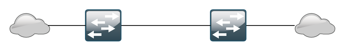
There are 2 switches connected together by one wire. Networks of departments and groups are connected to both switches (size is not important). The main thing is that there are a number of users behind the switches. These users are actively working and communicating with each other. Accordingly, in no case can they remain without communication. There are 2 questions:
- If the link between the switches fails, the connection will be lost. The work will rise, and the administrator in fear will run to understand what is the matter.
- The second question is not so critical, but with a reserve for the future. The company is growing, there are new employees, traffic is growing, and the channels are the same. We need to somehow increase the bandwidth.
The first thing that comes to mind is to throw a few more wires between the switches. But this campaign is fundamentally wrong. Adding redundant links will cause loops to appear on the network, as already mentioned in the previous article. One could argue that we have a wonderful family of STP protocols and they will decide everything. But this is also not entirely true. I show the example of the same Packet Tracer.
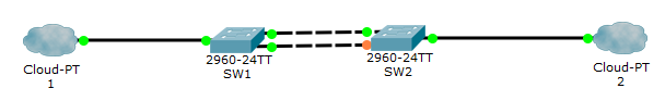
As you can see, from 2 channels, only one is active. The second will wait until it fails active. That is, we will achieve some fault tolerance, but we will not solve the issue with an increase in throughput. And the second channel will just be idle. The rule of good tone is such an approach that the elements of the network are not idle. The best solution would be to create one large logical one from several physical interfaces and drive traffic through it. And Etherchannel comes to the rescue. In Cisco OS 3 types of aggregation:
- 1) LACP or Link Aggregation Control Protocol is an open IEEE standard.
- 2) PAgP or Port Aggregation Protocol is a proprietary Cisco protocol.
- Manual aggregation.
All 3 types of aggregation will be performed only in the following cases:
- Same Duplex
- Same interface speed
- Same allowed VLANs and Native VLANs
- Same interface mode (access, trunk)
That is, the ports must be identical to each other.
Now about their differences. The first 2 allow you to dynamically agree, and in case of failure of any of the links to notify about it.
Manual aggregation is done at the administrator's risk. The switches will not coordinate anything and will rely on what the administrator has foreseen. Despite this, many vendors recommend using manual aggregation, since in any case, the rules described above must be followed in order to work properly, and the switches will not have to generate service messages for LACP or PAgP approval.
I'll start with the LACP protocol. To make it work, you need to transfer it to active or passive mode. The difference between the modes is that the active mode immediately turns on the LACP protocol, and the passive mode turns on the LACP if it detects a LACP message from a neighbor. Accordingly, in order for the aggregation to work with LACP, it is necessary that both be in active mode, or one in active and the other in passive . I will make a sign.
| Mode | Active | Passive |
|---|---|---|
| Active | Yes | Yes |
| Passive | Yes | Not |
We now turn to the lab and fix in the practical part.
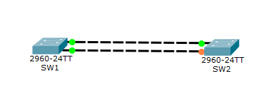
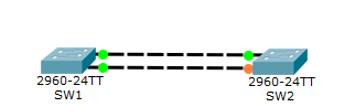
There are 2 switches connected by 2 wires. As you can see, one link is active (it is green), and the second one is backup (it is orange) due to the STP protocol. It is good, the protocol fulfills. But we want to link both links together. Then the STP protocol will assume that this is one wire and stop blocking.
We come on switches and we aggregate ports.
SW1(config)#interface fastEthernet 0/1 - SW1(config-if)#shutdown - ( , STP ) %LINK-5-CHANGED: Interface FastEthernet0/1, changed state to administratively down %LINEPROTO-5-UPDOWN: Line protocol on Interface FastEthernet0/1, changed state to down SW1(config-if)#channel-group 1 mode active - port-channel 1 ( ) active. Creating a port-channel interface Port-channel 1 - . SW1(config-if)#no shutdown - . %LINK-5-CHANGED: Interface FastEthernet0/1, changed state to up %LINEPROTO-5-UPDOWN: Line protocol on Interface FastEthernet0/1, changed state to up %LINK-5-CHANGED: Interface Port-channel 1, changed state to up %LINEPROTO-5-UPDOWN: Line protocol on Interface Port-channel 1, changed state to up SW1(config)#interface fastEthernet 0/2 - SW1(config-if)#shutdown - . %LINK-5-CHANGED: Interface FastEthernet0/2, changed state to administratively down %LINEPROTO-5-UPDOWN: Line protocol on Interface FastEthernet0/2, changed state to down SW1(config-if)#channel-group 1 mode active - port-channel 1 SW1(config-if)#no shutdown - . %LINK-5-CHANGED: Interface FastEthernet0/2, changed state to up %LINEPROTO-5-UPDOWN: Line protocol on Interface FastEthernet0/2, changed state to up The configuration on the first switch is completed on this. For accuracy, you can type the show etherchannel port-channel command:
SW1#show etherchannel port-channel Channel-group listing: ---------------------- Group: 1 ---------- Port-channels in the group: --------------------------- Port-channel: Po1 (Primary Aggregator) ------------ Age of the Port-channel = 00d:00h:08m:44s Logical slot/port = 2/1 Number of ports = 2 GC = 0x00000000 HotStandBy port = null Port state = Port-channel Protocol = LACP Port Security = Disabled Ports in the Port-channel: Index Load Port EC state No of bits ------+------+------+------------------+----------- 0 00 Fa0/1 Active 0 0 00 Fa0/2 Active 0 Time since last port bundled: 00d:00h:08m:43s Fa0/2 We see that there is such a port-channel and both interfaces are present in it.
Go to the second device.
SW2(config)#interface range fastEthernet 0/1-2 - . SW2(config-if-range)#shutdown - . %LINK-5-CHANGED: Interface FastEthernet0/1, changed state to administratively down %LINEPROTO-5-UPDOWN: Line protocol on Interface FastEthernet0/1, changed state to down %LINK-5-CHANGED: Interface FastEthernet0/2, changed state to administratively down %LINEPROTO-5-UPDOWN: Line protocol on Interface FastEthernet0/2, changed state to down SW2(config-if-range)#channel-group 1 mode passive - port-channel passive (, LACP-). Creating a port-channel interface Port-channel 1 - . SW2(config-if-range)#no shutdown - . %LINK-5-CHANGED: Interface FastEthernet0/1, changed state to up %LINEPROTO-5-UPDOWN: Line protocol on Interface FastEthernet0/1, changed state to up %LINK-5-CHANGED: Interface Port-channel 1, changed state to up %LINEPROTO-5-UPDOWN: Line protocol on Interface Port-channel 1, changed state to up %LINK-5-CHANGED: Interface FastEthernet0/2, changed state to up %LINEPROTO-5-UPDOWN: Line protocol on Interface FastEthernet0/2, changed state to up After that, the channel is consistent. You can look at it with the show etherchannel summary command:
SW1#show etherchannel summary Flags: D - down P - in port-channel I - stand-alone s - suspended H - Hot-standby (LACP only) R - Layer3 S - Layer2 U - in use f - failed to allocate aggregator u - unsuitable for bundling w - waiting to be aggregated d - default port Number of channel-groups in use: 1 Number of aggregators: 1 Group Port-channel Protocol Ports ------+-------------+-----------+---------------------------------------------- 1 Po1(SU) LACP Fa0/1(P) Fa0/2(P) Here you can see the port-channel group, the protocol used, the interfaces and their status. In this case, the parameter SU says that the second level aggregation is performed and that this interface is used. And the P parameter indicates that the interfaces are in the port-channel state.
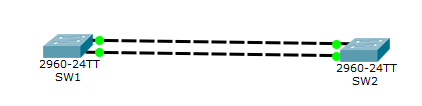
All links are green and active. STP does not work for them.
I'll warn you right away that there is a glitch in the packet tracer. The bottom line is that after setting up the interfaces can go to stand-alone (parameter I) and will not want to leave it in any way. At the time of this writing, I had this glitch and decided to re-create labs.
Now we delve a little into the work of LACP. Turn on the simulation mode and select only the LACP filter, so that the others do not distract.
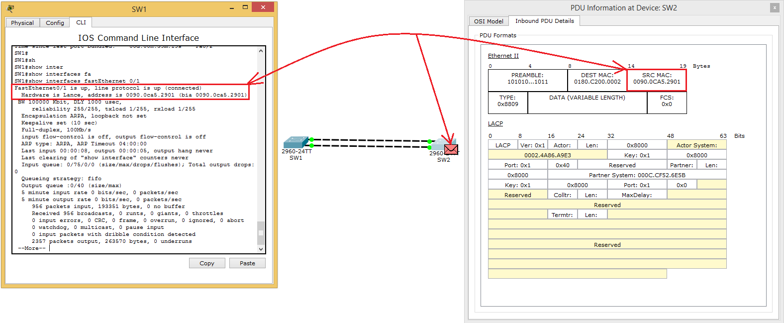
See that SW1 sends a LACP message to the neighbor. We look at the Ethernet field. In the Source, it records its MAC address, and in the Destination the multicast address is 0180.C200.0002. This address is listening to the LACP protocol. Well and above is the "long footcloth" from LACP. I will not dwell on each field, but only note those that, in my opinion, are important. But before that, a few words. This message is used by devices for many purposes. This is synchronization, collection, aggregation, activity check, and so on. That is, it has several functions. And before this all starts working, they choose a virtual MAC address for themselves. This is usually the smallest available.
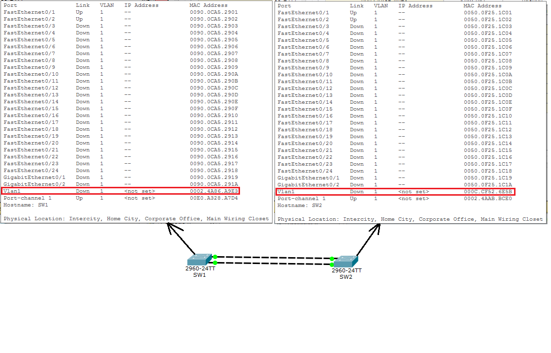
And they will write these addresses in the LACP fields.
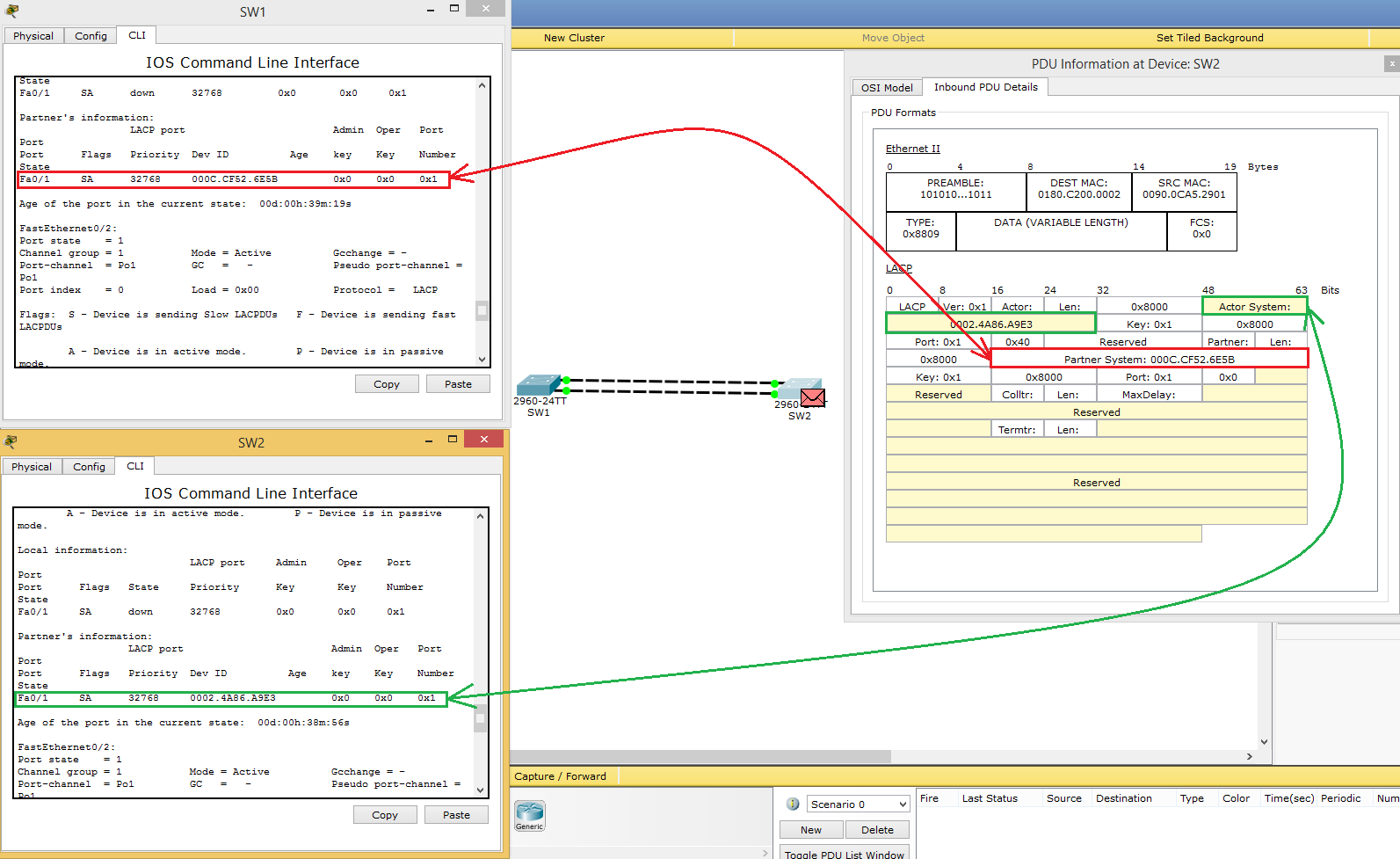
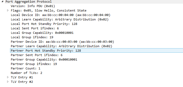
On the move, it may not immediately go to the head. I think it will be easier to lay down with pictures. In CPT, the LACP format is a bit crooked, so I’ll provide a screen for a real dump.
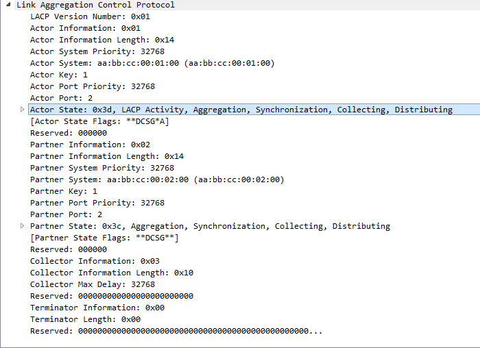
The highlighted line shows for exactly what purpose the message was sent. That is the essence of his work. Now it’s a single logical port-channel interface. You can go to him and make sure:
SW1(config)#interface port-channel 1 SW1(config-if)#? arp Set arp type (arpa, probe, snap) or timeout bandwidth Set bandwidth informational parameter cdp Global CDP configuration subcommands delay Specify interface throughput delay description Interface specific description duplex Configure duplex operation. exit Exit from interface configuration mode hold-queue Set hold queue depth no Negate a command or set its defaults service-policy Configure QoS Service Policy shutdown Shutdown the selected interface spanning-tree Spanning Tree Subsystem speed Configure speed operation. storm-control storm configuration switchport Set switching mode characteristics tx-ring-limit Configure PA level transmit ring limit And all actions performed on this interface will automatically lead to changes on the physical ports. Here is an example:
SW1(config-if)#switchport mode trunk %LINEPROTO-5-UPDOWN: Line protocol on Interface Port-channel 1, changed state to down %LINEPROTO-5-UPDOWN: Line protocol on Interface Port-channel 1, changed state to up %LINEPROTO-5-UPDOWN: Line protocol on Interface FastEthernet0/1, changed state to down %LINEPROTO-5-UPDOWN: Line protocol on Interface FastEthernet0/1, changed state to up %LINEPROTO-5-UPDOWN: Line protocol on Interface FastEthernet0/2, changed state to down %LINEPROTO-5-UPDOWN: Line protocol on Interface FastEthernet0/2, changed state to up As soon as the port-channel was switched to trunk mode, it automatically pulled the physical interfaces behind it. We type show running-config :
SW1#show running-config Building configuration... Current configuration : 1254 bytes ! version 12.2 no service timestamps log datetime msec no service timestamps debug datetime msec no service password-encryption ! hostname SW1 ! ! ! ! ! spanning-tree mode pvst ! interface FastEthernet0/1 channel-group 1 mode active switchport mode trunk ! interface FastEthernet0/2 channel-group 1 mode active switchport mode trunk ! *************************************** interface Port-channel 1 switchport mode trunk ! And indeed it is.
Now I’ll tell you about such a technology that deserves special attention, like Load-Balance or in Russian “balancing”. When creating an aggregated channel, one should not forget that within it the physical interfaces and they let traffic through. There are cases that the channel seems to be aggregated, everything works, but there is a situation that all traffic goes through one interface and the rest are idle. As it happens I will explain on a usual example. Let's see how Load-Balance works in the current lab.
SW1#show etherchannel load-balance EtherChannel Load-Balancing Operational State (src-mac): Non-IP: Source MAC address IPv4: Source MAC address IPv6: Source MAC address At the moment, it performs balancing based on the value of the MAC address. By default, balancing is done this way. That is, it will pass the 1st MAC address through the first link, the 2nd MAC address through the second link, the 3rd MAC address again through the first link and will alternate. But this approach is not always true. Explain why.
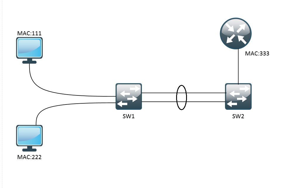
There is some kind of conditional network. 2 computers are connected to SW1. Next, this switch connects to the SW2 aggregated channel. And the router is connected to SW2. By default, Load-Balance is configured for src-mac. And that's what will happen. Frames with MAC address 111 will be transmitted on the first link, and with MAC address 222 on the second link. Right here. Go to SW2. Only one router with MAC address 333 is connected to it. And all the frames from the router will be sent to SW1 via the first link. Accordingly, the second will always be idle. Therefore, it is more logical to set up balancing here not by the Source MAC address, but by the Destination MAC address. Then, for example, everything that is sent to the 1st computer will be sent on the first link, and the second on the second link.
This is a very simple example, but it reflects the essence of this technology. It changes as follows:
SW1(config)#port-channel load-balance ? dst-ip Dst IP Addr dst-mac Dst Mac Addr src-dst-ip Src XOR Dst IP Addr src-dst-mac Src XOR Dst Mac Addr src-ip Src IP Addr src-mac Src Mac Addr I think this is understandable. I note that this is an example of balancing not only for LACP, but also for other methods.
I finish the conversation about LACP. Finally, I can only say that this protocol is used most often due to its openness and can be used on most vendors.
Those who thought it was not enough can get LACP here , here and here . And in addition, a link to this lab.
Now about a colleague PAgP. As mentioned above, this is a purely “tsiskovsky” protocol. It is used less frequently (as there are fewer networks built exclusively on Cisco equipment than heterogeneous). It works and is configured similarly to LACP, but Cisco requires it to be known and proceed to the review.
PAgP also has 2 modes:
- Desirable - includes PAgP.
- Auto - turn on if a PAgP message arrives.
| Mode | Desirable | Auto |
|---|---|---|
| Desirable | Yes | Yes |
| Auto | Yes | Not |
We assemble a similar lab.
And go to SW1:
SW1(config)#interface range fastEthernet 0/1-2 - . SW1(config)#shutdown - . %LINK-5-CHANGED: Interface FastEthernet0/1, changed state to administratively down %LINEPROTO-5-UPDOWN: Line protocol on Interface FastEthernet0/1, changed state to down %LINK-5-CHANGED: Interface FastEthernet0/2, changed state to administratively down %LINEPROTO-5-UPDOWN: Line protocol on Interface FastEthernet0/2, changed state to down SW1(config-if-range)#channel-group 1 mode desirable - port-channel desirable ( ). Creating a port-channel interface Port-channel 1 Now we are going to configure SW2 (do not forget that the interfaces are turned off on SW1 and should be returned after them):
SW2(config)#interface range fastEthernet 0/1-2 - . SW2(config-if-range)#channel-group 1 mode auto - port-channel auto (, PAgP-). Creating a port-channel interface Port-channel 1 Go back to SW1 and enable the interfaces:
SW1(config)#interface range fastEthernet 0/1-2 SW1(config-if-range)#no shutdown %LINK-5-CHANGED: Interface FastEthernet0/1, changed state to up %LINEPROTO-5-UPDOWN: Line protocol on Interface FastEthernet0/1, changed state to up %LINK-5-CHANGED: Interface Port-channel 1, changed state to up %LINEPROTO-5-UPDOWN: Line protocol on Interface Port-channel 1, changed state to up %LINK-5-CHANGED: Interface FastEthernet0/2, changed state to up %LINEPROTO-5-UPDOWN: Line protocol on Interface FastEthernet0/2, changed state to up . . SW1: <source>SW1#show etherchannel summary Flags: D - down P - in port-channel I - stand-alone s - suspended H - Hot-standby (LACP only) R - Layer3 S - Layer2 U - in use f - failed to allocate aggregator u - unsuitable for bundling w - waiting to be aggregated d - default port Number of channel-groups in use: 1 Number of aggregators: 1 Group Port-channel Protocol Ports ------+-------------+-----------+---------------------------------------------- 1 Po1(SU) PAgP Fa0/1(P) Fa0/2(P) SW2:
SW2#show etherchannel summary Flags: D - down P - in port-channel I - stand-alone s - suspended H - Hot-standby (LACP only) R - Layer3 S - Layer2 U - in use f - failed to allocate aggregator u - unsuitable for bundling w - waiting to be aggregated d - default port Number of channel-groups in use: 1 Number of aggregators: 1 Group Port-channel Protocol Ports ------+-------------+-----------+---------------------------------------------- 1 Po1(SU) PAgP Fa0/1(P) Fa0/2(P) Now go to the simulation and tune in to the PAgP filter. We see, the departing message from SW2. We look.
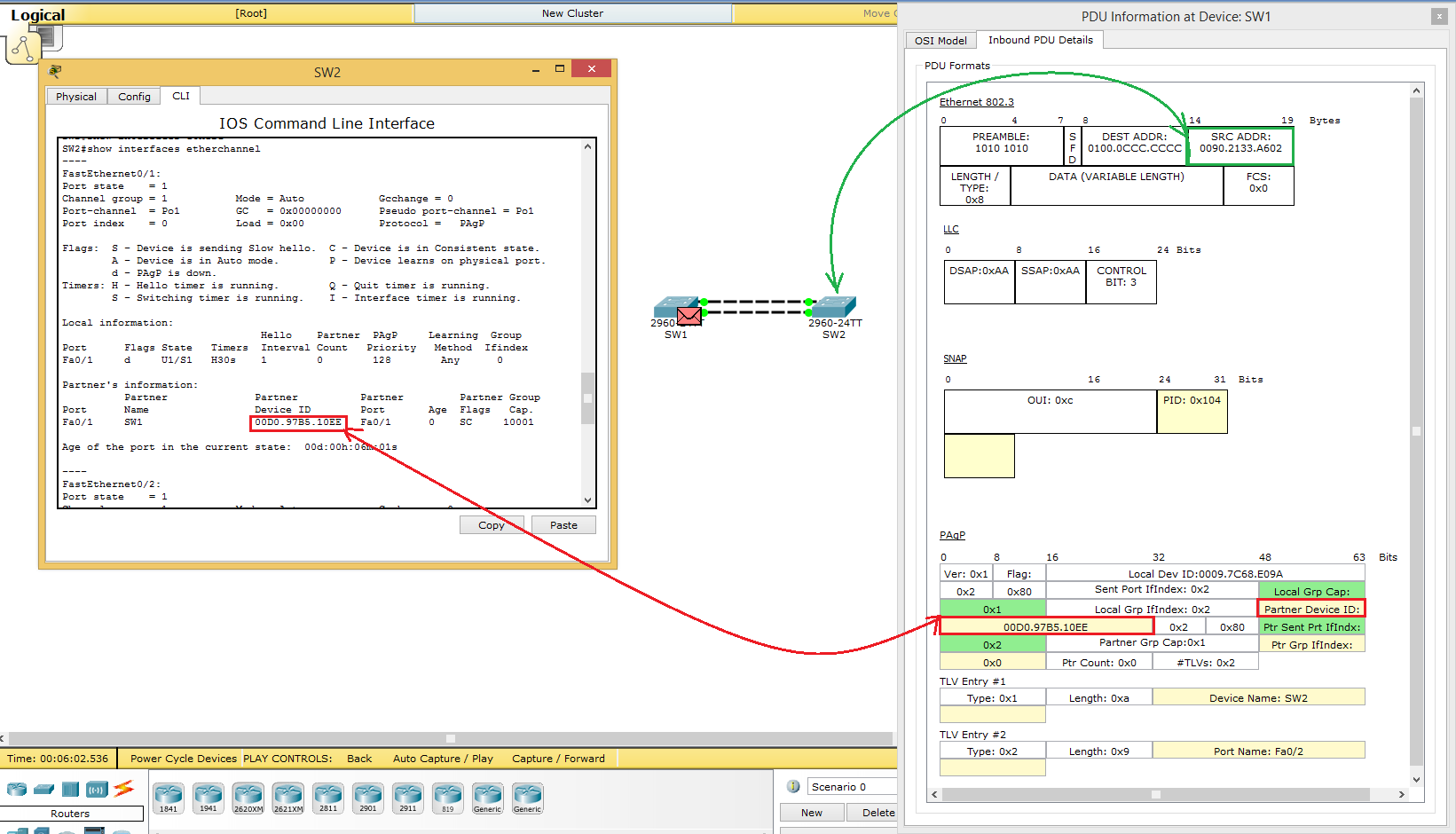
That is, we see in the Source MAC address SW2. In Destination multicast address for PAgP. Higher protocols LLC and SNAP. They do not interest us in this case and go to PAgP. In one of the fields, he writes the virtual MAC address of SW1 (he is chosen according to the same principle as in LACP), and below he writes his name and the port from which this message came out.
In principle, there are practically no differences from LACP, except for the structure itself. Who wants to read more, link to the laboratory. And this is how it looks real:
The last thing left is manual aggregation. Everything is simple with aggregation:
| Mode | On |
|---|---|
| On | Yes |
With other settings, the channel will not work.
As mentioned above, there is no additional protocol negotiation, verification. Therefore, before aggregation, you need to verify the identity of the interface settings. Or reset the interface settings with the command:
Switch(config)#default interface faX/X In the lab, everything is created by default. Therefore, I turn immediately to the settings.
SW1(config)#interface range fastEthernet 0/1-2 SW1(config-if-range)#shutdown %LINK-5-CHANGED: Interface FastEthernet0/1, changed state to administratively down %LINEPROTO-5-UPDOWN: Line protocol on Interface FastEthernet0/1, changed state to down %LINK-5-CHANGED: Interface FastEthernet0/2, changed state to administratively down %LINEPROTO-5-UPDOWN: Line protocol on Interface FastEthernet0/2, changed state to down SW1(config-if-range)#channel-group 1 mode on - port-channel . Creating a port-channel interface Port-channel 1 SW1(config-if-range)#no shutdown %LINK-5-CHANGED: Interface FastEthernet0/1, changed state to up %LINEPROTO-5-UPDOWN: Line protocol on Interface FastEthernet0/1, changed state to up %LINK-5-CHANGED: Interface Port-channel 1, changed state to up %LINEPROTO-5-UPDOWN: Line protocol on Interface Port-channel 1, changed state to up %LINK-5-CHANGED: Interface FastEthernet0/2, changed state to up %LINEPROTO-5-UPDOWN: Line protocol on Interface FastEthernet0/2, changed state to up And similarly on SW2:
SW2(config)#interface range fastEthernet 0/1-2 SW2(config-if-range)#channel-group 1 mode on Creating a port-channel interface Port-channel 1 %LINK-5-CHANGED: Interface Port-channel 1, changed state to up %LINEPROTO-5-UPDOWN: Line protocol on Interface Port-channel 1, changed state to up %LINEPROTO-5-UPDOWN: Line protocol on Interface FastEthernet0/1, changed state to down %LINEPROTO-5-UPDOWN: Line protocol on Interface FastEthernet0/1, changed state to up %LINEPROTO-5-UPDOWN: Line protocol on Interface FastEthernet0/2, changed state to down %LINEPROTO-5-UPDOWN: Line protocol on Interface FastEthernet0/2, changed state to up Setup is complete. Check with the show etherchannel summary command:
SW1#show etherchannel summary Flags: D - down P - in port-channel I - stand-alone s - suspended H - Hot-standby (LACP only) R - Layer3 S - Layer2 U - in use f - failed to allocate aggregator u - unsuitable for bundling w - waiting to be aggregated d - default port Number of channel-groups in use: 1 Number of aggregators: 1 Group Port-channel Protocol Ports ------+-------------+-----------+---------------------------------------------- 1 Po1(SU) - Fa0/1(P) Fa0/2(P) Ports with the necessary parameters, and in the field protocol "-". That is, in addition, nothing is used.
As you can see all the methods of setting up the aggregation do not cause any difficulties and differ only in a couple of commands.
By the end of the article I will quote a small Best Practice on correct aggregation. All labs used 2 cables for aggregation. In fact, you can use 3 and 4 (up to 8 interfaces in a single port-channel). But it is better to use 2, 4 or 8 interfaces. And all because of the hashing algorithm that Cisco came up with. The algorithm calculates hash values from 0 to 7.
| four | 2 | one | Decimal value |
|---|---|---|---|
| 0 | 0 | 0 | 0 |
| 0 | 0 | one | one |
| 0 | one | one | 3 |
| one | 0 | 0 | four |
| 0 | 0 | one | one |
| one | 0 | one | five |
| one | one | 0 | 6 |
| one | one | one | 7 |
This table displays 8 values in binary and decimal form.
Based on this value, an Etherchannel port is selected and assigned a value. After that, the port receives a certain “mask” that displays the values for which that port is responsible. Here is an example. We have 2 physical interfaces, which we combine into one port-channel.
Values are spread out as follows:
1) 0x0 - fa0 / 1
2) 0x1 - fa0 / 2
3) 0x2 - fa0 / 1
4) 0x3 - fa0 / 2
5) 0x4 - fa0 / 1
6) 0x5 - fa0 / 2
7) 0x6 - fa0 / 1
8) 0x7 - fa0 / 2
As a result, we get that half of the values or patterns will be taken by fa0 / 1, and the second half by fa0 / 2. That is, we get 4: 4. In this case, balancing will work correctly (50/50).
Now let's move on and explain why it is not recommended to use, for example, 3 interfaces. We make a similar comparison:
1) 0x0 - fa0 / 1
2) 0x1 - fa0 / 2
3) 0x2 - fa0 / 3
4) 0x3 - fa0 / 1
5) 0x4 - fa0 / 2
6) 0x5 - fa0 / 3
7) 0x6 - fa0 / 1
8) 0x7 - fa0 / 2
Here we get that fa0 / 1 will take on 3 patterns, fa0 / 2 also 3 patterns, and fa0 / 3 2 patterns. Accordingly, the load will not be evenly distributed. We get 3: 3: 2. That is, the first two links will always be more loaded than the third.
I will not consider all other options, as the article will stretch to even more characters. One can only estimate that if we have 8 values and 8 links, then each link will take for itself a pattern and it will turn out 1: 1: 1: 1: 1: 1: 1: 1. This means that all interfaces will be loaded in the same way. There is still some claim that you only need to aggregate an even number of wires in order to achieve proper balancing. But this is not entirely true. For example, if you combine 6 wires, then balancing will not be uniform. Try to find yourself. I hope the algorithm is clear.
Cisco on the site in this case has a good article with a sign. You can read on this link . If you still have questions, write!
Since I’ve been so deep, I’ll tell you about the increase in throughput. I specifically touched on this topic at the end. There are cases that urgently need to increase the bandwidth. There is no money for equipment, but there are free ports that can be collected and put into one “thick” stream. Many sources (books, forums, websites) say that connecting eight 100-megabit ports, we get a stream of 800 Mb / s or eight gigabit ports will give 8 Gb / s. Here is a piece of text from the "ciskovskaya" article .
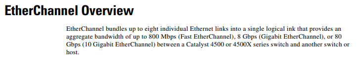
Theoretically, this is possible, but in practice it is almost unattainable. I at least have not met. If there are people who were able to achieve this, I will be glad to hear. That is, to get it, you need to take into account a bunch of formalities. And those that I described, only part. This does not mean that there will be no increase at all. It certainly will, but not as much as possible.
This article has come to an end. In this article, we learned how to aggregate channels manually, as well as using LACP and PAgP protocols. We learned what balancing is, how it can be controlled and how to properly assemble the Etherchannel to obtain the maximum load distribution. See you in the next article!
Source: https://habr.com/ru/post/334778/
All Articles