Create your own software 3D-engine
Part 1: points, vectors and basic principles
Modern three-dimensional game engines used in major projects are a subtle blend of mathematics and programming. Many game programmers admit that it’s very difficult to fully understand them. If you lack experience (or professional education, like me), this task becomes even more difficult. I want to introduce you to the basics of graphics systems 3D-engines.
In this part we will look at the points and vectors, as well as all the interesting things related to them. If you own the basics of algebra (variables and mathematics of variables) and computer science (the basics of any object-oriented language), then you can understand this article. But remember, some of the topics will be quite complex.
Basic coordinate systems
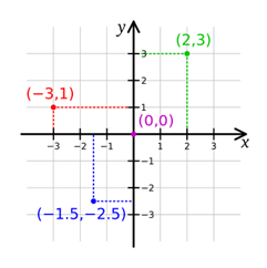
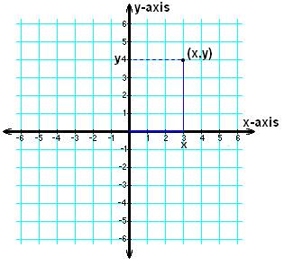
Let's start with the basics. Three-dimensional graphics require the concept of three-dimensional space. Of all the types of spaces, the Cartesian space is most often used, which allows us to apply Cartesian coordinates (standard entry ( x , y ) and two-dimensional graphics, which are studied in most schools).
A curse to poison many schoolchildren
')
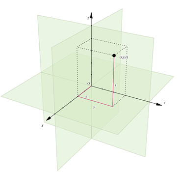
Three-dimensional Cartesian space gives us the axes x, y and z (describing the position of the horizontal, vertical and depth). The coordinates of any point in this space are designated as several numbers (in our case there are three numbers, because we have three axes). On a two-dimensional plane, an entry is denoted as ( x , y ) , and in three-dimensional space - as ( x , y , z ) . This record ( tuple ) shows the position of a point relative to the original point of space (which is usually denoted as ( 0 , 0 , 0 ) .
Hint: A tuple is an ordered list (or sequence) of elements in computer science or mathematics. That is a record ( K , y , l , e ) will be a four-element tuple showing the sequence of characters that make up my name.
In this space we will define a point as a tuple of three elements. This can be denoted as:
P = ( x , y , z )
In addition to setting the point, we need to define its parts.
Each of the elements of a tuple is a scalar number that determines the position along the base vector . Each basic vector must have a unit length (its length is 1), that is, such tuples as ( 1 , 1 , 1 ) and ( 2 , 2 , 2 ) cannot be basic vectors because they are too long.
We define three basic vectors in our space:
\ begin {aligned} X & = (1,0,0) \\ Y & = (0,1,0) \\ Z & = (0,0,1) \ end {aligned}
Source: http://www.thefullwiki.org/Arithmetics/Cartesian_Coordinate.
Coordinate system
Now let's talk about the mathematical definition of our coordinate system, how it affects the graphics system and the calculations that we can make.
Point designation
The origin of the coordinate system can be denoted by a point O , which is described by a tuple of three elements (0,0,0). This means that the mathematical representation of the coordinate system can be represented as follows:
\ {O; X, Y, Z \}
With this record we can say that (x,y,z) represent the position of the point relative to the origin. Such a definition means that any point P , (a,b,c) can be represented as:
P=O+aX+bY+cZ
From now on, we will denote scalar values in lower case letters, and vectors - in upper case, that is, a , b and c - these are scalars, and X , Y and Z - vectors. (Actually, these are basic vectors, which we defined above.)
This means that the point recorded by the tuple (2,3,4) can be represented as follows:
\ begin {aligned} (2,3,4) & = (2,0,0) + (0,3,0) + (0,0,4) \\ & = (0,0,0) + (2.0.0) + (0.3.0) + (0.0.4) \\ = (0.0.0) + 2 (1.0.0) + 3 (0.1, 0) + 4 (0,0,1) \\ & = O + 2X + 3Y + 4Z \\ end {aligned}
So, we took the abstract concept of "a point in three-dimensional space" and defined it as the sum of four objects. Such a definition will be very important when it comes to the implementation of the concept in code.
Mutual perpendicularity
The coordinate system, which we will use, has a very valuable property: mutual perpendicularity . This means that at the intersection of each of the axes on its respective plane, the angle between them is 90 degrees.
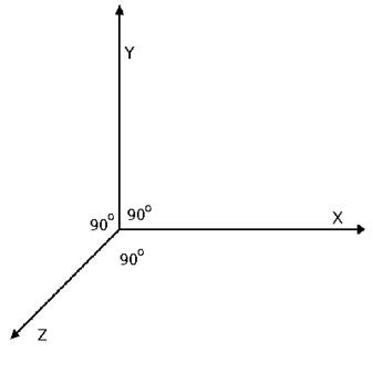
Our coordinate system can also be called "right":

Source: http://viz.aset.psu.edu/gho/sem_notes/3d_fundamentals/html/3d_coordinates.html .
In the language of mathematics, this means that:
X=Y timesZ
Where times denotes the vector product operator.
A vector product can be defined by the following equation (provided that we have two tuples of three elements):
(a,b,c) times(d,e,f)=(bf−ce,cd−af,ae−bd)
These expressions may seem boring, but later they will allow us to more easily perform many different calculations and transformations. Fortunately, when creating a game engine, we do not need to memorize all these equations - we can start with these expressions and then build on less complex systems over them. At least, until you want to change something fundamental in the engine!
Points and Vectors
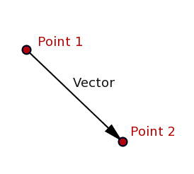
Having defined the basics of the coordinate system, we can talk about points and vectors, and, more importantly, how they interact with each other. First, it is worth noting that points and vectors are completely different objects: a point is a physical place in space, a vector is a space between two points.
In order not to confuse these two types of objects, I will write points in italic capital letters, for example, P and vectors are in bold capital letters, for example, mathbfV .
When working with points and vectors, we will use two basic axioms. Here they are:
- Axiom 1: the difference between two points is a vector, that is mathbfV=P−Q
- Axiom 2: the sum of a point and a vector is a point, that is Q=P+ mathbfV
Hint: an axiom is a logical statement, considered obvious enough to be accepted without evidence.
Create engine
Thanks to these two axioms, we have enough information to create classes of "bricks" that are the heart of any three-dimensional game engine: the
Point class and the Vector class. If we were going to create our own engine based on this information, we would need to take other important steps in creating these classes (mainly related to optimizing and working with existing APIs), but we will omit this for the sake of simplification.All class examples will be written in pseudocode so that you can implement them in your favorite language. Here are the sketches of our two classes:
Point Class { Variables: num tuple[3]; //(x,y,z) Operators: Point AddVectorToPoint(Vector); Point SubtractVectorFromPoint(Vector); Vector SubtractPointFromPoint(Point); Function: // API, // drawPoint; } Vector Class { Variables: num tuple[3]; //(x,y,z) Operators: Vector AddVectorToVector(Vector); Vector SubtractVectorFromVector(Vector); } As an exercise, try filling out each of the functions of these classes with working code (based on what we have discussed above). When finished with this, test the work by running this simple program:
main { var point1 = new Point(1,2,1); var point2 = new Point(0,4,4); var vector1 = new Vector(2,0,0); var vector2; point1.drawPoint(); // (1,2,1) point2.drawPoint(); // (0,4,4) vector2 = point1.subtractPointFromPoint(point2); vector1 = vector1.addVectorToVector(vector2); point1.addVectorToPoint(vector1); point1.drawPoint(); // (4,0,-2) point2.subtractVectorFromPoint(vector2); point2.drawPoint(); // (-1,6,7) } Conclusion
We got to the end of the first part! It seems that a bunch of mathematics is used here just to write two classes, and this is actually the case. In most cases, you will never have to work with the game at this level, but knowing the details of the internal workings of the game engine will still be useful (at least for your own pleasure).
Part 2: Linear Transformations
Now we will talk about linear transformations , which will allow us to change such properties of vectors as rotation and scale. We will learn how to apply them in the classes we have already created.
To discuss linear transformations, we need to make a small change to the Point class: instead of outputting data to the console, use any graphics API that is convenient for you so that the function draws the current point on the screen.
Basics of linear transformations
Just a warning: the equations of linear transformations always look much more complicated than they actually are. We will use trigonometry, but you don’t really need to know how trigonometric operations are performed: I will explain what you need to transfer to each function and what we will receive from it, and you can use any calculator or mathematical library for all intermediate actions.
Hint: if you want to get deeper into the inner workings of these equations, then you should watch this video and read this PDF .
All linear transformations have the following form:
B=f(a)
From this it is clear that we have a conversion function F() , vector is used as input A , and at the output we get a vector B .
Each of these parts — two vectors and a function — can be represented as a matrix: a vector B - as a 1x3 matrix, vector A - as one more matrix 1x3, and linear transformation F() - as a 3x3 matrix ( transformation matrix ).
This means that by expanding the equation, we get the following:
\ begin {bmatrix} b_ {0} \\ b_ {1} \\ b_ {2} \ end {bmatrix} = \ begin {bmatrix} f_ {00} & f_ {01} & f_ {02} \\ f_ {10} & f_ {11} & f_ {12} \\ f_ {20} & f_ {21} & f_ {22} \ end {bmatrix} \ begin {bmatrix} a_ {0} \\ a_ {1} \ \ a_ {2} \ end {bmatrix}
If you have gone through trigonometry or linear algebra, then you may already recall the nightmare of mathematics of matrices. Fortunately, there is an easier way to write this expression to get rid of most problems. It looks like this:
beginbmatrixb0b1b2 endbmatrix= beginbmatrixf00a0+f01a1+f02a2f10a0+f11a1+f12a2f20a0+f21a1+f22a2 endbmatrix
However, these equations can change when there is a second source of input data, as in the case of rotations, when the vector and the number of its rotation must be specified. Let's see how the turns work.
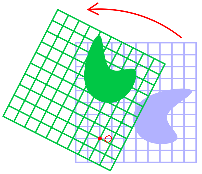
Turns
A turn, by definition, is a circular motion of an object around a turning point. The turning point in our space can belong to the XY plane, the XZ plane, or the YZ plane (where each plane is composed of two basis vectors, which we discussed in the first part).
Three turning points mean that we have three separate rotation matrices:
XY rotation matrix:
\ begin {bmatrix} cos \ theta & -sin \ theta & 0 \\ sin \ theta & cos \ theta & 0 \\ 0 & 0 & 1 \\ \ end {bmatrix}
XZ rotation matrix:
\ begin {bmatrix} cos \ theta & 0 & sin \ theta \\ 0 & 1 & 0 \\ -sin \ theta & 0 & cos \ theta \ end {bmatrix}
YZ rotation matrix:
\ begin {bmatrix} 1 & 0 & 0 \\ 0 & cos \ theta & -sin \ theta \\ 0 & sin \ theta & cos \ theta \ end {bmatrix}
That is to rotate the point A around the XY plane by 90 degrees ( pi/2 radian - most math libraries have a function to convert degrees to radians), you need to do the following:
\ begin {aligned} \ begin {bmatrix} b_ {0} \\ b_ {1} \\ b_ {2} \ end {bmatrix} & = \ begin {bmatrix} cos \ frac {\ pi} {2} & -sin \ frac {\ pi} {2} & 0 \\ sin \ frac {\ pi} {2} & cos \ frac {\ pi} {2} & 0 \\ 0 & 0 & 1 \ end {bmatrix} \ begin {bmatrix} a_ {0} \\ a_ {1} \\ a_ {2} \ end {bmatrix} \\ & = \ begin {bmatrix} cos \ frac {\ pi} {2} a_ {0} + -sin \ frac {\ pi} {2} a_ {1} + 0a_ {2} \\ sin \ frac {\ pi} {2} a_ {0} + cos \ frac {\ pi} {2} a_ {1 } + 0a_ {2} \\ 0a_ {0} + 0a_ {1} + 1a_ {2} \ end {bmatrix} \\ & = \ begin {bmatrix} 0a_ {0} + -1a_ {1} + 0a_ {2 } \\ 1a_ {0} + 0a_ {1} + 0a_ {2} \\ 0a_ {0} + 0a_ {1} + 1a_ {2} \ end {bmatrix} \\ & = \ begin {bmatrix} -a_ { 1} \\ a_ {0} \\ a_ {2} \ end {bmatrix} \ end {aligned}
That is, if the starting point A had coordinates (3,4,5) then the exit point B will have coordinates (−4,3,5) .
Exercise: turning functions
As an exercise, try creating three new functions for the
Vector class. One must rotate the vector around the XY plane, the other around YZ, and the third around XZ. At the input, the functions should receive the required number of degrees of rotation, and return the vector at the output.In general, the functions should work as follows:
- Create output vector.
- Convert the input in degrees to radians.
- The solution of each of the elements of the output vector tuple using the above equations.
- Return the output vector.
Scaling
Scaling is a transformation that enlarges or reduces an object according to a given scale.
This transformation is quite simple (at least compared to turns). Scaling transformation requires two types of input data: an input vector and a three-element scaling tuple , which defines the scale of the input vector along each axis of space.
For example, in a scaling tuple (s0,s1,s2) magnitude s0 is the X scale, s1 - along the Y axis, and s2 - along the Z axis.
The scale transformation matrix has the following form (where s0 , s1 and s2 - these are elements of the scaling tuple):
\ begin {bmatrix} s0 & 0 & 0 \\ 0 & s1 & 0 \\ 0 & 0 & s2 \ end {bmatrix}
To make an input vector A (a0,a1,a2) twice the X axis (i.e. use a tuple S=(2,1,1) ), the calculations should be as follows:
\ begin {aligned} \ begin {bmatrix} b_ {0} \\ b_ {1} \\ b_ {2} \ end {bmatrix} & = \ begin {bmatrix} s0 & 0 & 0 \\ 0 & s1 & 0 \\ 0 & 0 & s2 \ end {bmatrix} \ begin {bmatrix} a_ {0} \\ a_ {1} \\ a_ {2} \ end {bmatrix} \\ & = \ begin {bmatrix} 2 & 0 & 0 \\ 0 & 1 & 0 \\ 0 & 0 & 1 \ end {bmatrix} \ begin {bmatrix} a_ {0} \\ a_ {1} \\ a_ {2} \ end {bmatrix} \\ & = \ begin {bmatrix} 2a_ {0} + 0a_ {1} + 0a_ {2} \\ 0a_ {0} + 1a_ {1} + 0a_ {2} \\ 0a_ {0} + 0a_ {1} + 1a_ {2} \ end {bmatrix} \\ & = \ begin {bmatrix} 2a_ {0} \\ a_ {1} \\ a_ {2} \ end {bmatrix} \ end {aligned}
That is, when the input vector A=(3,4,0) output vector B will be equal to (6,4,0) .
Exercise: Scaling Functions
As another exercise, add a new feature to the Vector class. This new function should receive a scaling tuple and return the output vector.
In general, the function should work as follows:
- Create output vector.
- The solution of each element of the output vector tuple using the above equation (which can be simplified to
y0 = x0 * s0; y1 = x1*s1; y2 = x2*s2). - Return the output vector.
Let's create something!
Now that we have linear transformations at our disposal, let's create a small program to demonstrate the new features. We will create a program that draws a group of points on the screen and allows you to change them as a whole, performing linear transformations over them.
Before we begin, we need to add another function to the
Point class. We will call it setPointToPoint() , it will simply set the position of the current point at the point that is passed to it. At the entrance she will receive a point and not return anything.Here are the brief characteristics of the program:
- The program will store in an array of 100 points.
- When you press the D key, the program will clear the current screen and redraw the points.
- When you press the A key, the program will scale the position of all points by 0.5.
- When you press the S key, the program will scale the position of all points by 2.0.
- Pressing the R key will rotate the position of all points by 15 degrees on the XY plane.
- When you press the Escape key, the program closes (if you do not write it in JavaScript or another web-oriented language).
The classes we have are:
Point Class { Variables: num tuple[3]; //(x,y,z) Operators: Point AddVectorToPoint(Vector); Point SubtractVectorFromPoint(Vector); Vector SubtractPointFromPoint(Point); // Null SetPointToPoint(Point); Functions: // API drawPoint; } Vector Class { Variables: num tuple[3]; //(x,y,z) Operators: Vector AddVectorToVector(Vector); Vector SubtractVectorFromVector(Vector); Vector RotateXY(degrees); Vector RotateYZ(degrees); Vector RotateXZ(degrees); Vector Scale(s0,s1,s2); } Let's see what the code might look like given the above requirements:
main{ // API // ( ) // 100 Point Array pointArray[100]; for (int x = 0; x < pointArray.length; x++) { // pointArray[x].tuple = [random(0,screenWidth), random(0,screenHeight), random(0,desiredDepth)); } // function redrawScreen() { // API ClearTheScreen(); for (int x = 0; x < pointArray.length; x++) { // pointArray[x].drawPoint(); } } // escape, while (esc != pressed) { // if (key('d') == pressed) { redrawScreen(); } if (key('a') == pressed) { // Point origin = new Point(0,0,0); Vector tempVector; for (int x = 0; x < pointArray.length; x++) { // tempVector = pointArray[x].subtractPointFromPoint(origin); // , pointArray[x].setPointToPoint(origin); // pointArray[x].addVectorToPoint(tempVector.scale(0.5,0.5,0.5)); } redrawScreen(); } if(key('s') == pressed) { // Point origin = new Point(0,0,0); Vector tempVector; for (int x = 0; x < pointArray.length; x++) { // tempVector = pointArray[x].subtractPointFromPoint(origin); // , pointArray[x].setPointToPoint(origin); // pointArray[x].addVectorToPoint(tempVector.scale(2.0,2.0,2.0)); } redrawScreen(); } if(key('r') == pressed) { // Point origin = new Point(0,0,0); Vector tempVector; for (int x = 0; x < pointArray.length; x++) { // tempVector = pointArray[x].subtractPointFromPoint(origin); // , pointArray[x].setPointToPoint(origin); // pointArray[x].addVectorToPoint(tempVector.rotateXY(15)); } redrawScreen(); } } } So, we have a short, good program that demonstrates all our new features!
Conclusion
Although we have not considered all possible linear transformations, our micromotor begins to take shape.
As usual, for simplicity, I removed some things from the engine (namely, displacement and reflections). If you want to learn more about these two types of linear transformations, then you can read in the Wikipedia article and the links in the article.
In the next section, we will look at the various viewing spaces and the clipping of objects that are out of scope.
Part 3: Space and Clipping
It can be seen that for the time being the use of the two classes created by us in themselves is a rather complicated process, besides drawing each possible point can quite quickly drain the system memory. To solve these problems, we will add a new class to the game engine: a camera .
Rendering will occur only within the camera, it cuts all objects to the size of the screen, and also controls all of our points.
But before we begin all this, we must first talk about clipping.
Clipping
By definition, pruning is a selection of objects from a larger group of objects. In our game engine a smaller group will be points that need to be drawn on the screen. A larger group of objects will be the set of all existing points.
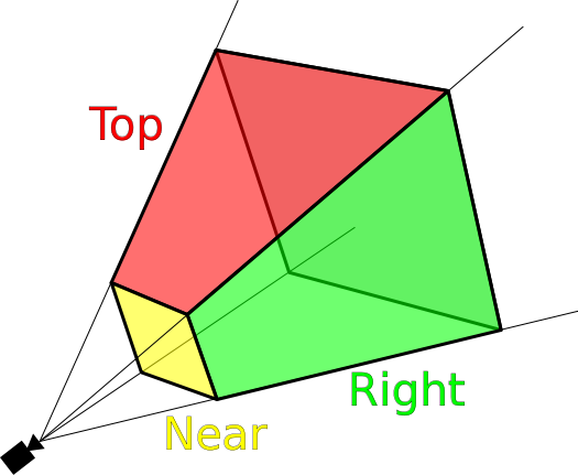
Thanks to the cut-off engine, the system memory consumption will be significantly reduced. It will only draw what the player can see, and not the whole world of points. In our engine, we implement this by setting the parameters of the viewing space .
The overview space will be set along all three of our traditional axes: x, y and z. Its borders in x consist of everything between the left and right borders of the window, the borders in y are from everything between the upper and lower borders of the window, and the borders in z are in the range from
0 (where the camera is installed) will use a randomly selected value of 100 ).Before drawing a point, the camera class will check if the point is in view space. If it is, then the point is drawn; otherwise, it is not drawn.
Maybe it's time to add a camera?
By understanding the basics of clipping, we can create a camera class:
Camera Class { Vars: int minX, maxX; // X int minY, maxY; //. . Y int minZ, maxZ; //. . Z } We will also put on camera the whole process of rendering in the engine. Often in renderers engines are separated from camera systems. This is usually done for the convenience of encapsulating systems, because in some engines, when they are stored together, there is confusion. However, it will be easier for our tutorial to treat them as a single system.
First we need a function that can be called from the outside of the class to draw the scene. This function will cycle through all existing points, compare them with the clipping parameters of the camera and draw them if conditions are met.
Source: http://en.wikipedia.org/wiki/File:ViewFrustum.svg
Hint: if you want to separate the camera system from the renderer, you can simply create the
Renderer class, cut the points by the camera system, save the ones you want to draw in the array, and then send the array to the renderer’s draw() function.Point management
The last part of the camera class will be the point control system. Depending on the programming language used, this may simply be an array of all objects for drawing (later we will not only process points), or it may be necessary to use the parent class of objects by default. If you are very unlucky with the choice, then you have to implement your own parent class of objects and make sure that all the classes being rendered (as long as these are only points) inherit from this class.
After adding a control system to a class, our camera will look something like this:
Camera Class { Vars: int minX, maxX; // X int minY, maxY; // Y int minZ, maxZ; // Z array objectsInWorld; // Functions: null drawScene(); // , } Having made all these additions, let's improve a little the program written in the last part.
Bigger and better
We are going to create a simple point drawing program based on the example program created in the last part.
In this iteration of the program we will add the use of a new camera class. When you press the D key, the program will redraw the screen without clipping, showing the number of rendered objects in the upper right corner of the screen. When you press the C key, the program will redraw the screen with clipping, also showing the number of rendered objects.
Let's take a look at the code:
main{ // API // ( ) var camera = new Camera(); // camera.objectsInWorld[100]; // 100 // camera.minX = 0; camera.maxX = screenWidth; camera.minY = 0; camera.maxY = screenHeight; camera.minZ = 0; camera.maxZ = 100; for(int x = 0; x < camera.objectsInWorld.length; x++) { // camera.objectsInWorld[x].tuple = [random(-200,1000), random(-200,1000), random(-100,200)); } function redrawScreenWithoutCulling() // { ClearTheScreen(); // API for(int x = 0; x < camera.objectsInWorld.length; x++) { camera.objectsInWorld[x].drawPoint(); // } } while(esc != pressed) // { if(key('d') == pressed) { redrawScreenWithoutCulling(); } if(key('c') == pressed) { camera.drawScene(); } if(key('a') == pressed) { Point origin = new Point(0,0,0); Vector tempVector; for(int x = 0; x < camera.objectsInWorld.length; x++) { // tempVector = camera.objectsInWorld[x].subtractPointFromPoint(origin); // , camera.objectsInWorld[x].setPointToPoint(origin); // camera.objectsInWorld[x].addVectorToPoint(tempVector.scale(0.5,0.5,0.5)); } } if(key('s') == pressed) { Point origin = new Point(0,0,0); //create the space's origin as a point Vector tempVector; for(int x = 0; x < camera.objectsInWorld.length; x++) { // tempVector = camera.objectsInWorld[x].subtractPointFromPoint(origin); // , camera.objectsInWorld[x].setPointToPoint(origin); // camera.objectsInWorld[x].addVectorToPoint(tempVector.scale(2.0,2.0,2.0)); } } if(key('r') == pressed) { Point origin = new Point(0,0,0); //create the space's origin as a point Vector tempVector; for(int x = 0; x < camera.objectsInWorld.length; x++) { // tempVector = camera.objectsInWorld[x].subtractPointFromPoint(origin); // , camera.objectsInWorld[x].setPointToPoint(origin); // camera.objectsInWorld[x].addVectorToPoint(tempVector.rotateXY(15)); } } } } Now you can see the power of clipping with your own eyes! Note that in the sample code, some things are implemented a little differently to make the demo more web-compatible.
Conclusion
Having created a camera and rendering system, technically we can say that we have a ready-made three-dimensional game engine! While it is not too impressive, but everything has its time.
In the next section, we will learn how to add geometric shapes to the engine (namely, straight line segments and circles), and also talk about algorithms that can be used to reduce their equations to screen pixels.
Part 4: rasterization of line segments and circles
Rasterization
Rasterization is the process of transforming a shape described in a vector graphic format (or in our case mathematically) into a bitmap image (in which the shape fits into the pixel structure).
Since mathematics is not always as accurate as we need for computer graphics, we need to use algorithms to adapt the forms it describes to our integer screen. For example, in mathematics the point may be in the coordinate(3.2,4.6) but when rendering it is necessary to shift it to (3,5)so that it fits into the pixel structure of the screen.
For each type of form will be its own rasterization algorithm. Let's start with the most simple forms for rasterization: a straight line segment .
Straight line segments
Source: http://en.wikipedia.org/wiki/File:Bresenham.svg
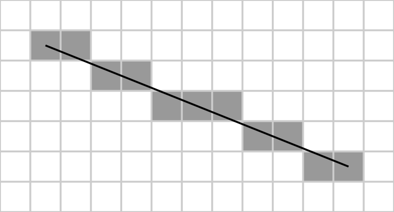
Straight line segments are one of the simplest depicted forms, so often this is one of the first concepts studied in geometry. They are described by two separate points (the initial and final) and the line connecting them. The most commonly used algorithm for rasterization of a straight segment is called the Bresenham algorithm .
Step by step, the Bresenham algorithm looks like this:
- Getting at the entrance of the starting and ending points of the line segment.
- Determining the direction of the segment by direct calculation of its properties dx and dy ( dx=x1−x0 , dy=y1−y0 ).
- The definition of properties
sx,syand error detection (the mathematical definition is given below). - Round each point in the segment to a pixel above / below.
Before implementing the Bresenham algorithm, let's create a base segment class that can be used in the engine:
LineSegment Class { Variables: int startX, startY; // int endX, endY; // Function: array returnPointsInSegment; // , } If you need to perform a transformation with a new class
LineSegment, then it is enough to apply the corresponding transformation to the starting and ending points LineSegment, and then pass them back to the class. All points between the institutes will be processed when drawing itself LineSegment, because the Bresenham algorithm requires only the start and end points to search for all subsequent points.To embed a class
LineSegmentin an existing engine, we need to add a function to the class draw(), so I refused to use the function returnPointsInSegment. This function will return an array of all points that are in the line segment, which will allow us to draw and cut the segment conveniently.The function
returnPointsInSegment()will look something like this (in javascript): function returnPointsInSegment() { // var pointArray = new Array(); // var x0 = this.startX; var y0 = this.startY; var x1 = this.endX; var y1 = this.endY; // , var dx = Math.abs(x1-x0); var dy = Math.abs(y1-y0); var sx = (x0 & x1) ? 1 : -1; // x var sy = (y0 & y1) ? 1 : -1; // y var err = dx-dy; // // pointArray.push(new Point(x0,y0)); // while(!((x0 == x1) && (y0 == y1))) { var e2 = err * 2; // // , ( ) if(e2 => -dy) { err -= dy; x0 += sx; } if(e2 < dx) { err += dx; y0 += sy; } // pointArray.push(new Point(x0, y0)); } return pointArray; } The easiest way to add the rendering of straight line segments to a camera class is to add a simple structure
if, for example, like this: // if (class type == Point) { // } else if (class type == LineSegment) { var segmentArray = LineSegment.returnPointsInSegment(); // , , } And this is all that is needed for the work of our first class form! If you want to learn more about the technical aspects of the Brezenham algorithm (especially errors), then you can read about them in an article in Wikipedia .
Circumference

Source: http://en.wikipedia.org/wiki/File:Bresenham_circle.svg
Rasterization of a circle is slightly more complicated than rasterization of a straight line segment. For most of the work, we will use the center-point algorithm of the circle , which is a development of the Brezenham algorithm. That is, it consists of similar stages, with some differences.
The new algorithm will work like this:
- Getting the center point and the radius of the circle.
- Forcing points in each main direction
- Cycling each quadrant, drawing their arcs
The circle class is very similar to the straight segment class and will look something like this:
Circle Class { Variables: int centerX, centerY; // int radius; // Function: array returnPointsInCircle; // , Circle } The function
returnPointsInCircle()will behave in the same way as a class function LineSegment, returning an array of points so that the camera can render and cut them off. This allows the engine to handle many different forms, each of which needs to make only minor changes.Here's what the function will look like
returnPointsInCircle()(in javascript): function returnPointsInCircle() { // var pointArray = new Array(); // , var f = 1 - radius; // ( ) var ddFx = 1; // x var ddFy = -2 * this.radius; // y var x = 0; var y = this.radius; // , // pointArray.push(new Point(this.centerX, this.centerY + this.radius)); pointArray.push(new Point(this.centerX, this.centerY - this.radius)); pointArray.push(new Point(this.centerX + this.radius, this.centerY)); pointArray.push(new Point(this.centerX - this.radius, this.centerY)); while(x < y) { if(f >= 0) { y--; ddFy += 2; f += ddFy; } x++; ddFx += 2; f += ddFx; // pointArray.push(new Point(x0 + x, y0 + y)); pointArray.push(new Point(x0 - x, y0 + y)); pointArray.push(new Point(x0 + x, y0 - y)); pointArray.push(new Point(x0 - x, y0 - y)); pointArray.push(new Point(x0 + y, y0 + x)); pointArray.push(new Point(x0 - y, y0 + x)); pointArray.push(new Point(x0 + y, y0 - x)); pointArray.push(new Point(x0 - y, y0 - x)); } return pointArray; } Now we just add another construction
ifto the main draw loop, and these circles will be fully integrated into the code!Here is what the updated rendering loop might look like:
// if(class type == point) { // } else if(class type == LineSegment) { var segmentArray = LineSegment.returnPointsInSegment(); //loop through points in the array, drawing and culling them as we have previously } else if(class type == Circle) { var circleArray = Circle.returnPointsInCircle(); // , , } Now that we have two new classes, let's do something!
Rasterization wizard
This time our program will be simple. When the user presses the mouse button, we will draw a circle with the center at the point of pressing and with a random radius.
Let's look at the code:
main{ // API // ( ) var camera = new Camera(); // camera.objectsInWorld[]; // 100 // camera.minX = 0; camera.maxX = screenWidth; camera.minY = 0; camera.maxY = screenHeight; camera.minZ = 0; camera.maxZ = 100; while(key != esc) { if(mouseClick) { // camera.objectsInWorld.push(new Circle(mouse.x,mouse.y,random(3,10)); // camera.drawScene(); } } } If everything works out successfully, then you can draw excellent circles with the help of the engine.
Conclusion
Having added basic rasterization capabilities to the engine, we finally start drawing useful objects on the screen! So far there has been nothing difficult, but if you want, you can try to draw people from segments and circles, or something like that.
In the next part, we take another look at rasterization. Only this time we will add two more classes to the engine: triangles and quadrilaterals.
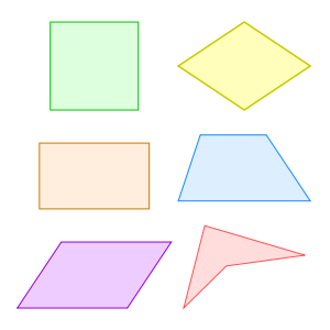
Part 5: rasterization of triangles and quadrilaterals
To create classes
Triangleand Quadwe will actively use the class LineSegment.Rasterization of triangles

The implementation of the class
Trianglein the engine is quite simple, especially due to the use of the class LineSegment, in which all rasterization will occur. This class allows you to assign three points and draw line segments between them to create a closed triangle.The draft of the class will look like this:
Triangle Class { Variables: // int Point1X, Point1Y; int Point2X, Point2Y; int Point3X, Point3Y; Function: array returnPointsInTriangle; // } For the sake of standardization, we assume that the three points are declared in a clockwise triangle.
Then using the class,
LineSegmentyou can write the following function returnPointsInTriangle(): function returnPointsInTriangle() { array PointsToReturn; // // PointsToReturn.push(new LineSegment(this.Point1X, this.Point1Y, this.Point2X, this.Point2Y)); PointsToReturn.push(new LineSegment(this.Point2X, this.Point2Y, this.Point3X, this.Point3Y)); PointsToReturn.push(new LineSegment(this.Point3X, this.Point3Y, this.Point1X, this.Point1Y)); return(PointsToReturn); } Not bad, right?We have already done a lot of work in the classroom
LineSegment, so we just have to sequentially connect the segments together to create more complex shapes. This allows us to easily create much more complex polygons (polygons) on the screen simply by adding new ones LineSegment(and storing more points in the class itself).Now let's see how to add more points to this system by creating a class of a square.
We work with squares
To implement the class of control quadrangles you just need to add a few additions to the class
Triangle. With another set of points, the class of the quadrilateral will look like this: Quad Class { Variables: int Point1X, Point1Y; // int Point2X, Point2Y; int Point3X, Point3Y; int Point4X, Point4Y; Function: array returnPointsInQuad; // } Now we just need to add another straight line segment to the function
returnPointsInQuad, like this: function returnPointsInQuad() { array PointsToReturn; // // PointsToReturn.push(new LineSegment(this.Point1X, this.Point1Y, this.Point2X, this.Point2Y)); PointsToReturn.push(new LineSegment(this.Point2X, this.Point2Y, this.Point3X, this.Point3Y)); PointsToReturn.push(new LineSegment(this.Point3X, this.Point3Y, this.Point4X, this.Point4Y)); PointsToReturn.push(new LineSegment(this.Point4X, this.Point4Y, this.Point1X, this.Point1Y)); return(PointsToReturn); } Although this way of creating classes is fairly simple, there is a much easier way to encapsulate all polygons into one class. With the help of the magic of loops and arrays, we can implement a class of polygons that can accommodate forms of almost any complexity!
We work with polygons
To create an ever expanding polygon class, we need two serious steps. The first is to put all the points in an array, which will give us a sketch of a class like this:
Polygon Class { Variables: array Points; // Function: array returnPointsInPolygon; //, } The second is the use of a loop to bypass the entire indefinite number of straight line segments in a function
returnPointsInPolygon(), which may look something like this: function returnPointsInPolygon { array PointsToReturn; // // ( ) for(int x = 0; x < this.Points.length; x+=2) { if( ) { // PointsToReturn.push(new LineSegment(this.Points[x], this.Points[x+1], this.Points[x+2], this.Points[x+3])); } else if( ) { // PointsToReturn.push(new LineSegment(this.Points[x-2], this.Points[x-1], this.Points[0], this.Points[1])); } } // return PointsToReturn; } Having added this class to the engine, we can create anything in one line of code - from a triangle to a 39-sided monster.
Polygon Creator
To experiment with a new polygon class, let's create a program that demonstrates all of its capabilities. Our program will allow the user to add or remove sides of the displayed polygon using the keys. Of course, you need to make a limit on the number of sides of the polygon, because with less than three sides, it ceases to be a polygon. We do not really care about the upper limit of the sides of the landfill, because it will scale well. However, we will limit the number of sides to ten, because we will set new points in the code.
Program specifications can be broken down into the following parts:
- The initial drawing of the polygon on the screen.
- Pressing the A key reduces the number of sides of the polygon by 1.
- When you press the S key, increase the number of sides of the polygon by 1.
- The number of sides of the landfill should not be less than 3.
- The number of sides of the landfill should not be more than 10.
Let's see how our code should look like:
main{ // API // ( ) var camera = new Camera(); // camera.objectsInWorld[]; // // camera.minX = 0; camera.maxX = screenWidth; camera.minY = 0; camera.maxY = screenHeight; camera.minZ = 0; camera.maxZ = 100; //c var threeSides = new Array(100,100,100,50,50,50); var fourSides = new Array(points in here); var fiveSides = new Array(points in here); var sixSides = new Array(points in here); var sevenSides = new Array(points in here); var eightSides = new Array(points in here); var nineSides = new Array(points in here); var tenSides = new Array(points in here); // var sidesArray = new Array(threeSides, fourSides, fiveSides, sixSides, sevenSides, eightSides, nineSides, tenSides); // var polygonPoints = 3; // var polygon = new Polygon(sidesArray[0][0], sidesArray[0][1], sidesArray[0][2], sidesArray[0][3], sidesArray[0][4], sidesArray[0][5],); // camera.drawScene(); // escape while(key != esc) { if(key pressed == 'a') { // 3 if(polygonPoints != 3) { // polygonPoints--; // , } // camera.drawScene(); } else if(key pressed == 's') { // 10 if(polygonPoints != 10) { // polygonPoints++; // , } // camera.drawScene(); } } } Our small program will now allow you to change the polygon on the screen! If you want to make the program a little more powerful, you can add some algorithm to the polygon part to simplify scaling. I don’t know if it exists, but if so, you can easily get an infinitely scalable polygon!
Conclusion
Now there are quite a lot of rasterization operations in our engine, which allows us to create almost any necessary shape (however, some of them will require a combination). In the next part, we move away from drawing forms and talk about other properties. If you are interested in adding some color to the screen, then read the next part!
Part 5: colors
Our theoretical engine already contains almost everything needed, namely:
- Classes
PointandVector(engine building blocks). - Functions of transformations of points.
- Class
Camera(sets the scope and cuts off points outside the screen). - Three classes for rasterization (line segments, circles and polygons).
Now let's add colors!
Color for all!
Our engine will process colors, keeping their values in class
Point. This will allow each point to have its own color, which will greatly simplify the calculations of lighting and shading (at least for a person - sometimes this engine code is less effective). When calculating the illumination and shading of the scene, we can create a function with a list of points and process all of them taking into account the distance to the light source in order to change their color accordingly.One of the most common ways to store color in programming is to use red, green, and blue values (usually called additive color mixing). By saving a value from 0 to 255 of each of the color components, you can create a large palette of colors. (Thus, most of the APIs determine the color, so it’s logical to use this method for compatibility).
Depending on the graphics API used, these values can be transmitted either in decimal (
255,0,0) or hexadecimal form ( 0xFF0000or #FF0000). We will use the decimal format, because it is much easier to work with it. In addition, if your graphics API uses hexadecimal values, then it most likely has a function for converting decimal values to hexadecimal values, that is, this will not be a problem.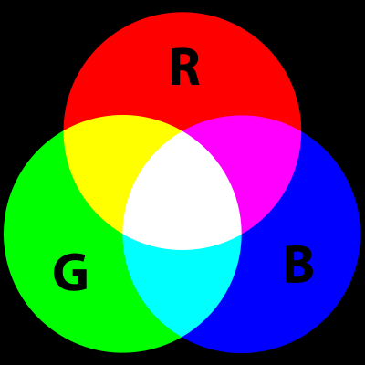
To start the implementation of a color model, we add three new variables in the Point class:
red, blueand green. So far, nothing incomprehensible happens, but here’s how the sketch of our class should now look Point: Point Class { Variables: num tuple[3]; //(x,y,z) num red, green, blue; // r, g, b Operators: Point AddVectorToPoint(Vector); Point SubtractVectorFromPoint(Vector); Vector SubtractPointFromPoint(Point); Null SetPointToPoint(Point); Functions: drawPoint; // } That's all we need to store the color of the point. Now we just need to change the camera's render function to use the specified color.
The appearance of the function depends very much on the graphic API used, but all interfaces usually have a similar function:
object.setColor(red, green, blue) If your graphics API uses hexadecimal, not decimal, color values, the function will look something like this:
object.setColor(toHex(red,green,blue)) This line uses the function
toHex()(again, in different API the names of the functions will be different), converting the RGB value into a hexadecimal value, so that you do not have to do it manually.By making these changes, you can get colored dots in the scene. In the next step, we will add rasterization classes so that we can color the forms entirely.
To add this capability to classes, we just need to add color management to the constructor functions. It might look like this:
lineSegment::constructor(startX, startY, endX, endY, red, green, blue) { this.startX = startX; this.startY = startY; this.endX = endX; this.endY = endY; this.red = red; this.green = green; this.blue = blue; } Now we just need to change the function of the returned points so that each point in the array has the specified color. The new feature will look like this:
function returnPointsInSegment() { // var pointArray = new Array(); // var x0 = this.startX; var y0 = this.startY; var x1 = this.endX; var y1 = this.endY; // , var dx = Math.abs(x1-x0); var dy = Math.abs(y1-y0); var sx = (x0 & x1) ? 1 : -1; // x var sy = (y0 & y1) ? 1 : -1; // y var err = dx-dy; // // pointArray.push(new Point(x0,y0,this.red,this.green,this.blue)); // while(!((x0 == x1) && (y0 == y1))) { var e2 = err * 2; // // , ( ) if(e2 => -dy) { err -= dy; x0 += sx; } if(e2 < dx) { err += dx; y0 += sy; } // pointArray.push(new Point(x0, y0,this.red,this.green,this.blue)); } return pointArray; } Now each point on the line segment has the same color, transmitted in the line segment. You can use this method to specify colors and other rasterization classes, and then your scene will be painted with different colors!
Let's use our new features by writing a program.
Experimenting with 16.7 million colors
With the help of additive color mixing, we can easily create more than 16.7 million colors using a simple entry (
r,g,b). We will create a program that uses all this huge amount of colors.We will allow the user to control the red, green and blue components of the color by pressing the keys and he can choose any color he likes.
The program will have the following specifications:
- Drawing an object on the screen.
- When you press the A key, the value of the red component decreases, and when you press Q , it increases.
- When you press the S key, the value of the green component decreases, and when you press W , it increases.
- When you press the D key, the value of the blue component decreases, and when you press E , it increases.
- Object redrawing after color update.
- It is necessary to limit the values of the components and not let them go beyond the limits from 0 to 255.
Given all this, let's look at how the outline of our program might look like:
main{ // API // ( ) var camera = new Camera(); // // camera.minX = 0; camera.maxX = screenWidth; camera.minY = 0; camera.maxY = screenHeight; camera.minZ = 0; camera.maxZ = 100; // , var red, green, blue; // while(key != esc) { if(key press = 'a') { if(red > 0) { red --; object.red = red; // } } if(key press = 'q') { if(red < 255) { red ++; object.red = red; // } } if(key press = 's') { if(green > 0) { green --; object.green = green; // } } if(key press = 'w') { if(green < 255) { green ++; object.green = green; // } } if(key press = 'd') { if(blue > 0) { blue --; object.blue = blue; // } } if(key press = 'e') { if(blue < 255) { blue ++; object.blue = blue; // } } } } Now we can experiment with the object and give it any color!
Conclusion
We added color to the engine and now we have everything we need to work with lighting. In the next section, we will look at the process of creating a light source and write functions that allow these sources to influence the colors of the dots.
Part 7: dynamic lighting
In this part we will look only at the very basics of dynamic lighting, so don't be too scared (this whole topic is very extensive and entire books are written about it).
More specifically, we will create a one-point one-color dynamic lighting system with a constant radius. But before we begin, let's look at some of the previously created classes that will be useful to us.
Reiteration
Our dynamic lighting will be processed for each point in the process of their display on the screen. This means that we will actively use our two previous classes: class
Pointand class Camera. Here's what they look like: Point Class { Variables: num tuple[3]; //(x,y,z) Operators: Point AddVectorToPoint(Vector); Point SubtractVectorFromPoint(Vector); Vector SubtractPointFromPoint(Point); Null SetPointToPoint(Point); Functions: drawPoint; // } Camera Class { Vars: int minX, maxX; int minY, maxY; int minZ, maxZ; array objectsInWorld; // Functions: null drawScene(); // } Let's create a simple lighting class based on this information.
Lighting class
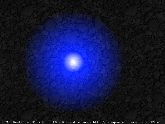
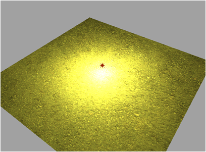
An example of dynamic lighting. Source: http://redeyeware.zxq.net
To work, the lighting class will need some information, namely, position, color, type and intensity (or radius of the light).
As I said earlier, the lighting will be calculated for each point before drawing it. The advantages of this approach are that it is simpler for the engine structure and transfers most of the program load to the central processor. If you calculate the lighting in advance, the load will move to the hard disk of the computer and depending on the design of the engine it will be easier or more difficult to implement.
Given all this, the class will look something like this:
Lighting Class { Variables: num position[3]; //(x,y,z) num red = 255; //, r num green = 255; //, g num blue = 255; //, b string lightType = "point"; // num radius = 50; // } For the sake of simplicity, we will keep all these values rigidly set for now, but if you want to expand the capabilities of the lighting classes, you can easily change these values through other functions, the constructor, etc.
However, all the important calculations for dynamic lighting will be performed in the camera class, so let's look at it.
Shine? Camera? Motor.
Another example of dynamic lighting. Source: http://blog.illuminatelabs.com/2010/04/hdr-and-baked-lighting.html
Now we will add a new variable to the camera class that we use to store the light source. For now, this variable will contain only one instance of the source, but it can be easily extended so that several point sources can be stored.
Immediately before drawing the point, we will check whether it is in the radius of the light source. If it is, then we need to find the distance between the point and the position of the source, and then change the color of the point in accordance with the distance.
Given all this, we can add a code similar to the code from the camera function
drawScene(): if(currentPoint.x >= (light.x - light.radius)){ // if(currentPoint.x <= (light.x + light.radius)){ // if(currentPoint.y >= (light.y - light.radius)){ // if(currentPoint.y <= (light.y + light.radius)){ // // (distance) // (percentage = distance / radius) point.red += (light.red * percentage); // , point.green += (light.green * percentage); // , point.blue += (light.blue * percentage); // , } } } } As you can see, our way of changing the color of a point is not too complicated yet (however, there are many others that can be used if desired). We change the color of the point to a percentage, depending on the distance to the center of the light source. Our lighting method completely ignores shadowing, so the points far from the light source do not become darker, and the objects do not block the light from other objects that may be behind them.
Follow the light
This time in the program we will use several permanent forms on the screen. You can choose any form, but in our example I use a few simple points. When the user clicks on the screen, we create a light source at this point. The next time we press, we move the point to a new position, and so on. This will allow us to observe the dynamic lighting in action.
Here is what the program might look like:
main{ // API // ( ) var camera = new Camera(); // // camera.minX = 0; camera.maxX = screenWidth; camera.minY = 0; camera.maxY = screenHeight; camera.minZ = 0; camera.maxZ = 100; // while(key != esc) { if(mouseClick) { if(firstClick) { // } else { // } camera.drawScene(); } } Now you can appreciate the dynamic lighting in action and see how much depth it adds to the game engine.
Conclusion
Although our dynamic lighting is simple, you can easily expand it if you like. Some fairly simple but interesting additions:
- variable radius of illumination
- changeable color of lighting (instead of a monotonous change of color, you can change it to a part of the specified color)
- (, ..)
Source: https://habr.com/ru/post/334580/
All Articles