Experience of using FPGA boards DE10-Standard and DMA PL330
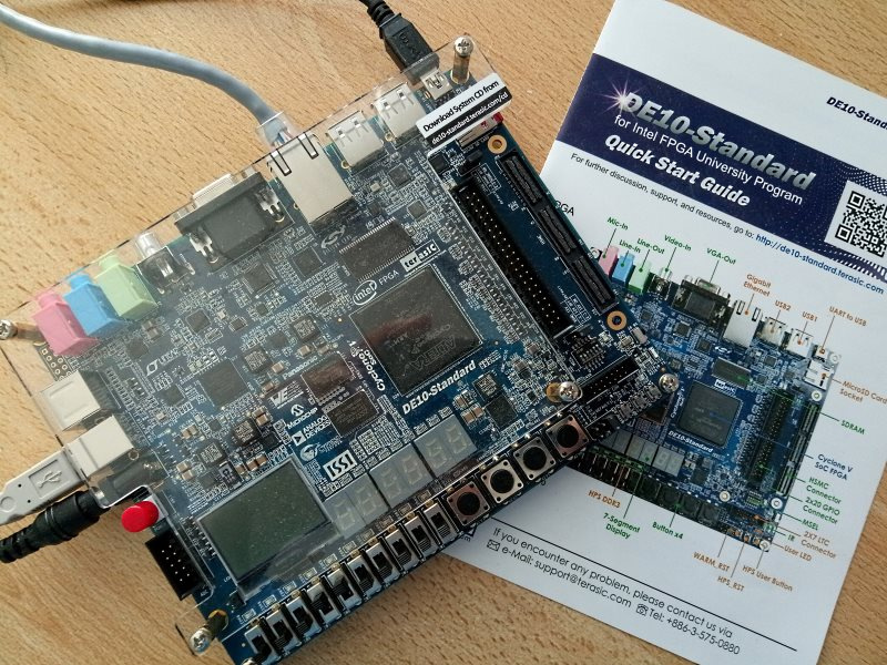
Got a Terasic DE10-Standard fee. It has a lot of interesting things: a built-in JTAG programmer, LEDs, switches, buttons, Audio / VGA / USB / Ethernet connectors. I think that there is no special need to list all its capabilities, because anyone can read the specification of the board on the manufacturer’s website .
For me, it is important that the board is an FPGA chip Cyclone V SX - 5CSXFC6D6F31C6N. This microcircuit contains two ARM Cortex-A9 and 110K FPGA gates. This is the real SoC HPS: System-On-Chip, Hard Processor System. With such resources, you can try to do quite complex projects. Further I will tell about my experience of using the board.
')
It is very easy to download a Linux image from the site of a web site and prepare a bootable SD card for the DE10-Standard board. Linux OS boots from SD, the board comes to life and demonstrates its capabilities.
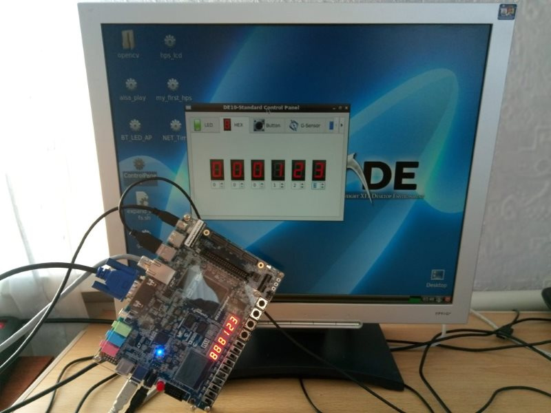
Once Linux has booted, you can find the test application icon on your desktop. This test GUI application allows you to turn on and off individual LEDs on the board, view the status of switches and buttons, set values on 7-segment indicators, and so on. There are a lot of interesting things. When I played with this program, you think that now you can quickly make your own project and launch it quickly.
I do not consider myself a new FPGA developer. I did projects with software processors and imagine what a Linux kernel is. I myself participate in the development of developer boards with Altera / Intel FPGAs . However, to be honest, this is my first experience with SoC HPS-FPGA. When I started to make my own project for this board, precisely for this FPGA, I realized that in fact it would not be easy.

Of course, the DE10-Standard board itself is not to blame. There is some illusion of ease of development: here is an image of an SD card from terraces, there are source codes for a sample project for FPGAs and sishny sources for test programs. It would seem, take adapt to your needs and everything will work. But no.
It is necessary to understand that the first impression of ease of development is deceptive. What can be seen at first sight is just the tip of the iceberg.
I had to read and study a lot, for example:
1. A DE10-Standard_v.1.2.0_SystemCD disk is attached to the board and it contains 38 PDF files of various documentation, diagrams and manuals.
2. A simple technical description from Intel's “ Cyclone V Hard Processor System Technical Reference Manual ” contains 3536 pages.
Of course, I don’t have to read them all at once, I thought I wouldn’t read them at all, I’ll manage with my knowledge and experience, but I still had to read and understand.
There is still a good resource that contains even more documentation, source codes of examples and even a forum. It makes life on the one hand easier, and on the other - even more difficult, because you have to read and absorb even more information ... Unfortunately, even on the rocketboard forum, it is not always possible to find answers to your questions.
Thus, the development of the project is quite complex, because the subject of the development of SoC HPS is difficult.
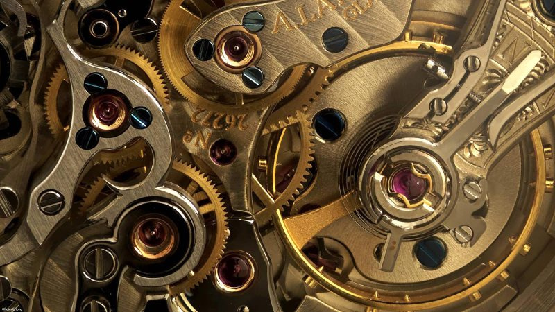
Imagine a clock mechanism with lots of gears. Each gear must exactly match the next one - otherwise nothing will spin. The same is the case with the HPS-FPGA system. The system consists of a lot of software and hardware components: Preloader, U-BOOT, Linux kernel and driver, a DTB file is generated from the DTS file, then RootFS must be created and, of course, the hardware system in the FPGA is developed: the FPGA SoC project will contain several IP blocks, hardware registers mapped into memory, clock frequencies and domains, I / O signals and so on and so forth ...
I suppose that I know how to create a project for an FPGA for my SoC, and I think that it should work well for about 80% since I do not see obvious errors in the project. I also think about how to write a DTS file that describes my hardware platform. Suppose I am sure that I wrote the DTS file correctly at 80%. A DTB file is generated from the DTS file. Then, to my FPGA hardware, I have to write a kernel driver. It's not easy, but I can write drivers. I hope I did not make a lot of mistakes there? I hope my driver is correct, well, at least 80%. But what about the Preloader? Preloader is the first program to be read and launched from the SD card and it must program the necessary hardware configuration registers of the system on a chip. Have I made the Preloader correctly? Well, let's say, I'm 80% sure. Now, if you think about it, what is the probability that my system will work? I think that somewhere like this: 0.8 * 0.8 * 0.8 * 0.8 = 0.4096 ... The more components in the system, the worse. If something does not work or nothing at all (for example, kernel panic), then it is rather difficult to understand where the problem is - it can be everywhere.
The purpose of my work was to make an HPS-FPGA project that uses DMA transactions to transfer data from system memory to FPGA and back from FPGA to system memory. Using DMA should unload the processor. On Habré there was already an article about the implementation of DMA in FPGA Cyclone V , however, I did not want to go by creating my own controller, as Des333 did ... I wanted to use the PL330 controller already in the system.
Working with the DE10-Standard Board for a while, I gained invaluable experience. If I may, I want to give some advice to those who decide to start developing SoC HPS in FPGA.
Prepare a fee for development
This is probably an obvious tip. There is an SD card image that contains the necessary files to start the system: an FPGA image, a DTB file, a U-BOOT, and a Linux kernel zImage. Additional sections contain Preloader and RootFS. If I develop a SoC HPS project for the FPGA, I compile it in the Quartus Prime CAD environment and the result (RBF, Raw Binary File) should be written to the SD card. Then I compile the Linux kernel and my driver as part of the kernel. I also need to write the resulting files to the SD Card.
There is no point in pulling the SD card out of the board, and inserting it into the card reader of a computer or laptop to write files to the card. This may take too much time. In addition, frequent plug / unplug may break the SD card slot in the card or laptop. I recommend configuring U-BOOT so that the necessary files are downloaded from the network from the TFTP server.
The board has a UART-to-USB connector for connecting it via a USB cable to the developer's computer. I open the terminal program, for example, PUTTY, and turn on the board. We immediately see how the messages from the U-BOOT ran in the terminal. Download can be interrupted if you immediately press any key in the terminal.
I added some variables to the U-BOOT environment:
ethaddr=fe:cd:12:34:56:67 ipaddr=10.8.0.97 serverip=10.8.0.36 xfpga=tftpboot 100 socfpga.rbf; fpga load 0 100 $filesize; run bridge_enable_handoff; tftpboot 100 socfpga.dtb xload=run xfpga; tftpboot 8000 zImage; bootz 8000 – 100 On the computer of the IP developer 10.8.0.36 I installed the TFTP server. In the / tftpboot folder, I store socfpga.rbf (Raw Binary File) - the result of compiling the SoC FPGA project in Quartus Prime. In addition, I also store socfpga.dtb in the same folder - the corresponding Device Tree Blob and Linux kernel zImage file.
Now, when I turn on the power on the board, I immediately interrupt the normal download by pressing any key in the terminal and enter the command:
>run xloadWith this command, U-BOOT downloads the necessary files from the TFTP server, initializes the FPGA with the latest compiled image of the project and loads my last zImage. Quick and easy. When I make a change in the FPGA project, I compile the project with a quarter, copy the result to the / tftpboot folder. In the same way, I compile the Linux kernel, I copy the result of the compilation to the / ftfpboot folder. Reboot the board, do a “run xload” and now you can try to debug the new system.
2. Try to find the opensource example of the SoC-HPS project as similar as possible to what you are going to do.
Captain obvious. Of course, a competent engineer can do everything from scratch. However, you can save some time by finding the source of a project similar to the one you are going to do.
The original DE10-Standard_v.1.2.0_SystemCD contains two sample projects for HPS-FPGA. The first project is the DE10_Standard_GHRD, which is a minimal feature, the Linux console, a simple memory-mapped peripheral, such as I / O ports for LEDs, buttons and switches. The second example, DE10_Standard_FB, is more complicated. Here, a framebuffer, a video controller, a device for capturing and decoding a video signal, and a number of other possibilities are already implemented in the FPGA. This allows you to run a full-fledged desktop Linux. If you are satisfied with these examples - then everything is fine, take and use.
Personally, I wanted to find an example using the DMA controller, since I wanted to unload the CPU during data transfer from system memory to FPGA and back from FPGA to system memory. I looked for such an example and found it on the rocketboards site .
An example is actually not very, but at least something, you can try to do something. Cyclone V HPS has a PL330 built-in DMA controller and I would like to try using it. I took the IP crust from the Loopback_FIFO example project and inserted it using the Quartus Prime QSYS into my clone of the DE10_Standard_GHRD project. Unfortunately, I spent a lot of time writing the correct DTS file to my project, the DTS file was not in the sample archive. Also, I did not immediately realize that the Linux kernel already has an example of a DMA driver in arch / arm / mach-socfpga / fpga-dma.c . I realized it was too late when I almost wrote my own driver.
Despite these difficulties, I still advise you to start your development by searching for existing examples, projects and solutions. Find a few examples, choose the best one for you - start with it.
3. Use the Linux kernel source as documentation
With Cyclone V HPS FPGA, I am developing a new hardware platform. Most likely I will have to write my own driver for the new hardware in the FPGA. There are a lot of articles on the Internet on how to write Linux kernel level drivers. But keep in mind that many of these articles are outdated a long time ago, contain incorrect examples, and call the old kernel API.
If you select a specific version of the Linux kernel for a project, then all the information about how to write drivers can be gathered specifically from the sources of this version of the kernel and this will be the most up-to-date information. Examples of drivers in the ./drivers folder, current documentation in the ./Documentation folder, examples of writing * .DTS files in the ./arch/arm/boot/dts folder
In my case, for my project with a DMA controller, the documentation about writing DMA drivers was obtained from ./Documentation/dmaengine/* files.
The kernel sources can help in writing the DTS file - for me the DTS file was a very big problem. The DTS file in text form describes the hardware resources of the system. Then DTS is compiled into a DTB file, which is then used by the kernel in such a way that drivers can know which resources belong to the devices.
As I understand it, theoretically, the development should go like this:
- We develop the hardware system in the Quartus Prime QSYS CAD system, configure the HPS parameters, add components and IP cores to the system, connect the components. Generate the system using QSYS and get the result soc_system.qsys and soc_system.sopsinfo files.
- Create a DTS file from a * .sopsinfo file using the command line:
>sopc2dts --input soc_system.sopcinfo --output socfpga.dts --board soc_system_board_info.xml --board hps_clock_info.xml - Create a DTB from a DTS file:
>dtc -I dts -O dtb -o socfpga.dtb socfpga.dts
I read this manual on the rocketboards pages , but this method somehow does not work very well (does not work at all). For myself, I realized that the only working method is to manually correct an existing example of a DTS file by adapting it to your hardware project.
As I already wrote, kernel sources can help in writing a DTS file. I really did not immediately understand this, but when I did, it went faster. You need to use the kernel source as documentation!
Let's see an example of a DMA driver from ./driver/dma/fpga-dma.c
The driver calls the API function platform_driver_probe () and passes a pointer to the structure as an argument:
#ifdef CONFIG_OF static const struct of_device_id fpga_dma_of_match[] = { {.compatible = "altr,fpga-dma",}, {}, }; MODULE_DEVICE_TABLE(of, fpga_dma_of_match); #endif static struct platform_driver fpga_dma_driver = { .probe = fpga_dma_probe, .remove = fpga_dma_remove, .driver = { .name = "fpga_dma", .owner = THIS_MODULE, .of_match_table = of_match_ptr(fpga_dma_of_match), }, }; static int __init fpga_dma_init(void) { return platform_driver_probe(&fpga_dma_driver, fpga_dma_probe); } This means that in the DTS file there must be a corresponding section with a compatible device name:
fpga_dma: fpga_dma@0x10033000 {
compatible = " altr,fpga-dma ";
That is, apparently the function platform_driver_probe will scan the DTB file to search for a device named fpga-dma from the manufacturer altr.
If the driver calls functions
csr_reg = platform_get_resource_byname(pdev, IORESOURCE_MEM, "csr"); data_reg = platform_get_resource_byname(pdev, IORESOURCE_MEM, "data"); This means that the DTS file must contain named registers with the same exact names “csr” and “data”. Otherwise, the driver will not be able to start.
In the same way, the kernel driver can query DMA channels by the name:
static int fpga_dma_dma_init(struct fpga_dma_pdata *pdata) { struct platform_device *pdev = pdata->pdev; pdata->txchan = dma_request_slave_channel(&pdev->dev, "tx"); if (pdata->txchan) dev_dbg(&pdev->dev, "TX channel %s %d selected\n", dma_chan_name(pdata->txchan), pdata->txchan->chan_id); else dev_err(&pdev->dev, "could not get TX dma channel\n"); pdata->rxchan = dma_request_slave_channel(&pdev->dev, "rx"); if (pdata->rxchan) And here is the corresponding fragment of the DTS file, which reflects the correlation of the kernel driver source and the DTS file:
fpga_dma: fpga_dma@0x10033000 { compatible = "altr,fpga-dma"; reg = <0x00000001 0x00033000 0x00000020>, <0x00000000 0x00034000 0x00000010>; reg-names = "<b>csr</b>", "<b>data</b>"; dmas = <&hps_0_dma 0 &hps_0_dma 1>; dma-names = "<b>rx</b>", "<b>tx</b>"; Thus, the DTS file must be written taking into account how the driver requests resources from it. If the named registers and the DMA channels are used, the names must match in the kernel source and in the DTS file. Only in this way are the two gears of the system: the kernel driver and the DTS / DTB can work together.
4. Remember that your source may not be the freshest.
I needed a compiler and source code for the Linux kernel so that I could start developing my driver and compiling the kernel for my FPGA system. That is why I downloaded the last (at that time) Intel SoC FPGA Embedded Development Suite v17.0 and installed it.
After the full installation, I saw a new folder ~ / intelFPGA / 17.0 / embedded / embeddedsw / sources , where the git_clone.sh script was located. I ran this script and got the kernel source right here ~ / intelFPGA / 17.0 / embedded / embeddedsw / sources / linux-sources .
Git branch turned out like this: sockfpga-4.1.22-ltsi-16.1-release . Kernel version 4.1.22 - so be it.
I accepted version 4.1.22 as a given and started working with this thread on these sources. I built a kernel and found that there is a DMA driver, called fpga-dma, and this driver works in general with my LoopbackFIFO IP core in my FPGA project. However, I noticed that the performance of transferring data from the memory of the system to the FPGA and back is very small - the transfer is carried out by single transfers, one word for several cycles. I rechecked my FPGA project a hundred times, and I rechecked the fpga-dma.c driver a hundred times, but I still could not understand why there is no burst transfers on the bus. I already started to deal with the source code of the PL330 DMA driver itself. Also, I had to read the Cyclone V Hard Processor System Technical Reference Manual about the HPS PL330 DMA controller. This DMA controller is very complex, it itself has its own set of instructions, you need to write your own program to it. An assembly language program for a PL330 DMA controller might look like this:
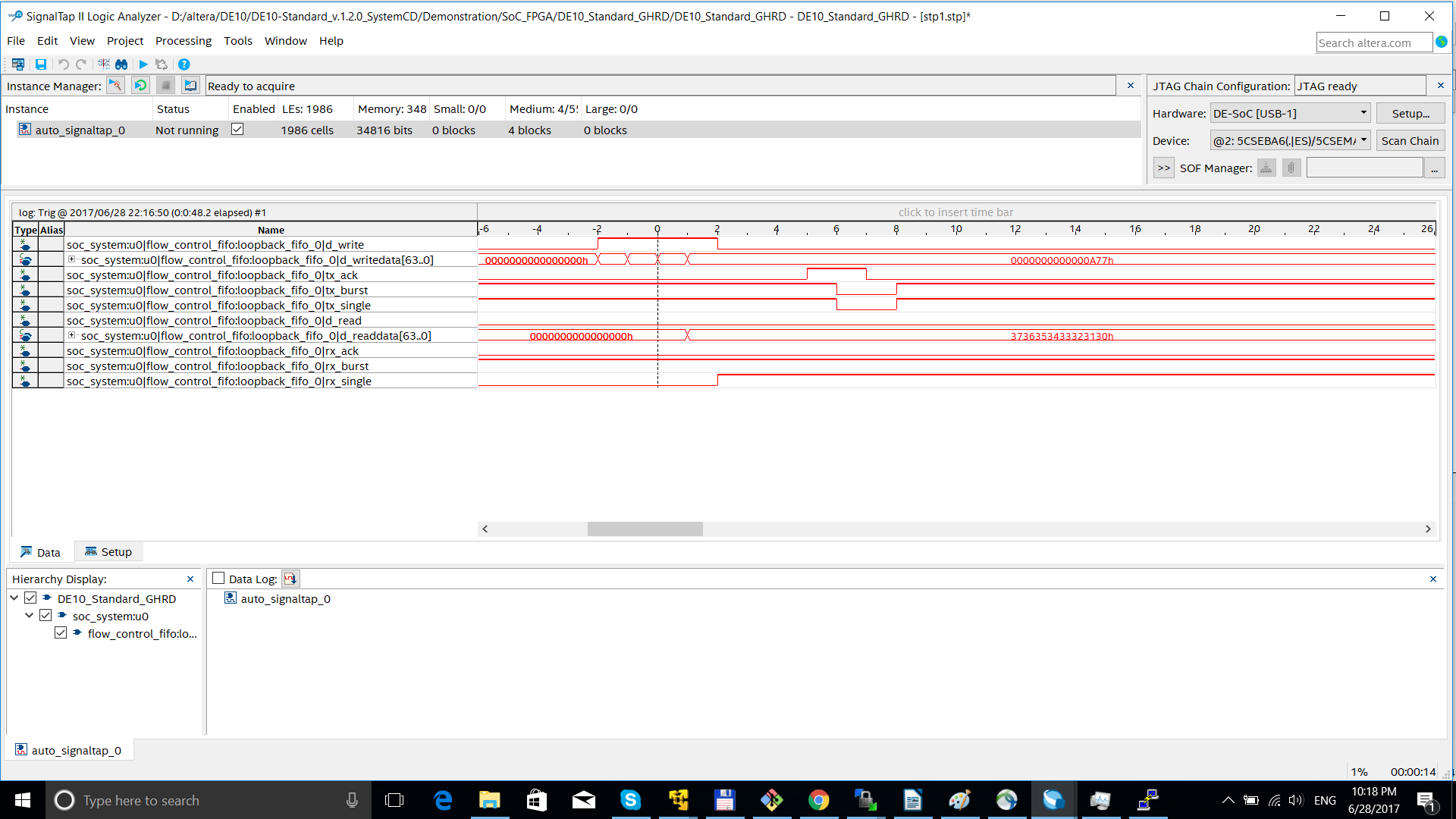
DMAMOV CCR, SB4 SS64 DB4 DS64 DMAMOV SAR, 0x1000 DMAMOV DAR, 0x4000 DMALP 16 DMALD DMAST DMALPEND DMAEND As a result of all my research, I realized that the driver ./drivers/dma/pl330.c never initializes the CCR register of the DMA controller for a burst transfer. I did not understand what to do, but later I discovered that newer versions of the kernel already contain a fix for this misunderstanding.
I manually added a patch to the source code of the DMA driver and received burst transfers! Here is a screenshot from the SignalTap screen where I capture the DMA Mem-to-Device transfer:
Thus, if one day you encounter a technical problem that you don’t know how to solve, recheck: what if your problem already has a fix in the more recent source code for the Linux kernel? As I understood, the problem with the block transfer of the DMA controller of PL330 is solved in kernel 4.6.
5. Carefully treat the individual parts of the system.
Of course, the development of an FPGA SoC system requires specific knowledge. Now I do not want to touch on the features and methods of developing IP cores or the syntax Verilog / VHDL. Of course, the developer should know a lot. However, I want to note that forcing all parts of the system to work together is not a very simple task. Too many gears that need to rotate synchronously.
I will try to give an example and my practice.
I tried to get the PL330 DMA controller driver to work with my IP core. I encountered such a problem: write operations to the device are successful, but read operations always end with a timeout. I tried to find a solution on the Internet and saw that many developers also ask about this problem, but there is no solution. In the system log, I see a message from the fpga-dma driver “Timeout waiting for RX DMA!”. But what's the problem? - unclear. Why is everything OK with TX transmission, but not with RX transmission? I swapped the RX and TX channels in the FPGA project, and got the opposite “Timeout waiting for TX DMA!”. What is wrong with my second DMA channel?
I use Quartus Prime Qsys to edit my SoC. One of the most important components of the SoC system is hps_0, the “Arria V / Cyclone V Hard Processor System”. I edited the properties of this component and made sure that I have both DMA channels turned on, and RX and TX:
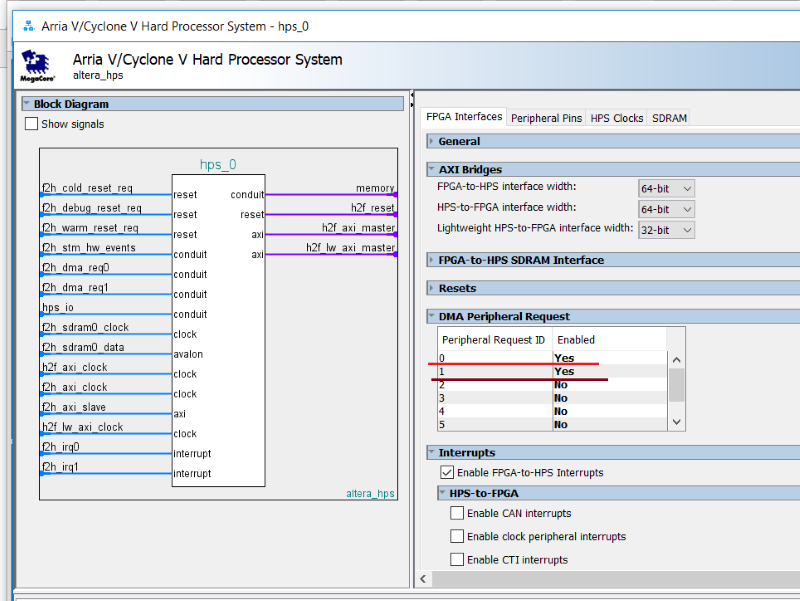
is that enough? In fact, of course not! Qsys generates soc_system components for Quartus Prime, but it also creates software components in the ./hps_isw_handoff/soc_system_hps_0 folder.
There is a file hps.xml in which you can see the following:
<hps> <system> <config name='DEVICE_FAMILY' value='Cyclone V' /> <config name='DMA_Enable' value='Yes Yes No No No No No No' /> <config name='dbctrl_stayosc1' value='true' /> <config name='main_pll_m' value='73' /> <config name='main_pll_n' value='0' /> <config name='main_pll_c0_internal' value='1' /> This means that later I have to generate the Preloader component, and this XML file is used to compile it. The compiled Preloader must be recorded in a special section of the SD card. When the system starts, the Preloader starts. That it includes all the necessary components of the system making the necessary entries in the special hardware registers.
Cyclone V HPS Reset Manager registers are located at the physical address 0xFFD05000 (Cyclone V Hard Processor System Technical Reference Manual). Some bits in the Reset Manager registers must be cleared to enable DMA on individual channels.
Oh well. I am changing the properties of the hps_0 component in Qsys and now I know that probably I should recompile Preloader and write it to SD.
But this is not the whole story!
If I use two DMA channels, then I need two interrupts for these two channels and they still need to be manually declared in the DTS file.
hps_0_dma: dma@0xffe01000 {
compatible = "arm,pl330-16.1", "arm,pl330", "arm,primecell";
reg = <0xffe01000 0x00001000>;
interrupt-parent = <&hps_0_arm_gic_0>;
interrupts = <0 104 4>, <0 105 4>;
clocks = <&l4_main_clk>;
Where are such strange numbers 104 and 105?
I had to read the Cyclone V HPS Reference Manual. I see that Generic Interrupt Controller has reserved lines of DMA IRQ 136 and 137:

However, for some reason the numbering begins “32”. So I decide that 136-32 = 104 and 137-32 = 105 are the correct numbers. These magic calculations give the correct values for the DTS file in the interrupts section. Without declaring the second IRQs for PL330 in the DTS file, the second DMA channel always got a timeout error in the kernel driver ... It turns out that I change the HPS properties in Qsys and because of this I may need to simultaneously change both the Preloader and the DTS file - and that’s all time to remember.
Conclusion
I had an initial project with an example of a DMA project, which I found on the pages of the rocketboard site. However, I adapted it and made it work on the DE10-Standard board and with the Linux 4.1 kernel.
This is probably not a great achievement, however:
- I wrote a DTS file that was not in the original project. It was quite difficult.
- I understood that it was necessary to make a kernel patch in order to get a block transfer (burst transfer).
- I connected the SignalTap analyzer to the FPGA project and now I can see the signals on the bus at the time of the DMA transfer
- Learned to write DMA kernel driver
- I hope that I understood the whole road-map of the developer for Cyclone V HPS
If someone wants to experiment with DMA in SoC, I recommend starting experiments with the Alter fpga-dma driver. It uses DebugFS, which allows using simple “cat”, “echo” commands directly in the terminal console to perform transactions in the DMA channel:

I hope this article will be useful to those who are just starting to work with the FPSGA SoC HPS Cyclone V.
View the source of the project here .
Source: https://habr.com/ru/post/334154/
All Articles