learnopengl. Lesson 2.2 - Lighting Basics
 The spread of light in the real world is an extremely complex phenomenon, depending on too many factors, and with limited computing resources, we cannot afford to take into account all the nuances in the calculations. Therefore, the lighting in OpenGL is based on the use of simplified mathematical models close to reality, which look quite similar, but are much easier to calculate. These lighting models describe the physics of light based on our understanding of its nature. One of these models is called the Phong lighting model . The Phong model consists of three main components: background (ambient), diffuse / diffuse (diffuse) and glare (specular). Below you can see what they are:
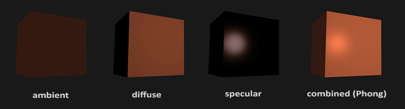
- Background lighting : even in the darkest scene there is usually always some kind of light (moon, high beam), so objects are almost never completely black. To simulate this, we use the ambient light constant, which will always give the object some hue.
- Diffuse lighting : imitates the effect of a directional light source on an object. This is the most visually significant component of the lighting model. The larger part of the object's surface facing the light source, the brighter it will be illuminated.
- Illumination of mirror highlights : imitates a bright spot of light (glare) that appears on shiny objects. The color of the specular highlights is often closer to the color of the light source than to the color of the object.
To create visually interesting scenes, we need to simulate at least these 3 components of the light component. Let's start with the simplest: with background lighting.
Background lighting
Light usually comes not from one, but from many sources of light being around us, even if we do not see them directly. One of the properties of light is that it can be diffused and reflected in many directions, reaching places that are not in direct view; Thus, light can be reflected from different surfaces and have an indirect effect on the lighting of the object. Algorithms that take into account these properties of light are called global illumination algorithms, but they are labor-intensive and / or complex.
Since we are not very fond of difficult and resource-intensive algorithms, we will begin with the use of a very simplified model of global illumination, namely, with Background illumination . In the previous section, you saw how a dim constant color was used, which was added to the color of a fragment of an object, and this created the impression that there was ambient light in the scene, although there was no direct source of such light.
Add background lighting to the scene is very simple. To do this, take the color of the light source, multiply it by a small constant background illumination factor, then multiply the resulting value by the color of the object and use the calculated value as the fragment color:
void main() { float ambientStrength = 0.1f; vec3 ambient = ambientStrength * lightColor; vec3 result = ambient * objectColor; color = vec4(result, 1.0f); } If you start the program now, you will see that the first component of the Phong lighting model has been successfully applied to your object. The object is rather dark, but not completely, because background lighting is applied to it (note that the cube of the lamp has not changed, because we use another shader to render it). The scene should look something like this:

Diffuse lighting
Background lighting itself does not produce any interesting results, but diffuse lighting has a very significant visual impact on the appearance of the object. The more perpendicular to the direction of the rays of the light source are the fragments of the object, the greater the brightness of the diffuse component of the illumination. To better understand diffuse lighting, take a look at the following image:

p> On the left, we see a beam emanating from a light source, aimed at some fragment of our object. We need to measure the angle of incidence of the beam on the fragment. The impact of the light source on the color of the fragment becomes maximum when perpendicular to the direction of the beam to the surface of the object. To measure the angle between the light beam and the fragment, we use the so-called normal vector , which is perpendicular to the fragment surface (the normal vector is depicted as a yellow arrow); we will talk about it later. Then the angle between the two vectors can be easily calculated using the dot product.
You may remember from the lesson on transformations that the smaller the angle between two unit vectors, the greater the result of the scalar product tends to 1.0. When the angle between both vectors is 90 degrees, the scalar product of these vectors becomes equal to 0. The same applies to the angle Θ: the more becomes, the less influence the light source has on the color of the fragment.
Note that to obtain (only) the cosine of the angle between both vectors, we will work with unit vectors (vectors of unit length), so we must make sure that all vectors are normalized, otherwise the scalar product of vectors will return a result greater than the cosine value (see Transformation lesson).
Thus, the value returned from the dot product can be used to calculate the power of the light source on the color of the fragment; This will lead to a different illumination of the fragments, depending on their orientation with respect to the direction of light rays.
So, what do we need to calculate diffuse illumination?
- Normal vector: vector perpendicular to the illuminated surface
- Directional light: direction vector, which is the difference between the position of the light source and the position of the fragment. To calculate this ray, we need the coordinate of the light source and the coordinate of the fragment.
Normal vectors
The normal vector is a (unit) vector perpendicular to the surface constructed on a given vertex. Since the vertex itself does not have a surface (this is just a point in space), adjacent vertices are used to find the normal vector. To calculate the normals of the vertices of a cube, we can do a little trick and apply a vector product to the faces, but since the cube is a fairly simple shape, we add the normals to the vertex data manually. An updated array of vertex data can be found here . Try to imagine the normals in the form of vectors directed perpendicular to the surfaces of the planes of the cube (the cube consists of 6 planes).
Since we added additional data to the array of vertices, we need to update the vertex lighting shader:
#version 330 core layout (location = 0) in vec3 position; layout (location = 1) in vec3 normal; ... Now, after adding each vertex of the normal vector and updating the vertex shader, we also need to update the vertex attribute pointers. Notice that the lamp object retrieves vertex data from the same array, but the vertex lamp shader does not use newly added normal vectors. We do not need to update either the lamp shaders or its attributes, but due to the change in the size of the array of vertices, we need to change the setting of the attribute pointers.
glVertexAttribPointer(0, 3, GL_FLOAT, GL_FALSE, 6 * sizeof(GLfloat), (GLvoid*)0); glEnableVertexAttribArray(0); For each vertex, we want to use only the first 3 float values, and skip the last 3 values, so we only need to update the stride parameter to a value equal to 6 sizes of the variable type GLfloat, that's all.
Working with an array of vertices, in which the shader does not use all the data, may not seem inefficient, but this data has already been loaded into the GPU memory from the array of the container object, so we do not need to load any new data. In practice, this approach is more efficient than creating a new VBO for the lamp.
All lighting calculations are performed in a fragment shader, so we need to redirect normal vectors from the vertex shader to the fragment shader. Let's do it:
out vec3 Normal; void main() { gl_Position = projection * view * model * vec4(position, 1.0f); Normal = normal; } It remains only to declare the corresponding input variable in the fragment shader:
in vec3 Normal; Diffuse color calculation
Now we have a normal vector for each vertex, but we still need vectors with coordinates of the light source and the fragment. Since the position of the light source is set to one variable that does not change, we will simply declare it in the fragment shader as a uniform variable:
uniform vec3 lightPos; And then assign it a value in the game loop (or outside it, since the value of this variable does not change). We use the lightPos vector announced in the previous lesson as the location of the light source:
GLint lightPosLoc = glGetUniformLocation(lightingShader.Program, "lightPos"); glUniform3f(lightPosLoc, lightPos.x, lightPos.y, lightPos.z); The last thing you need is the position of the current fragment. We are going to make all calculations of illumination in world space of coordinates, therefore, we will need the vertex positions needed in world coordinates. The transformation of a vertex position into world coordinates is achieved by multiplying its position attribute only by the model matrix (without view and projection matrices). This can easily be done in the vertex shader, so let's declare the output variable in it and calculate the coordinates of the vertex in the world space:
out vec3 FragPos; out vec3 Normal; void main() { gl_Position = projection * view * model * vec4(position, 1.0f); FragPos = vec3(model * vec4(position, 1.0f)); Normal = normal; } Finally, add the appropriate input variable to the fragment shader:
in vec3 FragPos; Now that all the necessary variables have been set, we can start the lighting calculations in the fragment shader.
The first thing we need to calculate is the direction vector between the light source and the fragment. We have already said that this vector is the difference in the positions of the light source and the fragment. As you may remember from the transformation lesson, we can easily calculate this difference by subtracting one vector from another. We also want to make sure that all the vectors of interest to us are of unit length, so we normalize both the vector of the direction of the source of light and the vector of normals obtained by subtracting:
vec3 norm = normalize(Normal); vec3 lightDir = normalize(lightPos - FragPos); When calculating the lighting, we usually don’t care about the size of the vectors or their location; we are only interested in directions. Since only the orientation of the vectors is a significant characteristic, almost all calculations are performed with vectors of unit length, since this simplifies most calculations (for example, the dot product). Therefore, when performing lighting calculations, always check whether you have normalized the corresponding vectors to ensure that they are really single. The absence of vector normalization is a very common error.
Next, using the scalar product of the vectors norm and lightDir , we need to calculate the magnitude of the effect of diffuse illumination on the current fragment. Then, this value is multiplied by the color of the light source, and as a result we get the diffuse illumination component, which will become darker as the angle between the vectors increases:
float diff = max(dot(norm, lightDir), 0.0); vec3 diffuse = diff * lightColor; If the angle between the vectors is more than 90 degrees, then the result of the scalar product will be negative, and we will get a negative component of diffuse light. For this reason, we use the max function, which returns the largest of the parameters passed to it, and ensures that the diffuse component of light (and, therefore, colors) will never be less than 0.0. Lighting models for negative color values do not exist, so if you are not one of eccentric artists, it’s better to stay away from negative colors.
Now that we have the background and diffuse components, we summarize their colors, and then multiply the result by the color of the object, thus obtaining the resulting color of the output fragment:
vec3 result = (ambient + diffuse) * objectColor; color = vec4(result, 1.0f); If your application (and shaders) are compiled successfully, you will see something like this:

Together with the diffuse lighting component, the cube begins to look more realistic. Try to imagine the normals of the planes of the cube, and then, moving around it to observe the brightness change, and see that as the angle between the normal and the direction of the light source increases, the fragments become darker.
If you have any difficulties, feel free to compare your source code with the full source code and fragment shader code .
Something else
Currently, we transfer the vectors of the normals and the vertex shader directly to the fragment shader. However, the calculations that we made in the fragment shader were performed in the coordinates of world space, so should we not transform the normal vectors into world coordinates as well? Actually, they should, but this will not be as easy as multiplying the vector by the model matrix.
First, the vectors of normals are only directions, and they do not represent specific positions in space. In addition, the normals do not have a homogeneous component (the w-component of the vertex position). This means that the movements produced by the model should not affect the normal vectors. Therefore, if we want to multiply the normals to the matrix of the model, we must remove the part of the matrix responsible for the displacements, and take only the left upper matrix 3x3 in size (note, we could set the w-component of the normal vector to 0.0 and multiply it by 4x4 that will also eliminate the impact of shift values). Thus, we apply to vectors of normals, only scale and rotation transformations.
Secondly, if the model matrix performs non-uniform scaling, then the vertices of the coordinates of the vertices will be changed so that the normal vector
will no longer be perpendicular to the surface, so we cannot transform the normals with such matrixes of the model either. The following figure shows the effect produced on the normal vector of such a model matrix (with non-uniform scaling):

Whenever we apply non-uniform scaling, the normals are no longer perpendicular to their surfaces, which distorts the lighting. (Note: uniform scaling for normals is harmless, as this changes the direction of the vectors remain the same, and only their sizes change, which are easily corrected by normalization).
A technique that solves this problem can be the use of another matrix of the model specifically designed for normal vectors. This matrix is called the normal matrix , it uses several linear algebraic operations to eliminate the effect of improper scaling of normals. If you want to know how this matrix is calculated, then I suggest you the following article .
The matrix of normals is defined as “the transposed inverse 3x3 submatrix of the upper left corner of the model matrix”. Whew, this is too much, and if you don’t quite understand what it all means, don’t worry; we have not yet discussed the inverse and transposed matrices. Please note that in many teaching examples the normal matrix is calculated by applying the above operations to the model-type matrix, but since we are working in world space (and not in the form space), we use only one model matrix.
In the vertex shader, we can create a matrix of normals on our own using the inversion and transposition functions that work with any type of matrix. Please note that we are reducing the matrix to the 3x3 type to ensure that the matrix loses its shifting properties and to provide the possibility of multiplying by the vec3 normal vector:
Normal = mat3(transpose(inverse(model))) * normal; In the examples from the section on diffuse lighting, everything worked correctly because we did not perform any scaling operations on the object, so there was no need to use the normal matrix and it was possible to simply multiply the normals by the model matrix. However, if you apply non-uniform scaling, then multiplying the normal vector by the normal matrix will become quite significant.
Converting matrices is an expensive operation even for shaders, so wherever possible, try to avoid performing similar calculations in shaders, especially since they will be done for each vertex of your scene. For training purposes, this is permissible, but in application applications, you will most likely prefer to calculate the matrix of normals on the CPU, and before rendering it, transfer it to the shaders using a uniform variable (as well as the model matrix).
Illumination of mirror highlights
If you are not completely exhausted by all these calculations of illumination, then we can begin to complete acquaintance with the Phong model, adding the last component of the specular highlights.
Illumination of specular highlights, as well as diffused illumination, is based on the vector of the direction of the light source and the normal of the surface of the object, but in addition, the position of the observer, that is, the direction in which the player looks at the fragment, is taken into account. Specular lighting is based on the reflective properties of the light. If we imagine the surface of the object in the form of a mirror, the illumination of the glare will be greatest in the place where we would see the light of the source reflected from the surface. This effect is shown in the following image:

The reflection vector is calculated by reflecting the direction of light relative to the normal vector. Then we calculate the angular distance between this reflection vector and the direction of gaze; the smaller the angle between them, the greater the effect on the color of the fragment is the illumination of specular highlights. As a result of this effect, when we look in the direction of the light source, we see a reflected flare on the surface of the object.
The viewing vector is another additional variable necessary to calculate the illumination of specular highlights. We can calculate it using the world coordinates of the observer’s point of view and the position of the fragment. Then we calculate the intensity of the flare, multiply it by the color of the illumination and add it to the previously calculated components of the background and ambient lighting.
We decided to calculate the illumination in the global space, but most people prefer to do it in the space of the form. The advantage of light calculations in view coordinates is that the observer position is always at (0,0,0), and it is not necessary to calculate it. However, I believe that the calculation of coverage in world coordinates for educational purposes is more understandable. If you still want to calculate the illumination in the view space,
then you need to multiply all the corresponding vectors by the view matrix (don't forget to change the normal matrix too).
To obtain the coordinates of the observer in world space, we simply take the position vector of the camera object (which, of course, is the observer). So let's add another uniform variable to the fragment shader and pass the corresponding camera position vector into it:
uniform vec3 viewPos; GLint viewPosLoc = glGetUniformLocation(lightingShader.Program, "viewPos"); glUniform3f(viewPosLoc, camera.Position.x, camera.Position.y, camera.Position.z); Now that we have all the necessary variables, we can calculate the intensity of the flare. To begin with, we will set the average intensity value to the mirror flare so that it does not have a too strong effect:
float specularStrength = 0.5f; If we set this variable to 1.0f, we would get a very bright component of the specular flare, which would be excessive for the coral cube. We will talk about the correct setting of all these light intensities and how they affect the objects in the next lesson. In the meantime, we calculate the vector of gaze direction and the corresponding reflection vector about the axis, which is the normal:
vec3 viewDir = normalize(viewPos - FragPos); vec3 reflectDir = reflect(-lightDir, norm); Notice that we have inverted the lightDir vector. The reflect function expects the first vector to indicate the direction from the light source to the fragment position, but the lightDir vector currently points in the opposite direction, that is, from the fragment to the light source (the direction depends on the order of subtraction of the vectors we did when calculating the lightDir vector ). Therefore, to obtain the correct reflection vector, we reverse its direction by inverting the lightDir vector. , , norm .
. :
float spec = pow(max(dot(viewDir, reflectDir), 0.0), 32); vec3 specular = specularStrength * spec * lightColor; ( ), 32- . 32 . , , , . , :

, , 32. , :
vec3 result = (ambient + diffuse + specular) * objectColor; color = vec4(result, 1.0f); . - :

, , . , , , () . , . , , :
, , . , - . , .

, . . , .
Exercises
')
Source: https://habr.com/ru/post/333932/
All Articles