5D market. Projection systems
We have been on the 5D platform market for more than 5 years. During this time I have accumulated a solid store of knowledge, which I decided to share. In the first part I want to talk about the projection systems used in this industry, as well as about the adaptation of our software for them. What solutions we used and why. I deliberately do not invoke the trademark, so that they do not consider that the post is just an advertisement for the next program.
So. 5D is primarily a cinema with stereo content. After all, sound or tactile sensations are not as important for most people as the video series.
And there was a task for the render to work on all systems, OS from win XP to 10, etc. And, most often, this is the old hardware and windows XP. Writing the render itself was not a problem, I had previously developed many cool pieces for ProgDVB, including his, but then there was the problem of mixing multi-projector systems. It is almost impossible to hang 2 different projectors, forcing them to shine at one point. For this, before, special expensive adjusting platforms had to be used, which had to be wound for a long time somewhere under the ceiling in an uncomfortable position, and since it was a mechanic, the projectors could again “disperse” from any more or less strong cotton.
Yes, and with single-projector systems, too, everything is not so smooth. Although the projectors themselves are able to adjust the geometry, they do it too stepwise.

That mouse can be distorted like this:

So that both projectors start shining on the screen with corresponding pixels at one point.
But manually reducing 2 projectors on a flat screen is not difficult. Our software also works on more complex systems. Take, for example, a 6-projection system with a cylindrical screen. And since the screen is cylindrical - for each of the 6 parts of the “grid” you need not just linear distortion, but a much more complicated algorithm that is extremely hard and long to manually do.
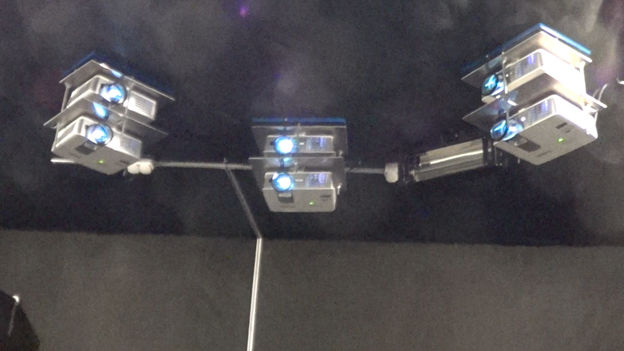
Six-projector system
Therefore, I have developed an optical module for automatic adjustment , naturally adaptable to different screens and lighting:
To create the “non-discontinuity” effect of “neighboring” projectors, a gradient transition is used, damping with the natural logarithm coefficient (of course, through the simplest calculation on a pixel shader of a linearly specified color at a given point). Those. one point has a color (1,1,1), the second (0,0,0). The resulting shader code snippet
Where kj is a parameter selected every time, for each particular projection system and screen, which depends, first of all, on how much black the projector actually has black.
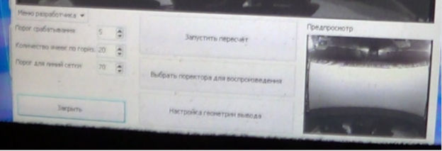
At the bottom there are various settings and a real picture from the camera, at the top, the program itself recognizes the screen and fits into it the setting picture as accurately as possible.
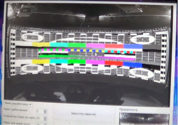
And then it remains only to run the recalculation. Thus, to compare, again, with the help of the camera, the position on the screen inside this adjustment grid and what the projector displays. That is, highlight the individual pixels on the projector and see where they will be on the camera. But highlighting every n pixel is long. In order not to delay recalculation, I print vertical lines first, then horizontal lines with a certain step. And do not forget that the camera in poor lighting conditions is a very inert thing. Therefore, it is also necessary to correctly select the delay between the line output and its scanning.
Some technical details (Delphi). The most important function is the “forest fire” calculation of the screen area on the camera. The user pokes the mouse or (usually) a finger at the touchscreen, thereby setting the starting point. It is important to choose the right lighting for a better screen-non-screen contrast.
After that, you just need to do all the checks for out-of-bounds, and calculate its texture coordinate for each pixel.
Well, now just run the mapping.
Everything. Each pixel of the projector (of those that are possible) is associated with a pixel on the screen.
Now you can enjoy the result.

The image is split due to the stereo image. Glasses are much more interesting. Peresveta information is clearly visible on the camera, as it is on the side. From the platform, and even with glasses, the effect is minimal.
Another part of the video, where the 3D effect is minimal and you can evaluate exactly the reduction.

And a couple of important notes:
First , the output to each projector is necessarily its own stream, with its frame cache and synchronization with vsync. Otherwise, you will have everything or slow down or tear the picture. Especially if the projectors under 12.
Secondly , if you stretch a 4: 3 picture, suppose to 16: 9, but the picture is cartoonish, and the proportions of the objects are not very clear, there will be no big problems. But if you stretch on a cylindrical screen, everything will not be in proportion at all, since there are 21: 9, 27: 9 ratios, etc. But if you show it in proportion to the right one, then it remains to twist 10-12 videos that were created just for such a screen, and forget about the rest.
There is an exit. With the help of the so-called Super zoom, you can leave the central part of the frame practically without distortion, and stretch the edges. Peripheral vision proportions are not so important, and the effect of immersion increases greatly. In this method, of course, there are a lot of minuses, but there are more pluses.
Waiting for a question about a programming language, the interface is written in Delphi, the whole render and platform management is in C ++.
PS: If the topic 5D will be interesting, I can continue the story about the various protocols of various platforms or about the adaptation of ready-made unity virtual reality videos for this industry. Or something else interesting. In general, I am waiting for comments / questions.
So. 5D is primarily a cinema with stereo content. After all, sound or tactile sensations are not as important for most people as the video series.
The following technologies are currently used on the market:
- 2-projector system with linear or circular polarization. The main disadvantage is the frequent burnout of polarizing filters.
- Stereo “homemade” emitter, where for synchronization is used 3-din connector of professional nvidia video cards. The main disadvantage is that the video card with this connector is now practically not available.
- Nvidia 3D vision, where the standard emitter is “hacked” and the synchronization signal is transmitted to another, because the standard is very weak and not stable on a long wire. There are manufacturers who can only install 301 drivers, as further NVIDIA has improved protection. But, for example, we solved this question in a fundamentally different way, so we are not afraid of these security updates.
') - RedPoint sync-based adapter to VGA cable. Where in each non-even frame, a marker is placed at the top in the form of a red dot, so that the adapter recognizes where the frame is even, where it is not. The main disadvantage is VGA with all the resulting picture quality.
- Various multi-projector solutions based on claim 1, item 3 or mono.
And the screens are also different:
- The usual rectangular screen of various proportions (as a rule, to the maximum for the hall, less often adhering to 16: 9 or 4: 3).
- The rectangular main screen and on the sides of 2 non-large screens are also flat.
- Cylindrical screen with approximately equal distance from any point along one horizontal line to the projector (s).
- Various screens of complex shapes: spheres, uneven walls of museums, etc.
And there was a task for the render to work on all systems, OS from win XP to 10, etc. And, most often, this is the old hardware and windows XP. Writing the render itself was not a problem, I had previously developed many cool pieces for ProgDVB, including his, but then there was the problem of mixing multi-projector systems. It is almost impossible to hang 2 different projectors, forcing them to shine at one point. For this, before, special expensive adjusting platforms had to be used, which had to be wound for a long time somewhere under the ceiling in an uncomfortable position, and since it was a mechanic, the projectors could again “disperse” from any more or less strong cotton.
Yes, and with single-projector systems, too, everything is not so smooth. Although the projectors themselves are able to adjust the geometry, they do it too stepwise.
Therefore, a simple grid was taken from the TV channel settings:
That mouse can be distorted like this:
So that both projectors start shining on the screen with corresponding pixels at one point.
But manually reducing 2 projectors on a flat screen is not difficult. Our software also works on more complex systems. Take, for example, a 6-projection system with a cylindrical screen. And since the screen is cylindrical - for each of the 6 parts of the “grid” you need not just linear distortion, but a much more complicated algorithm that is extremely hard and long to manually do.
Six-projector system
Therefore, I have developed an optical module for automatic adjustment , naturally adaptable to different screens and lighting:
To create the “non-discontinuity” effect of “neighboring” projectors, a gradient transition is used, damping with the natural logarithm coefficient (of course, through the simplest calculation on a pixel shader of a linearly specified color at a given point). Those. one point has a color (1,1,1), the second (0,0,0). The resulting shader code snippet
float cc=log(color)*kj; float4 c2=rgb*exp(cc); return c2; Where kj is a parameter selected every time, for each particular projection system and screen, which depends, first of all, on how much black the projector actually has black.
At the bottom there are various settings and a real picture from the camera, at the top, the program itself recognizes the screen and fits into it the setting picture as accurately as possible.
And then it remains only to run the recalculation. Thus, to compare, again, with the help of the camera, the position on the screen inside this adjustment grid and what the projector displays. That is, highlight the individual pixels on the projector and see where they will be on the camera. But highlighting every n pixel is long. In order not to delay recalculation, I print vertical lines first, then horizontal lines with a certain step. And do not forget that the camera in poor lighting conditions is a very inert thing. Therefore, it is also necessary to correctly select the delay between the line output and its scanning.
Some technical details (Delphi). The most important function is the “forest fire” calculation of the screen area on the camera. The user pokes the mouse or (usually) a finger at the touchscreen, thereby setting the starting point. It is important to choose the right lighting for a better screen-non-screen contrast.
Data preparation
Then we simply transform this set of pixels into a region, in which we will look for lines later.
procedure TCam_Geometry_frm.CalcPixelRegion(x,y:integer); var StartP:TPoint; I: Integer; J: Integer; StaPo,EnPo:integer; begin StartP.X := x * InternalBitmap.Width div Image1.Width; StartP.Y := y * InternalBitmap.Height div Image1.Height; SetLength(CheckingMask,InternalBitmap.Height); for I := 0 to InternalBitmap.Height - 1 do begin SetLength(CheckingMask[i],InternalBitmap.Width); for J := 0 to InternalBitmap.Width-1 do begin CheckingMask[i][j].IsCheckPoint := false; CheckingMask[i][j].IsPointChecked := false; CheckingMask[i][j].typ := 0; CheckingMask[i][j].texX := -1; CheckingMask[i][j].texY := -1; end; end; SetLength(TempFireBuf,InternalBitmap.Width * InternalBitmap.Height * 4); StaPo := 0; EnPo := 1; TempFireBuf[0].XPos := StartP.X; TempFireBuf[0].YPos := StartP.Y; CheckingMask[StartP.Y][StartP.X].IsPointChecked := true; CheckingMask[StartP.Y][StartP.X].IsCheckPoint := true; while StaPo <> EnPo do begin if (abs(InternalPic.GetRED(TempFireBuf[StaPo].XPos, TempFireBuf[StaPo].YPos)- InternalPic.GetRED(TempFireBuf[TempFireBuf[StaPo].pripos].XPos, TempFireBuf[TempFireBuf[StaPo].pripos].YPos))<SpinEdit1.Value) and (abs(InternalPic.GetGreen(TempFireBuf[StaPo].XPos, TempFireBuf[StaPo].YPos)-InternalPic.GetGreen(TempFireBuf[TempFireBuf[StaPo].pripos].XPos, TempFireBuf[TempFireBuf[StaPo].pripos].YPos))<SpinEdit1.Value) and (abs(InternalPic.GetBlue(TempFireBuf[StaPo].XPos, TempFireBuf[StaPo].YPos)-InternalPic.GetBlue(TempFireBuf[TempFireBuf[StaPo].pripos].XPos, TempFireBuf[TempFireBuf[StaPo].pripos].YPos))<SpinEdit1.Value) then begin CheckingMask[TempFireBuf[StaPo].YPos][TempFireBuf[StaPo].XPos].IsCheckPoint := true; if TempFireBuf[StaPo].XPos > 0 then begin if not CheckingMask[TempFireBuf[StaPo].YPos][TempFireBuf[StaPo].XPos-1].IsPointChecked then begin TempFireBuf[EnPo].XPos := TempFireBuf[StaPo].XPos-1; TempFireBuf[EnPo].YPos := TempFireBuf[StaPo].YPos; TempFireBuf[EnPo].pripos := StaPo; CheckingMask[TempFireBuf[EnPo].YPos][TempFireBuf[EnPo].XPos].IsPointChecked := true; inc(EnPo); end; end; if TempFireBuf[StaPo].XPos < InternalBitmap.Width - 1 then begin if not CheckingMask[TempFireBuf[StaPo].YPos][TempFireBuf[StaPo].XPos+1].IsPointChecked then begin TempFireBuf[EnPo].XPos := TempFireBuf[StaPo].XPos+1; TempFireBuf[EnPo].YPos := TempFireBuf[StaPo].YPos; TempFireBuf[EnPo].pripos := StaPo; CheckingMask[TempFireBuf[EnPo].YPos][TempFireBuf[EnPo].XPos].IsPointChecked := true; inc(EnPo); end; end; if TempFireBuf[StaPo].YPos > 0 then begin if not CheckingMask[TempFireBuf[StaPo].YPos-1][TempFireBuf[StaPo].XPos].IsPointChecked then begin TempFireBuf[EnPo].XPos := TempFireBuf[StaPo].XPos; TempFireBuf[EnPo].YPos := TempFireBuf[StaPo].YPos-1; TempFireBuf[EnPo].pripos := StaPo; CheckingMask[TempFireBuf[EnPo].YPos][TempFireBuf[EnPo].XPos].IsPointChecked := true; inc(EnPo); end; end; if (TempFireBuf[StaPo].YPos < 5) or (TempFireBuf[StaPo].YPos < 5) then begin ShowMessage(' . .'); exit; end; if TempFireBuf[StaPo].YPos < InternalBitmap.Height - 1 then begin if not CheckingMask[TempFireBuf[StaPo].YPos+1][TempFireBuf[StaPo].XPos].IsPointChecked then begin TempFireBuf[EnPo].XPos := TempFireBuf[StaPo].XPos; TempFireBuf[EnPo].YPos := TempFireBuf[StaPo].YPos+1; TempFireBuf[EnPo].pripos := StaPo; CheckingMask[TempFireBuf[EnPo].YPos][TempFireBuf[EnPo].XPos].IsPointChecked := true; inc(EnPo); end; end; end; inc(StaPo); end; SetLength(TempFireBuf,0); end; Then we simply transform this set of pixels into a region, in which we will look for lines later.
procedure TCam_Geometry_frm.CreateFrame; var nn:array [1..10] of integer; i,j,k,l,tmp:integer; rasts:array [1..4]of extended; rad:extended; begin for I := 1 to 10 do nn[i] := GetMinY(i); for k := 0 to 5 do for I := 11 to InternalPic.PicX - 1 do begin if (nn[1] > 0) and (nn[5] > 0) and (nn[10] > 0) and (abs(nn[10]-nn[1])< 7) then begin tmp := 0; for l := 1 to 10 do tmp := tmp + nn[l]; tmp := tmp div 10; while nn[5] < tmp do begin CheckingMask[nn[5]][i-6].IsCheckPoint := false; inc(nn[5]); end; while nn[5] > tmp do begin CheckingMask[nn[5]][i-6].IsCheckPoint := true; dec(nn[5]); end; end; for j := 2 to 10 do nn[j-1] := nn[j]; nn[10] := GetMinY(i); end; for I := 1 to 10 do nn[i] := GetMaxY(i); for k := 0 to 5 do for I := 11 to InternalPic.PicX - 1 do begin if (nn[1] > 0) and (nn[5] > 0) and (nn[10] > 0) and (abs(nn[10]-nn[1])< 7) then begin tmp := 0; for l := 1 to 10 do tmp := tmp + nn[l]; tmp := tmp div 10; while nn[5] <= tmp do begin CheckingMask[nn[5]][i-6].IsCheckPoint := false; inc(nn[5]); end; while nn[5] > tmp do begin CheckingMask[nn[5]][i-6].IsCheckPoint := true; dec(nn[5]); end; end; for j := 2 to 10 do nn[j-1] := nn[j]; nn[10] := GetMaxY(i); end; rasts[1] := 0;rasts[2] := 0;rasts[3] := 0;rasts[4] := 0; Center.X := 0;Center.Y := 0; k := 0; for I := 11 to InternalPic.PicY - 1 do for J := 11 to InternalPic.PicX - 1 do if CheckingMask[i][j].IsCheckPoint then begin Center.X := Center.X + J; Center.Y := Center.Y + I; inc(k); end; Center.X := Center.X div k; Center.Y := Center.Y div k; for I := 11 to InternalPic.PicY - 1 do for J := 11 to InternalPic.PicX - 1 do begin if CheckingMask[i][j].IsCheckPoint then begin rad := (J-Center.X)*(J-Center.X)+(I-Center.Y)*(I-Center.Y); if i < Center.Y then begin if j < Center.X then begin if (rasts[1] < rad) then begin rasts[1] := rad; X1Y1.X := J; X1Y1.Y := I; end; end else begin if (rasts[2] < rad) then begin rasts[2] := rad; X2Y1.X := J; X2Y1.Y := I; end; end; end else begin if j < Center.X then begin if (rasts[3] < rad) then begin rasts[3] := rad; X1Y2.X := J; X1Y2.Y := I; end; end else begin if (rasts[4] < rad) then begin rasts[4] := rad; X2Y2.X := J; X2Y2.Y := I; end; end; end; end; end; LeftSetkaSide.IsHorisontOnScreen := false; LeftSetkaSide.CoordVal := 0; LeftSetkaSide.IsHorisontVals := false; LeftSetkaSide.x[1] := X1Y1.X; LeftSetkaSide.y[1] := X1Y1.Y; LeftSetkaSide.x[2] := X1Y2.X; LeftSetkaSide.y[2] := X1Y2.Y; LeftSetkaSide.y[3] := (LeftSetkaSide.y[1]+LeftSetkaSide.y[2]) / 2; LeftSetkaSide.x[3] := GetMinX(Round(LeftSetkaSide.y[3])); LeftSetkaSide.y[4] := (LeftSetkaSide.y[1] + LeftSetkaSide.y[3]) / 2; LeftSetkaSide.x[4] := GetMinX(Round(LeftSetkaSide.y[4])); LeftSetkaSide.y[5] := (LeftSetkaSide.y[2] + LeftSetkaSide.y[3]) / 2; LeftSetkaSide.x[5] := GetMinX(Round(LeftSetkaSide.y[5])); RightSetkaSide.IsHorisontOnScreen := false; RightSetkaSide.CoordVal := 0; RightSetkaSide.IsHorisontVals := false; RightSetkaSide.x[1] := X2Y1.X; RightSetkaSide.y[1] := X2Y1.Y; RightSetkaSide.x[2] := X2Y2.X; RightSetkaSide.y[2] := X2Y2.Y; RightSetkaSide.y[3] := (RightSetkaSide.y[1]+RightSetkaSide.y[2]) / 2; RightSetkaSide.x[3] := GetMaxX(Round(RightSetkaSide.y[3])); RightSetkaSide.y[4] := (RightSetkaSide.y[1] + RightSetkaSide.y[3]) / 2; RightSetkaSide.x[4] := GetMaxX(Round(RightSetkaSide.y[4])); RightSetkaSide.y[5] := (RightSetkaSide.y[2] + RightSetkaSide.y[3]) / 2; RightSetkaSide.x[5] := GetMaxX(Round(RightSetkaSide.y[5])); UpSetkaSide.IsHorisontOnScreen := true; UpSetkaSide.CoordVal := 0; UpSetkaSide.IsHorisontVals := false; UpSetkaSide.x[1] := X1Y1.X; UpSetkaSide.y[1] := X1Y1.Y; UpSetkaSide.x[2] := X2Y1.X; UpSetkaSide.y[2] := X2Y1.Y; UpSetkaSide.x[3] := (UpSetkaSide.x[1]+UpSetkaSide.x[2]) / 2; UpSetkaSide.y[3] := GetMinY(Round(UpSetkaSide.x[3])); UpSetkaSide.x[4] := (UpSetkaSide.x[1]+UpSetkaSide.x[3]) / 2; UpSetkaSide.y[4] := GetMinY(Round(UpSetkaSide.x[4])); UpSetkaSide.x[5] := (UpSetkaSide.x[2]+UpSetkaSide.x[3]) / 2; UpSetkaSide.y[5] := GetMinY(Round(UpSetkaSide.x[5])); DownSetkaSide.IsHorisontOnScreen := true; DownSetkaSide.CoordVal := 0; DownSetkaSide.IsHorisontVals := false; DownSetkaSide.x[1] := X1Y2.X; DownSetkaSide.y[1] := X1Y2.Y; DownSetkaSide.x[2] := X2Y2.X; DownSetkaSide.y[2] := X2Y2.Y; DownSetkaSide.x[3] := (DownSetkaSide.x[1]+DownSetkaSide.x[2]) / 2; DownSetkaSide.y[3] := GetMaxY(Round(DownSetkaSide.x[3])); DownSetkaSide.x[4] := (DownSetkaSide.x[1]+DownSetkaSide.x[3]) / 2; DownSetkaSide.y[4] := GetMaxY(Round(DownSetkaSide.x[4])); DownSetkaSide.x[5] := (DownSetkaSide.x[2]+DownSetkaSide.x[3]) / 2; DownSetkaSide.y[5] := GetMaxY(Round(DownSetkaSide.x[5])); end; After that, you just need to do all the checks for out-of-bounds, and calculate its texture coordinate for each pixel.
Well, now just run the mapping.
The main algorithm for calculating
It is applied like this:
procedure TCam_Geometry_frm.AddLograngeKoeffs(n:integer;byX:boolean;coord:integer); var I, J: integer; possx,possy,ccou:integer; srX1,srY1:extended; lfid:integer; foundPoints:arrpo; Center:TPoint; Clct,Clct2,Clct3,last:TPoint; dy,sry,ddy,y:extended; // CheAr:array of array of boolean; begin possx := 0; possy := 0; ccou := 0; SetLength(foundPoints,0); for I := 0 to Length(ProjSetka[n]) - 1 do for J := 0 to Length(ProjSetka[n][i]) - 1 do begin if (byX and (ProjSetka[n][i][j].ProjX = coord) and IsPossHere(n,j,i,byX,20, 20,srX1,srY1))or ((not byX) and (ProjSetka[n][i][j].ProjY = coord) and IsPossHere(n,j,i,byX,20, 20,srX1,srY1))then begin possx := possx + j; possy := possy + i; inc(ccou); SetLength(foundPoints,ccou); foundPoints[ccou-1].X := J; foundPoints[ccou-1].Y := I; end; end; if ccou < 10 then begin possx := -3; exit; end; possx := possx div ccou; possy := possy div ccou; Center.X := possx; Center.Y := possy; lfid := length(LograngeFuncs[n]); SetLength(LograngeFuncs[n],length(LograngeFuncs[n])+1); LograngeFuncs[n][lfid].IsHorisontOnScreen := false; LograngeFuncs[n][lfid].CoordVal := coord; LograngeFuncs[n][lfid].IsHorisontVals := byX; i := GetMinLengthFromArr(foundPoints,Center); if i < 0 then begin ShowMessage(' !'); exit; end; IsPossHere(n,foundPoints[i].X,foundPoints[i].Y,byX,20, 20,srX1,srY1); LograngeFuncs[n][lfid].x[1] := srX1; LograngeFuncs[n][lfid].Y[1] := srY1; foundPoints[i].X := -1; i := GetMaxLengthFromArr(foundPoints,Center); IsPossHere(n,foundPoints[i].X,foundPoints[i].Y,byX,20, 20,srX1,srY1); LograngeFuncs[n][lfid].x[5] := srX1; LograngeFuncs[n][lfid].Y[5] := srY1; foundPoints[i].X := -1; Clct.X := round(srX1); Clct.Y := round(srY1); i := GetMaxLengthFromArr(foundPoints,Center); while abs(GetAngleFrom3Points(Center,Clct,foundPoints[i])) < Pi / 2 do begin foundPoints[i].X := -1; i := GetMaxLengthFromArr(foundPoints,Center); if i < 0 then begin ShowMessage(' !'); exit; end; end; IsPossHere(n,foundPoints[i].X,foundPoints[i].Y,byX,20, 20,srX1,srY1); LograngeFuncs[n][lfid].x[4] := srX1; LograngeFuncs[n][lfid].Y[4] := srY1; Clct2.X := round(srX1); Clct2.Y := round(srY1); LograngeFuncs[n][lfid].x[2] := -1; LograngeFuncs[n][lfid].x[3] := -1; while (LograngeFuncs[n][lfid].x[2] < 0) or (LograngeFuncs[n][lfid].x[3] < 0) do begin i := GetNearestFromArr(foundPoints,Center,min(GetLengthBW2P(Center,Clct),GetLengthBW2P(Center,Clct2)) div 2); if LograngeFuncs[n][lfid].x[2] < 0 then begin IsPossHere(n,foundPoints[i].X,foundPoints[i].Y,byX,20, 20,srX1,srY1); LograngeFuncs[n][lfid].x[2] := srX1; LograngeFuncs[n][lfid].Y[2] := srY1; foundPoints[i].X := -1; Clct3.X := round(srX1); Clct3.Y := round(srY1); end else begin if i < 0 then begin LograngeFuncs[n][lfid].x[3] := last.X; LograngeFuncs[n][lfid].Y[3] := last.Y; end else if abs(GetAngleFrom3Points(Center,Clct3,foundPoints[i])) > Pi / 2 then begin IsPossHere(n,foundPoints[i].X,foundPoints[i].Y,byX,20, 20,srX1,srY1); LograngeFuncs[n][lfid].x[3] := srX1; LograngeFuncs[n][lfid].Y[3] := srY1; end; end; if i >= 0 then begin last := foundPoints[i]; foundPoints[i].X := -1; end; end; if abs(LograngeFuncs[n][lfid].x[1]-LograngeFuncs[n][lfid].x[5]) > abs(LograngeFuncs[n][lfid].y[1]-LograngeFuncs[n][lfid].y[5]) then begin LograngeFuncs[n][lfid].IsHorisontOnScreen := true; end else LograngeFuncs[n][lfid].IsHorisontOnScreen := false; if LograngeFuncs[n][lfid].IsHorisontOnScreen then begin sry := 0; for I := 1 to 5 do sry := sry + LograngeFuncs[n][lfid].y[i]; sry := sry / 5; dy := 0; for I := 1 to 5 do if dy < abs(sry - LograngeFuncs[n][lfid].y[i]) then dy := abs(sry - LograngeFuncs[n][lfid].y[i]); dy := dy * 3 + 5; for I := 10 to 1000 do begin y := CalcPointByPolinom(n,lfid,i,-1); if (y > 0) and(dy < abs(sry - y)) then begin SetLength(LograngeFuncs[n],length(LograngeFuncs[n])-1); exit; end; end; end else begin sry := 0; for I := 1 to 5 do sry := sry + LograngeFuncs[n][lfid].x[i]; sry := sry / 5; dy := 0; for I := 1 to 5 do if dy < abs(sry - LograngeFuncs[n][lfid].x[i]) then dy := abs(sry - LograngeFuncs[n][lfid].x[i]); dy := dy * 3+5; for I := 10 to 1000 do begin y := CalcPointByPolinom(n,lfid,-1,i); if (y > 0) and(dy < abs(sry - y)) then begin SetLength(LograngeFuncs[n],length(LograngeFuncs[n])-1); exit; end; end; end; end; It is applied like this:
procedure TCam_Geometry_frm.sButton3Click(Sender: TObject); var I, couu: Integer; geom_frms:array of Tcam_geomery_lines_ouput_frm; j,l: Integer; k, pos: Integer; begin if not sButton1.Enabled then begin FlagStop:=true;exit;end; FlagStop:=false; SetLength(geom_frms,g_MonitorsCount); SetLength(ProjSetka,g_MonitorsCount); SetLength(LograngeFuncs,g_MonitorsCount); for I := 0 to g_MonitorsCount-1 do begin geom_frms[i] := Tcam_geomery_lines_ouput_frm.Create(self); geom_frms[i].PosX := g_MonitorsSetup[i+1].ScreenPosition.x; geom_frms[i].PosY := g_MonitorsSetup[i+1].ScreenPosition.y; Application.ProcessMessages; SetLength(ProjSetka[i],length(CheckingMask)); SetLength(LograngeFuncs[i],0); for J := 0 to length(CheckingMask)-1 do begin SetLength(ProjSetka[i][j],length(CheckingMask[j])); for k := 0 to length(CheckingMask[j]) - 1 do begin ProjSetka[i][j][k].ProjX := -1; ProjSetka[i][j][k].ProjY:= -1; end; end; end; sButton2.Enabled := false; sButton1.Enabled := false; sButton17.Enabled := false; sButton4.Enabled := false; sButton5.Enabled := false; for I := 0 to g_MonitorsCount-1 do begin geom_frms[i].Show; geom_frms[i].SetBlack; end; for L := 0 to 40 do begin Application.ProcessMessages; Sleep(20); end; GetBitmapFromCam(blackBitmap); InitPicBuffer(blackPic,blackBitmap.Width,blackBitmap.Height); CopyToPic(blackBitmap,0,0,blackPic); for I := 0 to g_MonitorsCount-1 do begin for L := 0 to 70 do begin Application.ProcessMessages; Sleep(20); end; GetBitmapFromCam(blackBitmap); CopyToPic(blackBitmap,0,0,blackPic); couu := 16; if FlagStop then break; for j := 0 to couu do begin pos := j*geom_frms[i].Width div couu; if pos < 4 then pos := 4; if pos >= geom_frms[i].Width - 4 then pos := geom_frms[i].Width - 4; geom_frms[i].PaintLine(pos,0,pos,geom_frms[i].Height); for L := 0 to 70 do begin Application.ProcessMessages; Sleep(20); end; if not SaveProjLineCoords(i,pos,-1) then FlagStop := true; AddLograngeKoeffs(i,true,pos); pos := j*geom_frms[i].Height div couu; if pos < 4 then pos := 4; if pos >= geom_frms[i].Height - 4 then pos := geom_frms[i].Height - 4; geom_frms[i].PaintLine(0,pos,geom_frms[i].Width,pos); for L := 0 to 70 do begin Application.ProcessMessages; Sleep(20); end; if not SaveProjLineCoords(i,-1,pos) then FlagStop := true; AddLograngeKoeffs(i,false,pos); if FlagStop then break; end; geom_frms[i].SetBlack; // geom_frms[i].hide; SaveProjSsetka(i); end; if not FlagStop then SetCaptSetkaWidthToOne; if not FlagStop then CreateProjSetka; for I := 0 to g_MonitorsCount-1 do begin geom_frms[i].Free; end; if not FlagStop then SaveGeometry; sButton2.Enabled := true; sButton1.Enabled := true; sButton17.Enabled := true; sButton4.Enabled := true; sButton5.Enabled := true; end; Everything. Each pixel of the projector (of those that are possible) is associated with a pixel on the screen.
Now you can enjoy the result.
The image is split due to the stereo image. Glasses are much more interesting. Peresveta information is clearly visible on the camera, as it is on the side. From the platform, and even with glasses, the effect is minimal.
Another part of the video, where the 3D effect is minimal and you can evaluate exactly the reduction.
And a couple of important notes:
First , the output to each projector is necessarily its own stream, with its frame cache and synchronization with vsync. Otherwise, you will have everything or slow down or tear the picture. Especially if the projectors under 12.
Secondly , if you stretch a 4: 3 picture, suppose to 16: 9, but the picture is cartoonish, and the proportions of the objects are not very clear, there will be no big problems. But if you stretch on a cylindrical screen, everything will not be in proportion at all, since there are 21: 9, 27: 9 ratios, etc. But if you show it in proportion to the right one, then it remains to twist 10-12 videos that were created just for such a screen, and forget about the rest.
There is an exit. With the help of the so-called Super zoom, you can leave the central part of the frame practically without distortion, and stretch the edges. Peripheral vision proportions are not so important, and the effect of immersion increases greatly. In this method, of course, there are a lot of minuses, but there are more pluses.
Waiting for a question about a programming language, the interface is written in Delphi, the whole render and platform management is in C ++.
PS: If the topic 5D will be interesting, I can continue the story about the various protocols of various platforms or about the adaptation of ready-made unity virtual reality videos for this industry. Or something else interesting. In general, I am waiting for comments / questions.
Source: https://habr.com/ru/post/333652/
All Articles