Creating Shaders
To master the creation of graphic shaders is to take control of the full power of the video processor with its thousands of parallel cores. This way of programming requires a different way of thinking, but revealing its potential is worth the effort.
Virtually any modern graphic simulation uses code written for a video processor: from realistic lighting effects in high-tech AAA games to two-dimensional post-processing effects and fluid simulation.

Scene from Minecraft, before and after the addition of several shaders .
')
Sometimes shader programming is mysterious black magic and is often misunderstood. There are many examples of code that demonstrate the creation of incredible effects, but in which there are practically no explanations. In my guide, I want to fill this gap. I will focus mainly on the basic principles of creating and understanding shader code so that you can easily customize, combine or write your own shaders from scratch!
This is a general guide, so everything studied in it can be applied in any technology that uses shaders.
A shader is simply a program running in the graphics pipeline. It tells the computer how to render each pixel. These programs are called shaders (“shaders”), because they are often used to control lighting and shading effects, but nothing prevents them from being used for other special effects.
Shaders are written in a special shader language. Do not worry, you will not have to learn a completely new language: we will use GLSL (OpenGL Shading Language), which is similar to C. (There are several shader languages for different platforms, but since they are all adapted to run in a video processor, they are similar to friend.)
Note: This article is devoted exclusively to fragment shaders. If you're curious about what other types of shaders are, you can read about the different stages of the graphics pipeline in the OpenGL Wiki.
In this tutorial we will use ShaderToy . It allows us to start programming shaders right in the browser, without fussing with the installation and configuration! (For rendering, it uses WebGL, so a browser with the support of this technology is required.) Creating an account is not necessary, but convenient for saving code.
Note: at the time of writing, ShaderToy was in beta state [approx. per .: article written in 2015] . Some interface / syntax details may be slightly different.
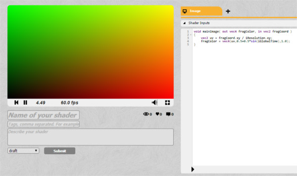
By clicking on the New Shader , you will see something like this:
If you are not registered, the interface may be slightly different.
The small black arrow below serves to compile the code.
I am going to describe how shaders work in one sentence. Are you ready? Here it is!
The sole purpose of the shader is to return four numbers:
This is the only shader that can do. The function is performed for each pixel on the screen. It returns these four color values, which become the color of a pixel. This is what is called a pixel shader (sometimes called a fragment shader ).
With this in mind, let's fill the screen with a solid red. The RGBA values (red, green, blue and alpha, which defines transparency) vary from
Congratulations! Here is your first ready shader!
Task: Try changing color to solid gray.
It does not look very inspiring. We have the power to execute code for hundreds of thousands of pixels simultaneously, and we paint them in one color.
Let's try to render a gradient on the screen. We will not be able to achieve much without knowing a couple of things about the pixels that we influence, for example, their position on the screen ...
The pixel shader passes several variables that we can use. The most useful is
Note: You can access the components of any
Have you noticed the problem in the above code? Try clicking on the go fullscreen button in the lower right corner of the preview window.
The sizes of the red part of the screen will be different and depend on the size of the screen. To paint in red exactly half the screen, we need to know its size. Screen size is not a built-in variable, like pixel position, because it is usually chosen by the programmer who creates the application. In our case, the screen size is set by the ShaderToy developers.
If something is not a built-in variable, then you can send this information from the CPU (from the main program) to the video processor (to your shader). ShaderToy takes on this task. All variables transmitted to the shader are indicated in the Shader Inputs tab. Variables transmitted in this way from the CPU to the video processor are called in the GLSL uniform (global) .

Let's change the code to correctly determine the center of the screen. We need to use the input data of the
If you try now to resize the preview window, the colors should accurately split the screen in half.
Turning it into a gradient is pretty easy. The color values vary from
Voila!
Task: Can you turn this image into a vertical gradient? What about the diagonal? What about a gradient of several colors?
If you experiment with the code, you will notice that the upper left corner has coordinates
Experimenting with colors is interesting, but if we want to do something impressive, then our shader has to learn how to get an image as input and change it. In this way, you can get a shader that affects the entire game screen (for example, an “underwater” effect or color correction), or only affect certain objects (for example, to create a realistic lighting system).
If we were programming on a conventional platform, then we would have to transfer the image (or texture) as uniform to the video processor, just as we would transfer the screen resolution. ShaderToy will take care of this for us. At the bottom of the screen there are four input channels:
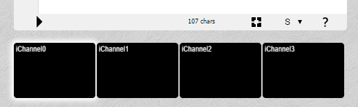
Four input channels ShaderToy
Click on iChannel0 and select any texture (image).
As a result, you will have an image transmitted to the shader. However, there is one problem: the lack of the
If we can only return the color, how can we draw the texture on the screen? We need to somehow bind the current pixel of the shader to the corresponding pixel of the texture:

Depending on the location (0,0), it may be necessary to reflect the Y-axis on the screen to properly bind the texture. At the time of writing, the ShaderToy has been updated and the starting point is in the upper left corner, so nothing needs to be reflected.
We can bind using the
You can snap the coordinates to the screen as you like. You can draw the entire texture on a quarter of the screen (skipping pixels, that is, reducing its scale) or simply draw a part of the texture.
We only want to see the image, so the pixels will match on a 1: 1 scale:
So we got our first image!
Now, having learned how to correctly obtain data from a texture, we can do anything with it! We can stretch or scale them, experiment with colors.
Let's try to put a gradient on the image, similar to what we did before:
Congratulations, you just wrote your first post-processing effect!
Task: Can you write a shader that makes an image in black and white?
Please note that although we have chosen a static image, everything that you see is performed in real time. To see this, replace the static image with the video: click on iChannel0 and select any video.
So far, all our effects have been static. We can do much more interesting things by using the input data provided by ShaderToy.
GLSL has built-in sine and cosine functions, as well as many other useful functions, such as getting the length of a vector or the distance between two vectors. Color values cannot be negative, so you need to get an absolute value using the
Task: Can you make a shader that changes the image from black and white to color and back?
When debugging code, you can execute it step by step or print values, but this is not possible when writing shaders. You can search for debugging tools for your platform, but in general, it is best to link the value to be checked to some graphical information that can be seen.
These are just the basics of working with shaders, but by becoming familiar with them, you can achieve much more. See ShaderToy effects and see if you can understand or play them!
In this tutorial, I did not mention the Vertex Shaders (Vertex Shaders) . They are written in the same language, but they are executed for each vertex, not a pixel, and return with the color also the position. Vertex shaders typically project a 3D scene onto a screen (this feature is built into most graphics pipelines). Pixel shaders provide most of the complex effects seen on the screen, so I’m looking at them.
Another task: Can you write a shader that removes the green color from the video from ShaderToy and adds another video as the background of the first video?
ShaderToy , with which we worked earlier, is great for quick testing and experiments, but its capabilities are rather limited. For example, you can not control the data transmitted to the shader. If we have our own environment for running shaders, we can create all sorts of interesting effects and use them in our own projects! To run shaders in the browser, we will use the Three.js framework. WebGL is a Javascript API that allows rendering of shaders. Three.js is needed only to simplify the work.
If you are not interested in JavaScript or a web platform, do not worry, we will not go into the features of web rendering (but if you want to learn more about the framework, then learn this tutorial ). Setting up shaders in the browser is the fastest way to get started, but by becoming familiar with this process, you can easily set up and use shaders on any platform.
In this section, we will look at local shader configuration. You can repeat after me without having to download something thanks to this built-in widget CodePen :
You can create a fork and edit the project on CodePen.
Three.js is a JavaScript framework that takes over most of the boilerplate code for WebGL needed to render shaders. The easiest way to start is to use the version laid out on the CDN .
You can download an HTML file that is a simple Threejs scene.
Save the file to disk and open it in the browser. You should see a black screen. It's not very interesting so far, so let's try to add a cube, just to check that everything works.
To create a cube, we need to define its geometry and material, and then add it to the scene. Add this code snippet to the
We will not consider the cube in detail, because we are more interested in the shader. But if everything is done correctly, then you will see a green cube in the center of the screen:

While we are here, let's make it rotate. The
Task: Can you rotate the cube along a different axis? What about two axes at the same time?
So, everything is ready, it's time to add shaders!
At this stage we can start thinking about the implementation process of the shaders. Most likely, you will have a similar situation regardless of the platform: everything is set up, objects are drawn on the screen, so how do you get access to the video processor now?
To create a scene, we use JavaScript. In other situations, C ++, Lua or any other language can be used. Regardless, shaders are written in a special shader language . The OpenGL shader language is called GLSL (Open GL S hading L anguage). Since we use WebGL based on OpenGL, we will write on GLSL.
How and where is GLSL code written? The main rule: the GLSL code is loaded as a
In JavaScript, this can be done by simply passing the code inside a variable, like this:
This will work, but since there are no easy ways to create multi-line strings in JavaScript, this is not very convenient for us. Most programmers write shader code in text files and give them the extension
This is possible, but in this tutorial we will write the shader code inside the new
Create a new
We will assign him ID
Now let's insert a very simple shader that returns white.
(The
Now we need to download this code. We will do this in a simple JavaScript line that finds the HTML element and retrieves the inner text:
It must be under the cube code.
Do not forget: only the code loaded as a string will be parsed as a valid GLSL code (that is,
You can create a fork and edit the project on CodePen.
The methods of using the shader may vary, they depend on the platform used and its interface with the video processor. There are never any difficulties with this, and a quick search can figure out how to create an object and apply shaders to it using Three.js .
We need to create a special material and pass it to the shader code. We will create a plane as a shader object (but we can also use a cube). Here is what you need to do:
At this point, you should see a white screen:
You can create a fork and edit the project on CodePen.
If you replace the color in the shader code with another one and refresh the page, you will see a new color.
Task: Can you make one part of the screen red and the other blue? (If it doesn't work out, then in the next step I will give a hint!)
At this point, we can already do anything with the shader, but do not yet know what can be done. We only have the built-in ability to determine the position of the pixel
To transfer data to the shader, we need to send what we call a uniform variable. To do this, we create an
Each uniform must have a
To send it to the shader, modify the ShaderMaterial instance
We haven't finished yet! Now that the shader gets this variable, we need to do something with it. Let's create a gradient like we did before: normalizing the coordinate and using it to create a color value.
Change the shader code as follows:
As a result, we get a beautiful gradient!
You can create a fork and edit the project on CodePen.
Task: Try to divide the screen into four equal parts of different colors. Like this:
It's good that we learned to send data to the shader, but what if we need to update them? For example, if you open the previous example in a new tab , and then resize the window, the gradient will not be updated, because it uses the old screen sizes.
To update the variables usually just re-send the uniform variable. However, in Three.js, it is enough just to update the
Here's what the rendering function looks like after making changes:
If you open a new CodePen and resize the window, you will see how the colors change, despite the fact that the original size of the viewing window remains the same). The easiest way to notice this is by looking at the colors in the corners and making sure that they do not change.
Note: Sending data to a video processor is usually a costly task. Sending several variables in one frame is quite normal, but when hundreds of variables are transmitted per frame, the frame rate will drop significantly. It seems that this is unlikely, but if there are several hundred objects on the screen, and lighting with different properties is applied to all of them, then everything quickly goes out of control. Later we will learn about shader optimization.
Task: Try gradually changing colors.
Regardless of the method of loading and the format of textures on all platforms, they are transmitted to the shader as uniform variables.
A quick note about uploading files to JavaScript: you can easily upload images from an external URL (this is how we will do it). However, if you want to upload an image locally, you will encounter permissions problems, because JavaScript usually cannot and should not have access to files in the system. The easiest way to solve this is to start a local Python server , which is actually easier than it sounds.
In Three.js there is a small convenient function for loading an image as a texture:
The first line is given only once. You can paste any image URL into it.
Then we need to add a texture to the object
And finally, we need to declare a uniform variable in the shader code, and then draw it in the same way as we did before - using the function
A stretched candy image should appear on the screen:
(This is a standard test image in computer graphics, it is taken from the Signal and Image Processing Institute (SIPI) (therefore it shows the abbreviation IPI) University of Southern California. I think it suits us, because we are just studying graphic shaders!)
Task : Try gradually changing texture colors from full color to grayscale.
There is nothing special about the plane we created. We could apply a shader to the cube. In fact, you can simply replace the line with the geometry of the plane:
on:
Voila, candy painted on a cube:
You can argue: “Wait, but this is not like the correct projection of the texture on the cube!” You are right: if you look at the shader, you can see that we are actually telling him “place all the pixels of this image on the screen”. The fact that they are on a cube simply means that all pixels outside of it are discarded.
If we wanted to apply the texture so that it looked physically painted on a cube, then our work would resemble the invention of the 3D engine again (which would be pretty stupid, considering that we already use the 3D engine and we can just ask itdraw the texture separately on each side). In this tutorial we use shaders for what would otherwise be impossible to achieve, so we will not go into such details. (If you want to learn more, Udacity has a great course on the basics of 3D graphics !)
At this stage, we can already do everything that we did in ShaderToy, but now we are able to use any textures and any objects on any platform.
With all this freedom, we can do something like a lighting system, with realistic shadows and light sources. This we will do below. In addition, I will talk about shader optimization techniques.
Having mastered the basics of shaders, we will practically apply the power of the video processor to create realistic dynamic lighting.
From this point on, we will consider general concepts of graphic shaders without reference to a specific platform. (For convenience, all code examples will still use JavaScript / WebGL.)
First, find a suitable way for you to perform shaders. (JavaScript / WebGL is the easiest way, but I recommend you experiment with your favorite platform!)
By the end of this tutorial, you will not only begin to be well versed in lighting systems, but also create your own from scratch.
Here’s what the end result will look like (click the mouse to turn on the light):
Many game engines have ready-made lighting systems, but an understanding of how they are made and how to create your own gives you more opportunities to give the game a unique look. In addition, the shader effects do not have to be only “cosmetic”, they open the doors to stunning new game mechanics!
An excellent example of this is Chroma . The player can run on dynamic shadows created in real time:
We will miss a lot in the initial setup, because it is discussed in detail above. Let's start with a simple fragmentary shader rendering our texture:
There is nothing complicated going on here. The JavaScript code sets the scene and sends the shader the texture for rendering and screen sizes.
In the GLSL code, we declare and use these uniform variables:
Before using pixel coordinates for texture drawing, we normalize them.
Just to make sure you understand everything, here’s a small warm-up task for you:
Task: Render the texture without changing its aspect ratio (Try it yourself, we will look at the solution below.)
It’s pretty obvious why the texture is stretched, but if it’s not clear then here’s a hint: look at the line where we normalize the coordinates:
We divide
We divide x and y into different numbers (by the width and height of the screen). Naturally, the image will be stretched.
What happens if we divide x and y
For the sake of simplicity, in the tutorial we will leave the normalized code the same, it would be nice to figure out what is happening here.
Before you create something interesting, we need a light source. The “light source” is simply a point transmitted to the shader. For this point we will create a new uniform:
We have created a vector with three dimensions, because we want to use
Let's assign JavaScript values to our light source:
We will use the radius as a percentage of the screen size, so it
To get the mouse position, you just need to add an event receiver (event listener ):
Let's now write the shader code to use this coordinate of the light source. Let's start with a simple task: let's make every pixel within the radius of the light source visible and the rest black .
On GLSL, this might look something like this:
Here we did the following:
Oops!The light source follows the mouse in a strange way.
Task: Can you fix it? (Try to figure it out again before we solve this problem below.)
You may remember that the Y axis is inverted here. You can hurry to just enter:
This is mathematically true, but if you do this, the shader will not compile! The problem is that uniform variables cannot be changed . To understand why, you need to remember that this code is executed for each individual pixel in parallel . Imagine that all processor cores try to change a single variable at the same time. Bad situation!
We can correct the error by creating a new variable instead of uniform. Or even better - we can just take this step before transferring the data to the shader:
Now we have successfully determined the apparent radius of our scene. However, it looks too sharp ...
Instead of simply trimming to black outside the radius, let's try to create a smooth gradient at the edges. You can do this with the help of the distance that we already calculate.
Instead of assigning all pixels within the radius of a texture color:
we can multiply it by the distance factor:
This will work because
This figure is
If we look at the pixel on the border of the circle, it
Until we did anything special, we just added a gradient mask to our texture. Everything still looks flat . To understand how to fix it, let's see what the lighting system is doing now and compare it with what it should do.
In the case presented above, we should expect that point A will be lit most of all, because the light source is directly above it, and B and C will be darker, because there are practically no rays on the sides.
However, this is what our lighting system sees now:

All points are processed the same way, because the only factor that the system takes into account is the distance on the xy plane.. You might think that we only need the height of each of these points, but this is not quite so. To understand why, consider this picture:
A is at the top of the figure, and B and C are on the sides. D is another point on earth. We see that A and D should be the brightest, with D being slightly darker because the light reaches it at an angle. On the other hand, B and C should be very dark, because they almost do not get the light, because they are directed from the light source.
The height is not as important as the direction in which the surface is rotated . It's calledsurface normal .
But how to pass this information to the shader? After all, we probably cannot transmit a huge array of thousands of numbers for each individual pixel? In fact, we do! Only we call it not an array , but a texture .
This is what makes normal map: it simply is an image in which the values
The picture above shows a simple normal map. If you use the eyedropper tool, we see that the default direction (“flat”) is represented by color.
The sloping side on the right is turned to the right, so its x value is higher. The x value is also red, which is why the side looks a little reddish or pinkish. The same applies to all other parties.
The map looks funny because it is not intended for rendering, it simply encodes the values of the normals of these surfaces.
Let's load this simple dough normal map:
And add it as one of the uniform variables:
To check that we loaded it correctly, let's try rendering it instead of a texture, changing the code to GLSL (remember that at this stage we use just the background texture, not the normal map):
Now that we have the surface normal data, we need to implement a lighting model . In other words, you need to tell the surface how to take into account all the factors available to calculate the final brightness.
The simplest model to implement is the Phong model . Here's how it works: suppose we have a surface with normals data:

We simply calculate the angle between the light source and the surface normal:

The smaller the angle, the brighter the pixel.
This means that when a pixel is directly under the light source, where the angle difference is 0, it will be the brightest. The darkest pixels will point in the same direction as the light source (it will look like the back of an object).
Let's implement this model.
Since we are using a simple normal map for testing, let's fill the texture with a solid color to clearly understand whether everything works out.
Therefore, instead of:
Let's make a solid white color (or any other color):
This is a GLSL abbreviation for creation
Here is the algorithm:
We need to know in which direction the surface “looks” so that we can calculate the amount of light falling on this pixel. This direction is stored in the normal map, so getting the normal vector is to get the color of the current pixel in the normal texture:
Since the alpha value doesn’t mean anything on the normal map, we only need the first three components.
Now we need to know in which direction the light points . You can imagine that the illumination surface is a flashlight aimed at the screen at the point of the mouse cursor. Therefore, you can calculate the vector of the direction of light simply by using the distance between the light source and the pixel:
It must also have a Z coordinate (so that it is possible to calculate the angle relative to the three-dimensional vector of the surface normal). You can experiment with this value. You will notice that the smaller it is, the sharper is the contrast between bright and dark areas. One can imagine that this is the height of the flashlight above the stage: the farther it is, the more evenly the light spreads.
Now we need to normalize:
In order for both vectors to have length
Let's do this with the built-in dot function :
I called the diffuse variable because this term is used in the Phong lighting model, because it determines the amount of light that reaches the surface of the scene.
That's all.Now multiply the color by the value. I created a variable
And we got a working lighting model! (Try increasing the radius of the light source so that the effect is more noticeable.)
Hmm, it seems something is wrong. It seems that the source is somehow inclined.
Let's look at our calculations again. We have a vector of light:
Which, as we know, will give us
Do not forget that for maximum brightness we need a normal, directed strictly upwards, towards the light source. The default surface normal, upward, is
Task: Do you understand what the solution is? Can you implement it?
The problem is that in the texture as the color values can not be stored negative values . It is impossible to denote a vector directed to the left as
Here’s what the demo looks like after subtracting the
We need to make one more fix. Remember that the dot product returns the cosine of an angle. This means that the output is limited to the interval from -1 to 1. Color values cannot be negative, and since WebGL automatically discards negative values, in some cases the behavior will be strange. To solve this problem, you can use the built-in max function and turn it into:
in it:
And we have a working lighting model!
You can put a stone texture on the background, and take the real normal map in the repository of this tutorial on GitHub (namely here ):
We just need to change one line in JavaScript, with:
on:
And one line on GLSL:
We no longer need a solid white color, we will load the real texture, like this:
And here is the final result:
The video processor performs its work very effectively, but it is very important to know what can slow it down. Here are some tips:
In shaders, it is usually desirable to avoid branching whenever possible . Although a large number of designs are
To understand why, it is worth remembering again that the GLSL code is executed for each pixel on the screen in parallel . A graphics card can perform many optimizations based on the fact that all pixels need to perform the same operations. However, if there is a heap in the code
This is a very useful concept when working with lighting. Imagine that we need two sources of illumination, or three, or ten. We will have to calculate the angle between each surface normal and each point of the light source. As a result, the shader will run at snooty speed. Deferred rendering is a way to optimize such a process by splitting the work of the shader into several passes. Here is an article explaining in detail what this means. I will quote an important part for us:
For example, instead of transferring an array of points of light sources, you can draw them onto textures in the form of circles, the color of each pixel of which will represent the intensity of illumination. In this way, we can calculate the combined effect of all sources of lighting in the scene, and then simply transfer it to the final texture (or buffer, as it is sometimes called) to calculate the lighting.
The ability to divide work into several passes is a very useful technique when creating shaders. For example, it is used to accelerate the shader when calculating the blur effect, as well as in fluid / smoke shaders.
Now that you have a working lighting shader, here’s something else you can experiment with:
The stone texture and normal map for this tutorial are taken from OpenGameArt: http://opengameart.org/content/50-free-textures-4-normalmaps .
There are many programs to help create normal maps. If you are interested in learning more about creating your own normal maps, then this article can help .
Virtually any modern graphic simulation uses code written for a video processor: from realistic lighting effects in high-tech AAA games to two-dimensional post-processing effects and fluid simulation.
Scene from Minecraft, before and after the addition of several shaders .
')
The task of this tutorial
Sometimes shader programming is mysterious black magic and is often misunderstood. There are many examples of code that demonstrate the creation of incredible effects, but in which there are practically no explanations. In my guide, I want to fill this gap. I will focus mainly on the basic principles of creating and understanding shader code so that you can easily customize, combine or write your own shaders from scratch!
This is a general guide, so everything studied in it can be applied in any technology that uses shaders.
What is a shader?
A shader is simply a program running in the graphics pipeline. It tells the computer how to render each pixel. These programs are called shaders (“shaders”), because they are often used to control lighting and shading effects, but nothing prevents them from being used for other special effects.
Shaders are written in a special shader language. Do not worry, you will not have to learn a completely new language: we will use GLSL (OpenGL Shading Language), which is similar to C. (There are several shader languages for different platforms, but since they are all adapted to run in a video processor, they are similar to friend.)
Note: This article is devoted exclusively to fragment shaders. If you're curious about what other types of shaders are, you can read about the different stages of the graphics pipeline in the OpenGL Wiki.
Getting started!
In this tutorial we will use ShaderToy . It allows us to start programming shaders right in the browser, without fussing with the installation and configuration! (For rendering, it uses WebGL, so a browser with the support of this technology is required.) Creating an account is not necessary, but convenient for saving code.
Note: at the time of writing, ShaderToy was in beta state [approx. per .: article written in 2015] . Some interface / syntax details may be slightly different.
By clicking on the New Shader , you will see something like this:
If you are not registered, the interface may be slightly different.
The small black arrow below serves to compile the code.
What's happening?
I am going to describe how shaders work in one sentence. Are you ready? Here it is!
The sole purpose of the shader is to return four numbers:
r , g , b and a .This is the only shader that can do. The function is performed for each pixel on the screen. It returns these four color values, which become the color of a pixel. This is what is called a pixel shader (sometimes called a fragment shader ).
With this in mind, let's fill the screen with a solid red. The RGBA values (red, green, blue and alpha, which defines transparency) vary from
0 to 1 , so the only thing to do is to return r,g,b,a = 1,0,0,1 . ShaderToy expects the final pixel color to be stored in fragColor . void mainImage( out vec4 fragColor, in vec2 fragCoord ) { fragColor = vec4(1.0,0.0,0.0,1.0); } Congratulations! Here is your first ready shader!
Task: Try changing color to solid gray.
vec4 is just a data type, so we could declare a color as a variable, like this: void mainImage( out vec4 fragColor, in vec2 fragCoord ) { vec4 solidRed = vec4(1.0,0.0,0.0,1.0); fragColor = solidRed; } It does not look very inspiring. We have the power to execute code for hundreds of thousands of pixels simultaneously, and we paint them in one color.
Let's try to render a gradient on the screen. We will not be able to achieve much without knowing a couple of things about the pixels that we influence, for example, their position on the screen ...
Shader Input
The pixel shader passes several variables that we can use. The most useful is
fragCoord , which contains the X and Y coordinates of a pixel (and Z, if you work in 3D). Let's try turning all the pixels on the left side of the screen into black, and all the pixels on the right into red: void mainImage( out vec4 fragColor, in vec2 fragCoord ) { vec2 xy = fragCoord.xy; // vec4 solidRed = vec4(0,0.0,0.0,1.0);// if(xy.x > 300.0){// , ! solidRed.r = 1.0;// 1.0 } fragColor = solidRed; } Note: You can access the components of any
vec4 using obj.x , obj.y , obj.z and obj.w or using obj.r , obj.g , obj.b , obj.a They are equivalent; it’s just a convenient naming obj.r that obj.r it easier to read the code, because when people see obj.r , they understand that obj is a color.Have you noticed the problem in the above code? Try clicking on the go fullscreen button in the lower right corner of the preview window.
The sizes of the red part of the screen will be different and depend on the size of the screen. To paint in red exactly half the screen, we need to know its size. Screen size is not a built-in variable, like pixel position, because it is usually chosen by the programmer who creates the application. In our case, the screen size is set by the ShaderToy developers.
If something is not a built-in variable, then you can send this information from the CPU (from the main program) to the video processor (to your shader). ShaderToy takes on this task. All variables transmitted to the shader are indicated in the Shader Inputs tab. Variables transmitted in this way from the CPU to the video processor are called in the GLSL uniform (global) .
Let's change the code to correctly determine the center of the screen. We need to use the input data of the
iResolution shader: void mainImage( out vec4 fragColor, in vec2 fragCoord ) { vec2 xy = fragCoord.xy; // xy.x = xy.x / iResolution.x; // xy.y = xy.y / iResolution.y; // x 0, 1 vec4 solidRed = vec4(0,0.0,0.0,1.0); // if(xy.x > 0.5){ solidRed.r = 1.0; // 1.0 } fragColor = solidRed; } If you try now to resize the preview window, the colors should accurately split the screen in half.
From separation to gradient
Turning it into a gradient is pretty easy. The color values vary from
0 to 1 , and the coordinates also vary from 0 to 1 . void mainImage( out vec4 fragColor, in vec2 fragCoord ) { vec2 xy = fragCoord.xy; // xy.x = xy.x / iResolution.x; // xy.y = xy.y / iResolution.y; // x 0, 1 vec4 solidRed = vec4(0,0.0,0.0,1.0); // solidRed.r = xy.x; // x fragColor = solidRed; } Voila!
Task: Can you turn this image into a vertical gradient? What about the diagonal? What about a gradient of several colors?
If you experiment with the code, you will notice that the upper left corner has coordinates
(0,1) , and not (0,0) . It is important to remember.Image drawing
Experimenting with colors is interesting, but if we want to do something impressive, then our shader has to learn how to get an image as input and change it. In this way, you can get a shader that affects the entire game screen (for example, an “underwater” effect or color correction), or only affect certain objects (for example, to create a realistic lighting system).
If we were programming on a conventional platform, then we would have to transfer the image (or texture) as uniform to the video processor, just as we would transfer the screen resolution. ShaderToy will take care of this for us. At the bottom of the screen there are four input channels:
Four input channels ShaderToy
Click on iChannel0 and select any texture (image).
As a result, you will have an image transmitted to the shader. However, there is one problem: the lack of the
DrawImage() function. Do not forget, the only thing that a pixel shader can do is change the color of each pixel .If we can only return the color, how can we draw the texture on the screen? We need to somehow bind the current pixel of the shader to the corresponding pixel of the texture:
Depending on the location (0,0), it may be necessary to reflect the Y-axis on the screen to properly bind the texture. At the time of writing, the ShaderToy has been updated and the starting point is in the upper left corner, so nothing needs to be reflected.
We can bind using the
texture(textureData,coordinates) function, which receives texture data and a pair of coordinates (x, y) at the input, which returns the color of texture in these coordinates as vec4 .You can snap the coordinates to the screen as you like. You can draw the entire texture on a quarter of the screen (skipping pixels, that is, reducing its scale) or simply draw a part of the texture.
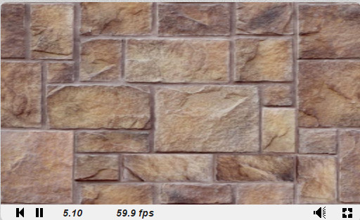
We only want to see the image, so the pixels will match on a 1: 1 scale:
void mainImage( out vec4 fragColor, in vec2 fragCoord ) { vec2 xy = fragCoord.xy / iResolution.xy;// vec4 texColor = texture(iChannel0,xy);// iChannel0 xy fragColor = texColor;// } So we got our first image!
Now, having learned how to correctly obtain data from a texture, we can do anything with it! We can stretch or scale them, experiment with colors.
Let's try to put a gradient on the image, similar to what we did before:
texColor.b = xy.x; Congratulations, you just wrote your first post-processing effect!
Task: Can you write a shader that makes an image in black and white?
Please note that although we have chosen a static image, everything that you see is performed in real time. To see this, replace the static image with the video: click on iChannel0 and select any video.
Add motion
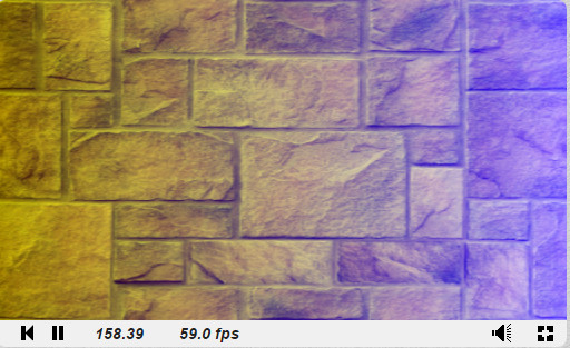
So far, all our effects have been static. We can do much more interesting things by using the input data provided by ShaderToy.
iGlobalTime is an ever-increasing variable. We can use it as a seed to create periodic effects. Let's try playing a little with the flowers: void mainImage( out vec4 fragColor, in vec2 fragCoord ) { vec2 xy = fragCoord.xy / iResolution.xy; // vec4 texColor = texture(iChannel0,xy); // iChannel0 xy texColor.r *= abs(sin(iGlobalTime)); texColor.g *= abs(cos(iGlobalTime)); texColor.b *= abs(sin(iGlobalTime) * cos(iGlobalTime)); fragColor = texColor; // } GLSL has built-in sine and cosine functions, as well as many other useful functions, such as getting the length of a vector or the distance between two vectors. Color values cannot be negative, so you need to get an absolute value using the
abs function.Task: Can you make a shader that changes the image from black and white to color and back?
Shader Debugging Note
When debugging code, you can execute it step by step or print values, but this is not possible when writing shaders. You can search for debugging tools for your platform, but in general, it is best to link the value to be checked to some graphical information that can be seen.
Summarize
These are just the basics of working with shaders, but by becoming familiar with them, you can achieve much more. See ShaderToy effects and see if you can understand or play them!
In this tutorial, I did not mention the Vertex Shaders (Vertex Shaders) . They are written in the same language, but they are executed for each vertex, not a pixel, and return with the color also the position. Vertex shaders typically project a 3D scene onto a screen (this feature is built into most graphics pipelines). Pixel shaders provide most of the complex effects seen on the screen, so I’m looking at them.
Another task: Can you write a shader that removes the green color from the video from ShaderToy and adds another video as the background of the first video?
ShaderToy , with which we worked earlier, is great for quick testing and experiments, but its capabilities are rather limited. For example, you can not control the data transmitted to the shader. If we have our own environment for running shaders, we can create all sorts of interesting effects and use them in our own projects! To run shaders in the browser, we will use the Three.js framework. WebGL is a Javascript API that allows rendering of shaders. Three.js is needed only to simplify the work.
If you are not interested in JavaScript or a web platform, do not worry, we will not go into the features of web rendering (but if you want to learn more about the framework, then learn this tutorial ). Setting up shaders in the browser is the fastest way to get started, but by becoming familiar with this process, you can easily set up and use shaders on any platform.
Customization
In this section, we will look at local shader configuration. You can repeat after me without having to download something thanks to this built-in widget CodePen :
You can create a fork and edit the project on CodePen.
Hello Three.js!
Three.js is a JavaScript framework that takes over most of the boilerplate code for WebGL needed to render shaders. The easiest way to start is to use the version laid out on the CDN .
You can download an HTML file that is a simple Threejs scene.
Save the file to disk and open it in the browser. You should see a black screen. It's not very interesting so far, so let's try to add a cube, just to check that everything works.
To create a cube, we need to define its geometry and material, and then add it to the scene. Add this code snippet to the
Add your code here field: var geometry = new THREE.BoxGeometry( 1, 1, 1 ); var material = new THREE.MeshBasicMaterial( { color: 0x00ff00} );// var cube = new THREE.Mesh( geometry, material ); // scene.add( cube ); cube.position.z = -3;// , We will not consider the cube in detail, because we are more interested in the shader. But if everything is done correctly, then you will see a green cube in the center of the screen:
While we are here, let's make it rotate. The
render function is executed every frame. You can access the cube rotation through cube.rotation.x (or .y , or .z ). Try increasing the value so the rendering function looks like this: function render() { cube.rotation.y += 0.02; requestAnimationFrame( render ); renderer.render( scene, camera ); } Task: Can you rotate the cube along a different axis? What about two axes at the same time?
So, everything is ready, it's time to add shaders!
Add shaders
At this stage we can start thinking about the implementation process of the shaders. Most likely, you will have a similar situation regardless of the platform: everything is set up, objects are drawn on the screen, so how do you get access to the video processor now?
Step 1: Download the GLSL Code
To create a scene, we use JavaScript. In other situations, C ++, Lua or any other language can be used. Regardless, shaders are written in a special shader language . The OpenGL shader language is called GLSL (Open GL S hading L anguage). Since we use WebGL based on OpenGL, we will write on GLSL.
How and where is GLSL code written? The main rule: the GLSL code is loaded as a
In JavaScript, this can be done by simply passing the code inside a variable, like this:
var shaderCode = " ;" This will work, but since there are no easy ways to create multi-line strings in JavaScript, this is not very convenient for us. Most programmers write shader code in text files and give them the extension
.glsl or .frag (short for fragment shader ), and then just load the file.This is possible, but in this tutorial we will write the shader code inside the new
<script> and load it into JavaScript from there so that all the code is in one file.Create a new
<script> in HTML that looks like this: <script id="fragShader" type="shader-code">; </script> We will assign him ID
fragShader so that you can access it later. The shader-code type is actually a non-existent, made-up type of script. (You can choose any other name for it). We do this so that the code is not executed and not displayed in HTML.Now let's insert a very simple shader that returns white.
<script id="fragShader" type="shader-code"> void main() { gl_FragColor = vec4(1.0,1.0,1.0,1.0); } </script> (The
vec4 components in this case correspond to the RGBA value, as explained at the beginning of the tutorial.)Now we need to download this code. We will do this in a simple JavaScript line that finds the HTML element and retrieves the inner text:
var shaderCode = document.getElementById("fragShader").innerHTML; It must be under the cube code.
Do not forget: only the code loaded as a string will be parsed as a valid GLSL code (that is,
void main() {...} . The rest is just a HTML boilerplate.)You can create a fork and edit the project on CodePen.
Step 2: Apply the Shader
The methods of using the shader may vary, they depend on the platform used and its interface with the video processor. There are never any difficulties with this, and a quick search can figure out how to create an object and apply shaders to it using Three.js .
We need to create a special material and pass it to the shader code. We will create a plane as a shader object (but we can also use a cube). Here is what you need to do:
// , var material = new THREE.ShaderMaterial({fragmentShader:shaderCode}) var geometry = new THREE.PlaneGeometry( 10, 10 ); var sprite = new THREE.Mesh( geometry,material ); scene.add( sprite ); sprite.position.z = -1;// , At this point, you should see a white screen:
You can create a fork and edit the project on CodePen.
If you replace the color in the shader code with another one and refresh the page, you will see a new color.
Task: Can you make one part of the screen red and the other blue? (If it doesn't work out, then in the next step I will give a hint!)
Step 3: Data Transfer
At this point, we can already do anything with the shader, but do not yet know what can be done. We only have the built-in ability to determine the position of the pixel
gl_FragCoord and, if you remember, this position is normalized. We at least need to know the size of the screen.To transfer data to the shader, we need to send what we call a uniform variable. To do this, we create an
uniforms object and add our variables to it. Here is the screen resolution transfer syntax: var uniforms = {}; uniforms.resolution = {type:'v2',value:new THREE.Vector2(window.innerWidth,window.innerHeight)}; Each uniform must have a
| Uniform String | Type GLSL | Javascript type |
|---|---|---|
'i', '1i' | int | Number |
'f', '1f' | float | Number |
'v2' | vec2 | THREE.Vector2 |
'v3' | vec3 | THREE.Vector3 |
'c' | vec3 | THREE.Color |
'v4' | vec4 | THREE.Vector4 |
'm3' | mat3 | THREE.Matrix3 |
'm4' | mat4 | THREE.Matrix4 |
't' | sampler2D | THREE.Texture |
't' | samplerCube | THREE.CubeTexture |
ShaderMaterial by adding a vector there: var material = new THREE.ShaderMaterial({uniforms:uniforms,fragmentShader:shaderCode}) We haven't finished yet! Now that the shader gets this variable, we need to do something with it. Let's create a gradient like we did before: normalizing the coordinate and using it to create a color value.
Change the shader code as follows:
uniform vec2 resolution;// uniform- void main() { // vec2 pos = gl_FragCoord.xy / resolution.xy; // ! gl_FragColor = vec4(1.0,pos.x,pos.y,1.0); } As a result, we get a beautiful gradient!
You can create a fork and edit the project on CodePen.
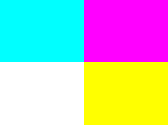
Task: Try to divide the screen into four equal parts of different colors. Like this:
Step 4: Update Data
It's good that we learned to send data to the shader, but what if we need to update them? For example, if you open the previous example in a new tab , and then resize the window, the gradient will not be updated, because it uses the old screen sizes.
To update the variables usually just re-send the uniform variable. However, in Three.js, it is enough just to update the
uniforms object in the render function; you do not need to re-send data to the shader.Here's what the rendering function looks like after making changes:
function render() { cube.rotation.y += 0.02; uniforms.resolution.value.x = window.innerWidth; uniforms.resolution.value.y = window.innerHeight; requestAnimationFrame( render ); renderer.render( scene, camera ); } If you open a new CodePen and resize the window, you will see how the colors change, despite the fact that the original size of the viewing window remains the same). The easiest way to notice this is by looking at the colors in the corners and making sure that they do not change.
Note: Sending data to a video processor is usually a costly task. Sending several variables in one frame is quite normal, but when hundreds of variables are transmitted per frame, the frame rate will drop significantly. It seems that this is unlikely, but if there are several hundred objects on the screen, and lighting with different properties is applied to all of them, then everything quickly goes out of control. Later we will learn about shader optimization.
Task: Try gradually changing colors.
Step 5: working with textures
Regardless of the method of loading and the format of textures on all platforms, they are transmitted to the shader as uniform variables.
A quick note about uploading files to JavaScript: you can easily upload images from an external URL (this is how we will do it). However, if you want to upload an image locally, you will encounter permissions problems, because JavaScript usually cannot and should not have access to files in the system. The easiest way to solve this is to start a local Python server , which is actually easier than it sounds.
In Three.js there is a small convenient function for loading an image as a texture:
THREE.ImageUtils.crossOrigin = '';// var tex = THREE.ImageUtils.loadTexture( "https://tutsplus.imtqy.com/Beginners-Guide-to-Shaders/Part2/SIPI_Jelly_Beans.jpg" ); The first line is given only once. You can paste any image URL into it.
Then we need to add a texture to the object
uniforms. uniforms.texture = {type:'t',value:tex}; And finally, we need to declare a uniform variable in the shader code, and then draw it in the same way as we did before - using the function
texture2D: uniform vec2 resolution; uniform sampler2D texture; void main() { vec2 pos = gl_FragCoord.xy / resolution.xy; gl_FragColor = texture2D(texture,pos); } A stretched candy image should appear on the screen:
(This is a standard test image in computer graphics, it is taken from the Signal and Image Processing Institute (SIPI) (therefore it shows the abbreviation IPI) University of Southern California. I think it suits us, because we are just studying graphic shaders!)
Task : Try gradually changing texture colors from full color to grayscale.
Additional step: apply shaders to other objects
There is nothing special about the plane we created. We could apply a shader to the cube. In fact, you can simply replace the line with the geometry of the plane:
var geometry = new THREE.PlaneGeometry( 10, 10 ); on:
var geometry = new THREE.BoxGeometry( 1, 1, 1 ); Voila, candy painted on a cube:
You can argue: “Wait, but this is not like the correct projection of the texture on the cube!” You are right: if you look at the shader, you can see that we are actually telling him “place all the pixels of this image on the screen”. The fact that they are on a cube simply means that all pixels outside of it are discarded.
If we wanted to apply the texture so that it looked physically painted on a cube, then our work would resemble the invention of the 3D engine again (which would be pretty stupid, considering that we already use the 3D engine and we can just ask itdraw the texture separately on each side). In this tutorial we use shaders for what would otherwise be impossible to achieve, so we will not go into such details. (If you want to learn more, Udacity has a great course on the basics of 3D graphics !)
Next steps
At this stage, we can already do everything that we did in ShaderToy, but now we are able to use any textures and any objects on any platform.
With all this freedom, we can do something like a lighting system, with realistic shadows and light sources. This we will do below. In addition, I will talk about shader optimization techniques.
Having mastered the basics of shaders, we will practically apply the power of the video processor to create realistic dynamic lighting.
From this point on, we will consider general concepts of graphic shaders without reference to a specific platform. (For convenience, all code examples will still use JavaScript / WebGL.)
First, find a suitable way for you to perform shaders. (JavaScript / WebGL is the easiest way, but I recommend you experiment with your favorite platform!)
Goals
By the end of this tutorial, you will not only begin to be well versed in lighting systems, but also create your own from scratch.
Here’s what the end result will look like (click the mouse to turn on the light):
Many game engines have ready-made lighting systems, but an understanding of how they are made and how to create your own gives you more opportunities to give the game a unique look. In addition, the shader effects do not have to be only “cosmetic”, they open the doors to stunning new game mechanics!
An excellent example of this is Chroma . The player can run on dynamic shadows created in real time:
Getting Started: Our Original Scene
We will miss a lot in the initial setup, because it is discussed in detail above. Let's start with a simple fragmentary shader rendering our texture:
There is nothing complicated going on here. The JavaScript code sets the scene and sends the shader the texture for rendering and screen sizes.
var uniforms = { tex : {type:'t',value:texture},// res : {type: 'v2',value:new THREE.Vector2(window.innerWidth,window.innerHeight)}// } In the GLSL code, we declare and use these uniform variables:
uniform sampler2D tex; uniform vec2 res; void main() { vec2 pixel = gl_FragCoord.xy / res.xy; vec4 color = texture2D(tex,pixel); gl_FragColor = color; } Before using pixel coordinates for texture drawing, we normalize them.
Just to make sure you understand everything, here’s a small warm-up task for you:
Task: Render the texture without changing its aspect ratio (Try it yourself, we will look at the solution below.)
It’s pretty obvious why the texture is stretched, but if it’s not clear then here’s a hint: look at the line where we normalize the coordinates:
vec2 pixel = gl_FragCoord.xy / res.xy; We divide
vec2by vec2, which is analogous to dividing each individual component. In other words, the above is equivalent to: vec2 pixel = vec2(0.0,0.0); pixel.x = gl_FragCoord.x / res.x; pixel.y = gl_FragCoord.y / res.y; We divide x and y into different numbers (by the width and height of the screen). Naturally, the image will be stretched.
What happens if we divide x and y
gl_FragCoordonly by x res? Or just on y?For the sake of simplicity, in the tutorial we will leave the normalized code the same, it would be nice to figure out what is happening here.
Step 1: Add Light Source
Before you create something interesting, we need a light source. The “light source” is simply a point transmitted to the shader. For this point we will create a new uniform:
var uniforms = { // light: {type:'v3', value:new THREE.Vector3()}, tex : {type:'t',value:texture},// res : {type: 'v2',value:new THREE.Vector2(window.innerWidth,window.innerHeight)}// } We have created a vector with three dimensions, because we want to use
x, and yas a position source on the screen, and z- as the radius .Let's assign JavaScript values to our light source:
uniforms.light.value.z = 0.2;// We will use the radius as a percentage of the screen size, so it
0.2will be 20% of the screen. (There is nothing special about this choice. We could set the size in pixels. This number doesn’t mean anything until we start doing something with it in the GLSL code.)To get the mouse position, you just need to add an event receiver (event listener ):
document.onmousemove = function(event){ // , uniforms.light.value.x = event.clientX; uniforms.light.value.y = event.clientY; } Let's now write the shader code to use this coordinate of the light source. Let's start with a simple task: let's make every pixel within the radius of the light source visible and the rest black .
On GLSL, this might look something like this:
uniform sampler2D tex; uniform vec2 res; uniform vec3 light;// uniform! void main() { vec2 pixel = gl_FragCoord.xy / res.xy; vec4 color = texture2D(tex,pixel); // float dist = distance(gl_FragCoord.xy,light.xy); if(light.z * res.x > dist){// , gl_FragColor = color; } else { gl_FragColor = vec4(0.0); } } Here we did the following:
- Announced uniform light source.
- We used the built-in distance function to calculate the distance between the light source and the current pixel.
- Check if this distance is longer (in pixels) 20% of the screen width; if so, then return the color of the pixel, otherwise return the black.
Oops!The light source follows the mouse in a strange way.
Task: Can you fix it? (Try to figure it out again before we solve this problem below.)
Correction of the movement of the light source
You may remember that the Y axis is inverted here. You can hurry to just enter:
light.y = res.y - light.y; This is mathematically true, but if you do this, the shader will not compile! The problem is that uniform variables cannot be changed . To understand why, you need to remember that this code is executed for each individual pixel in parallel . Imagine that all processor cores try to change a single variable at the same time. Bad situation!
We can correct the error by creating a new variable instead of uniform. Or even better - we can just take this step before transferring the data to the shader:
uniforms.light.value.y = window.innerHeight - event.clientY; Now we have successfully determined the apparent radius of our scene. However, it looks too sharp ...
Add gradient
Instead of simply trimming to black outside the radius, let's try to create a smooth gradient at the edges. You can do this with the help of the distance that we already calculate.
Instead of assigning all pixels within the radius of a texture color:
gl_FragColor = color; we can multiply it by the distance factor:
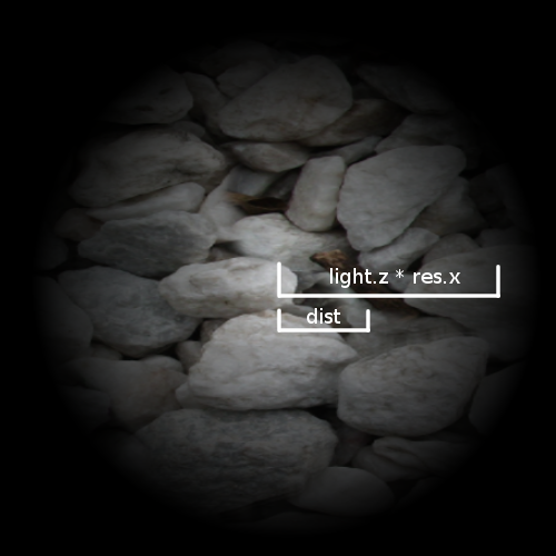
gl_FragColor = color * (1.0 - dist/(light.z * res.x)); This will work because
dist- this is the distance in pixels between the current pixel and the light source. (light.z * res.x)- is the length of the radius. So when we look at a pixel exactly under the light source, it’s distequal 0, that is, we multiply colorby 1and get the full color.This figure is
distcalculated for an arbitrary pixel. distchanges depending on which pixel we are in, and the value is light.z * res.xconstant.If we look at the pixel on the border of the circle, it
distis equal to the length of the radius, that is, as a result, we multiply colorby 0and get the black color.Step 2: Add Depth
Until we did anything special, we just added a gradient mask to our texture. Everything still looks flat . To understand how to fix it, let's see what the lighting system is doing now and compare it with what it should do.
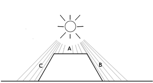
In the case presented above, we should expect that point A will be lit most of all, because the light source is directly above it, and B and C will be darker, because there are practically no rays on the sides.
However, this is what our lighting system sees now:
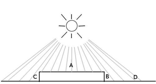
All points are processed the same way, because the only factor that the system takes into account is the distance on the xy plane.. You might think that we only need the height of each of these points, but this is not quite so. To understand why, consider this picture:
A is at the top of the figure, and B and C are on the sides. D is another point on earth. We see that A and D should be the brightest, with D being slightly darker because the light reaches it at an angle. On the other hand, B and C should be very dark, because they almost do not get the light, because they are directed from the light source.
The height is not as important as the direction in which the surface is rotated . It's calledsurface normal .
But how to pass this information to the shader? After all, we probably cannot transmit a huge array of thousands of numbers for each individual pixel? In fact, we do! Only we call it not an array , but a texture .
This is what makes normal map: it simply is an image in which the values
r,gandbeach pixel represents no color, and direction.The picture above shows a simple normal map. If you use the eyedropper tool, we see that the default direction (“flat”) is represented by color.
(0.5, 0.5, 1)(blue color occupying most of the image). This direction is pointing straight up. The values of x, y, and z are assigned to the values of r, g, and b.The sloping side on the right is turned to the right, so its x value is higher. The x value is also red, which is why the side looks a little reddish or pinkish. The same applies to all other parties.
The map looks funny because it is not intended for rendering, it simply encodes the values of the normals of these surfaces.
Let's load this simple dough normal map:
var normalURL = "https://raw.githubusercontent.com/tutsplus/Beginners-Guide-to-Shaders/master/Part3/normal_maps/normal_test.jpg" var normal = THREE.ImageUtils.loadTexture(normalURL); And add it as one of the uniform variables:
var uniforms = { norm: {type:'t', value:normal}, //.. } To check that we loaded it correctly, let's try rendering it instead of a texture, changing the code to GLSL (remember that at this stage we use just the background texture, not the normal map):
Step 3: Apply the Lighting Model
Now that we have the surface normal data, we need to implement a lighting model . In other words, you need to tell the surface how to take into account all the factors available to calculate the final brightness.
The simplest model to implement is the Phong model . Here's how it works: suppose we have a surface with normals data:
We simply calculate the angle between the light source and the surface normal:
The smaller the angle, the brighter the pixel.
This means that when a pixel is directly under the light source, where the angle difference is 0, it will be the brightest. The darkest pixels will point in the same direction as the light source (it will look like the back of an object).
Let's implement this model.
Since we are using a simple normal map for testing, let's fill the texture with a solid color to clearly understand whether everything works out.
Therefore, instead of:
vec4 color = texture2D(...); Let's make a solid white color (or any other color):
vec4 color = vec4(1.0); // This is a GLSL abbreviation for creation
vec4with all components equal 1.0.Here is the algorithm:
- Get the normal vector of the current pixel.
- Get the vector of the direction of light.
- Normalize the vectors.
- Calculate the angle between them.
- Multiply the final color by this factor.
1. Get the normal vector of the current pixel.
We need to know in which direction the surface “looks” so that we can calculate the amount of light falling on this pixel. This direction is stored in the normal map, so getting the normal vector is to get the color of the current pixel in the normal texture:
vec3 NormalVector = texture2D(norm,pixel).xyz; Since the alpha value doesn’t mean anything on the normal map, we only need the first three components.
2. Get the vector of the direction of light
Now we need to know in which direction the light points . You can imagine that the illumination surface is a flashlight aimed at the screen at the point of the mouse cursor. Therefore, you can calculate the vector of the direction of light simply by using the distance between the light source and the pixel:
vec3 LightVector = vec3(light.x - gl_FragCoord.x,light.y - gl_FragCoord.y,60.0); It must also have a Z coordinate (so that it is possible to calculate the angle relative to the three-dimensional vector of the surface normal). You can experiment with this value. You will notice that the smaller it is, the sharper is the contrast between bright and dark areas. One can imagine that this is the height of the flashlight above the stage: the farther it is, the more evenly the light spreads.
3. Normalize the vectors
Now we need to normalize:
NormalVector = normalize(NormalVector); LightVector = normalize(LightVector); In order for both vectors to have length
1.0, we will use the normalize built-in function . This is necessary because we want to calculate the angle using the dot product . If you do not really understand how it works, then you should study linear algebra a little. For our purposes, we only need to know that the scalar product returns the cosine of the angle between vectors of the same length .4. Calculate the angle between the vectors
Let's do this with the built-in dot function :
float diffuse = dot( NormalVector, LightVector ); I called the diffuse variable because this term is used in the Phong lighting model, because it determines the amount of light that reaches the surface of the scene.
5. Multiply the final color by this factor.
That's all.Now multiply the color by the value. I created a variable
distanceFactorto make our equation easier to read: float distanceFactor = (1.0 - dist/(light.z * res.x)); gl_FragColor = color * diffuse * distanceFactor; And we got a working lighting model! (Try increasing the radius of the light source so that the effect is more noticeable.)
Hmm, it seems something is wrong. It seems that the source is somehow inclined.
Let's look at our calculations again. We have a vector of light:
vec3 LightVector = vec3(light.x - gl_FragCoord.x,light.y - gl_FragCoord.y,60.0); Which, as we know, will give us
(0, 0, 60)when the light source is above the current pixel. After normalization, it will be equal (0, 0, 1).Do not forget that for maximum brightness we need a normal, directed strictly upwards, towards the light source. The default surface normal, upward, is
(0.5, 0.5, 1).Task: Do you understand what the solution is? Can you implement it?
The problem is that in the texture as the color values can not be stored negative values . It is impossible to denote a vector directed to the left as
(-0.5, 0, 0). Therefore, when creating normal maps, you need to add to everything0.5. (Or, to put it more generally, you need to shift the coordinate system). You need to understand this in order to know that before using the map you need to subtract from each pixel 0.5.Here’s what the demo looks like after subtracting the
0.5normal vector from the x and y coordinates:We need to make one more fix. Remember that the dot product returns the cosine of an angle. This means that the output is limited to the interval from -1 to 1. Color values cannot be negative, and since WebGL automatically discards negative values, in some cases the behavior will be strange. To solve this problem, you can use the built-in max function and turn it into:
float diffuse = dot( NormalVector, LightVector ); in it:
float diffuse = max(dot( NormalVector, LightVector ),0.0); And we have a working lighting model!
You can put a stone texture on the background, and take the real normal map in the repository of this tutorial on GitHub (namely here ):
We just need to change one line in JavaScript, with:
var normalURL = "https://raw.githubusercontent.com/tutsplus/Beginners-Guide-to-Shaders/master/Part3/normal_maps/normal_test.jpg" on:
var normalURL = "https://raw.githubusercontent.com/tutsplus/Beginners-Guide-to-Shaders/master/Part3/normal_maps/blocks_normal.JPG" And one line on GLSL:
vec4 color = vec4(1.0);// We no longer need a solid white color, we will load the real texture, like this:
vec4 color = texture2D(tex,pixel); And here is the final result:
Optimization Tips
The video processor performs its work very effectively, but it is very important to know what can slow it down. Here are some tips:
Branching
In shaders, it is usually desirable to avoid branching whenever possible . Although a large number of designs are
ifrarely a problem in any code for the CPU, in shaders for a video processor they can become a bottleneck.To understand why, it is worth remembering again that the GLSL code is executed for each pixel on the screen in parallel . A graphics card can perform many optimizations based on the fact that all pixels need to perform the same operations. However, if there is a heap in the code
if, then some optimizations will not be possible, because now different code is executed for different pixels. Will there be designsif slowing down or not depends on the implementation on the specific hardware and in the graphics card, but remember this if you want to speed up the shader.Deferred rendering
This is a very useful concept when working with lighting. Imagine that we need two sources of illumination, or three, or ten. We will have to calculate the angle between each surface normal and each point of the light source. As a result, the shader will run at snooty speed. Deferred rendering is a way to optimize such a process by splitting the work of the shader into several passes. Here is an article explaining in detail what this means. I will quote an important part for us:
— . .
For example, instead of transferring an array of points of light sources, you can draw them onto textures in the form of circles, the color of each pixel of which will represent the intensity of illumination. In this way, we can calculate the combined effect of all sources of lighting in the scene, and then simply transfer it to the final texture (or buffer, as it is sometimes called) to calculate the lighting.
The ability to divide work into several passes is a very useful technique when creating shaders. For example, it is used to accelerate the shader when calculating the blur effect, as well as in fluid / smoke shaders.
Next steps
Now that you have a working lighting shader, here’s something else you can experiment with:
- Try changing the height (value
z) of the light vector to observe its effect. - . ( , diffuse .)
- ambient ( ). ( , , . , , )
- WebGL . Babylon.js, Three.js, , GLSL. , - .
- GLSL Sandbox ShaderToy
Links
The stone texture and normal map for this tutorial are taken from OpenGameArt: http://opengameart.org/content/50-free-textures-4-normalmaps .
There are many programs to help create normal maps. If you are interested in learning more about creating your own normal maps, then this article can help .
Source: https://habr.com/ru/post/333002/
All Articles