Automata programming. Part 3. State and transition diagram. Continuation
State diagram! = Graph diagram.
As already mentioned, the state diagram is an alternative, more convenient form of recording software algorithms. Moreover, a state diagram is a natural form of recording a dynamic process, while an algorithmic graph-diagram is an artificial construction that already contains implementation features that are obvious and do not require that they be specified separately, or impair understanding in general. although technically correctly describe the sequence of required actions.
But the state diagram is not just another graphical notation of a graph diagram entry, it has some excellent features. Figure 1 (b, c) shows the state diagrams of the same automaton corresponding to the initial graph-scheme of the article fig. 1 (a).
')
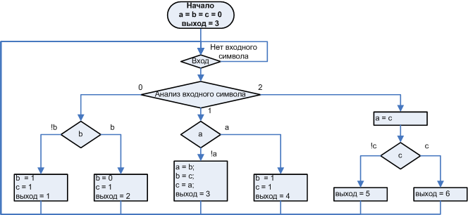
Figure 1 a). Original graph diagram
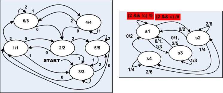
Figure 1 b), c). State diagrams of equivalent automata implementing the algorithm
(but).
Figure 1 (c) shows an example of incorrect recording of a state diagram and transitions. The incorrectness is that the transitions highlighted by the red rectangle are determined not only by the input events, but also additionally by the flag with, which for this state corresponds to the flag of the original graph diagram of fig. 1 (a), because of which it is no longer possible to monitor the state of the process, considering only the input symbols, you need to somehow take into account the logic of changing the flag c. The problem is not even in the flag itself, but in the fact that the logic of changing this flag is not tied to the state s1 alone. If events connected with the change of this flag would be associated only with s1, such a problem would not exist. The transitions highlighted in red depend on the way they hit s1 , which contradicts the definition of the automaton, according to which the reaction depends only on the input symbol and the current state. Let's call this the principle of automatism, to refer to it further in the text.
Graph diagram of a pronounced non-automatic implementation of the algorithm in fig. 1 (a) is not so easy to write in the form of a correct state diagram, since states are not clearly defined, and, accordingly, transitions between them are not determined. To chart the figure 1 (b) according to the algorithm of fig. 1 (a) it took to get an equivalent automaton . The method of obtaining equivalent automata for any graph-scheme will be the subject of consideration in one of the following articles. Now I will confine myself to stating that this can be done in principle , because any digital device, including any non-automatic program, is a digital automatic machine that has states in the mathematical sense , despite the fact that these states are not explicitly described. Such states are similar to quantum photons in quantum electrodynamics, they can be simplifiedly described: they are everywhere and nowhere specifically, but they exist and act.
In this example, due to randomness, each branch of the graph scheme corresponds to one state. In other words, each output symbol is obtained in only one state. However, if the logic of changing flags is different, it would turn out that one output symbol is obtained in several different states, or, to put it another way, the same branch of the graph scheme corresponds to several different states. This is an even more difficult case in terms of understanding.
Since we are talking about states, a completely natural question arises: "How many states will you have to deal with?" In the case of an automaton implementation, we set the number of states to some extent arbitrarily, based on needs.
In the case of a non-automatic approach, the number of potential states of an equivalent automaton is equal to:
$$ display $$ 2 ^ \ text {total_size_in all_variables_determining_behavior, bit. } $$ display $$
That is, adding even one variable defining behavior, such as bool, will double the number of “structural” ones, I will conditionally call them “circuit-specific possible” states. Many of these states are unattainable states. All unreachable states are excluded automatically, by a specially selected logic of actions on variables defining behavior and it is assumed that these actions, superimposing one on the other, will produce the desired result. From the point of view of psychology, let me remind you , this is a dynamic process as a sequence of multidirectional actions giving as a result the desired result. As mentioned earlier, a very complex form to understand. A good analogy of the difference between the automaton description (state diagram) and the algorithmic description (graph diagram) of a dynamic process can be the study instead of the graph of the function graph of its derivative.
In the case when there are few variables defining behavior, the complexity of the algorithmic description is not so noticeable, but with an increase in the number of such variables, the complexity of perception of the algorithm grows exponentially and depresses the psyche.
The term Variable Defining Behavior should be clarified. In the case of a manual implementation, this is in fact any variable that creates a branch of the algorithm. In the case of an automaton implementation, this is the variable Internal state . As a variable, the Internal state can be an enumeration type variable, where all states are listed (= just int), or even just a bool variable if there are only two states. Next, I will demonstrate different versions of software implementations of automata.
As already mentioned at the beginning of the article, the graph diagram is not only a form of recording an automaton, but also a form of recording a conventional algorithm. The fact that the conditional transition operation is depicted by the transition arrow, I think, is not surprising, but how to depict the cycle? Suppose our machine enumerates a rectangular table, that is, the total number of combinations of variables of the vertical and horizontal cycles is m * n . Does it mean that the resulting automaton will have as many states, or in other words how to write a cycle in automaton style?
Consider the cycle:
for(i = 5; i--; ){} From the point of view of the condition of this cycle, the value of the counter 5,4,3,2,1 is the same value. Yes, inside the body of the cycle i is a parameter, the program's behavior is different for different values of this parameter, but from the point of view of the mode of the for loop, the variable counter can take two values 0 and not 0. The variable i is a pseudoflag variable so to speak.
Returning to the table traversal machine, I note that this machine has two states and two pseudoflag variables:
- horizontal cycle counter , determines the state:
{0} - vertical cycle,
{1, ..., 5, ...} - Horizontal cycle, - The vertical loop counter determines the end-of-work condition.
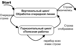
Figure 2. Recording nested loops using a state diagram.
The Out_text automaton from the example in the “Introduction” shown in fig. 3 is of interest from the point of view of events causing a change in the state of the automaton.

Figure 3. “Automatic display of text blocks”, state diagram.
The only event that can be considered as external is the end of the line, all other events of this automaton are purely internal, they are generated by the operation of the algorithm itself. However, this does not violate the principle of automatism, discussed above, because all events affecting the transition from a certain state are generated by the same state itself, that is, the behavior of the automaton does not depend on the way we got into this state.
An automatically implemented program can be represented as a graph diagram, and it will remain automatically realized. In fig. 4. shows an example of a graph diagram corresponding to the state diagram and transitions given at the beginning of the article
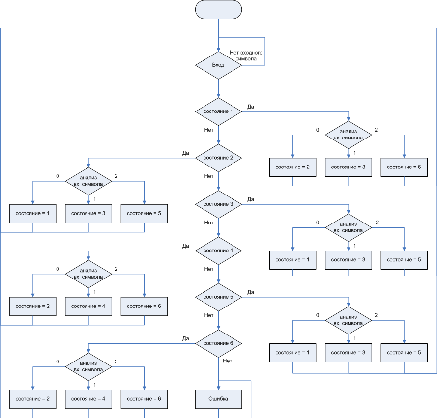
Figure 4. Graphic diagram corresponding to the automaton described by fig. 1 (b)
As you can see, when recording auto-implemented programs, the graph-diagram noticeably loses to the state diagram in terms of compactness.
Now consider what distinguishes automaton programming from automaton circuitry.
Artifacts of automatic circuitry.
To better understand what is being said, we introduce two categories of software automata - symbolic and functional. Symbolic automata are automata that accept a sequence of characters at the input and produce a sequence of characters at the output. This is a complete analog of classic abstract automata , automata which discrete mathematics itself actually considers. Symbolic automata are used to recognize codes, parse regular expressions, linguistic analysis, as well as to optimize functional automata, and algorithms in general. We will touch on ways to implement them further in today's article, and discuss in detail in one of the following articles.
These automata are opposed to functional software automata, (I will call them in the text programs) - a complete analog of the application and control programs of a computer or microcontroller. These are the same modules, subroutines that control the microcontroller periphery, or perform some useful work, or implement interactive work with the user, but they are designed and implemented automatically.
In automaton circuitry, the next stage after the development of an abstract automaton is structural synthesis, when abstract signals and states are encoded with “live” bits, coding methods are selected, and a logic circuit is built that works with already coded bits. Functional software machines is a software analogue of structural machines.
If we consider the functional automata solely from the standpoint of circuit design, and do not see anything more than structural automata in them, then such a narrow view rather hinders. This approach, which is a tracing paper from the automatic circuitry, provides a template for how the automatically designed module should be arranged.
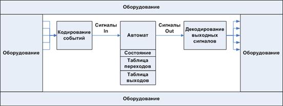
Figure 5. The generally accepted pattern of implementations of software automata
This leads to the fact that the design process becomes cumbersome, including not necessary in most cases, the formal steps prescribed by this template.
But not turning real-life processes into a set of formalized signals or using some “automaton” API gives an advantage to automaton programming. The advantage is given by the recording of the dynamic process in the categories of the state diagram; this makes programming more predictable. Proper partitioning of the automaton into the operational and control automata, and as part of this subdivision is the correct, reasonable choice of the operational automaton, this is what makes the solution effective, and in the next article it will be convincingly shown.
Mechanical copying of the behavior of the developer of circuit automatons, that's what I meant by the word artifacts that automaton programming gets rid of when leaving the automaton circuitry cradle, we are dealing with a program. The program is extremely comfortable and plastic material, and it is the plasticity of this material that made it so popular. By programming in the usual way, we are free from the routine of designing digital circuits. When we need to perform an action, we check the condition and execute it, and there is no need to write a special trigger function. What am I talking about? You can write this:
if(IO_latch->Data_1_received && IO_latch->Permission) { State = 5; } and so can
typedef bool paTrigger(); typedef void paAction(); struct tLink_Trigger_Action { paTrigger * Trigger; paAction * Action; int Next_state; }; bool Trigger_X(){return(IO_latch->Data_1_received && IO_latch->Permission);}; void Action_X(){State = 5;}; tLink_Trigger_Transition Table[States_max][ Triggers_max] = { /*State_0*/{}, /*State_1*/{ …,{ Trigger_X, Action_X }, … }, /*State_2*/{}, /*State_3*/{}, /*State_4*/{}}; uint Engine (uint Message) { if(State->Trigger()) { State->Action(); State = State->Next_state; } … } feel the difference?
The only thing that supporters of superformalism can argue is that with ordinary programming, there is less accounting, with the automatic-engineering method all bits are counted. To this, I will answer that if there is a problem with taking into account some parameter, it is worthwhile to create a submachine that will do the accounting, and to release the main machine from the routine. This is a advice on constructive decomposition.
The drama of the situation associated with programmatic programs lies in the fact that the automaton mental template, giving a convenient tool for modeling and analyzing dynamic processes, simultaneously dominates the developers with a heavy hand, depriving them of the simple pleasures of ordinary programming. This, in my opinion, is one of the most serious reasons why the automatic programming technology cannot rise higher than the exotic wonder.
As it is easy to guess, the natural way to overcome this contradictory situation is to take the best from both paradigms. In this case, the internal state becomes not so much an indication of how to handle the next incoming event, but it becomes a certain mode of operation. It is important. The state of rather should be considered as a subroutine in which the algorithm is located for some time. At the same time, it can process input signals, broadcast them on weekends, without going anywhere. It is implied that in one state the programmer performs the same type of work, everything that goes beyond the uniformity is transferred to another state. The transition from state to state is not made by any signal, but only by events that are significant for this algorithm. And we choose these events ourselves, based on the states we have chosen. And accordingly, each state-mode may contain nested programs.

Figure 6. Constructive pattern in which the state is the mode of operation .
But the programmer is not exclusively in function-mode until it has made the transition. He performs short iterations during which he controls the situation. At the same time, the application as a whole looks like:
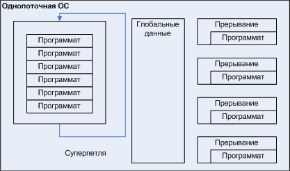
Figure 7. Programmers community.
That is, using programs, we come to the concept of corporate multitasking , only in contrast to the classical corporate multitasking algorithms, when a seemingly normal application itself appeals to the OS for some purpose and thus returns control of the system, the programs are initially designed as programs that take control only one step, execute it and transfer control back to the next iteration. The difference between corporate multitasking and programmers is formally conditional, but the automatic look at the programs implies their iterative nature, so there are no such problems that the programmer “forgets” to transfer control back.
Programs can work without problems and under control of multi-threaded OS, as shown in Fig. At the same time, of course, their corporate multitasking appears to be kind of not needed, but the automatic device of the module itself retains all the advantages discussed above related to automatic design.
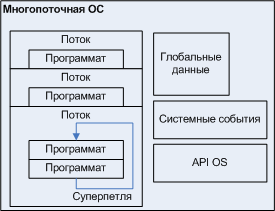
Figure 8. Programs in a multithreaded environment.
Since the programmer can perform one-time actions that occur when a transition is made, and can perform extended activities while in the same state — an operation mode — its state diagram acquires the features of both Mili’s automata and Moore’s automata. For example, an automatic parking meter, described by a state diagram.

Figure 9. The Parking Meter program, the description combines the features of Miles and Moore machines.
An example of a parking meter has not yet been considered, but looking at the state diagram one can easily understand what is being said. Please note that the description of this counter by the state diagram is much more informative than the description of the same automaton made with the help of the text.
From the point of view of the theory, I do not make an error, combining in one state diagram the features of Mili’s automata and Moore’s automata. When it will be necessary to perform mathematical operations on such an automaton, it can be considered as a Miles automaton. For abstract automata, with the same functional, the Mealy automaton can be obtained with a smaller number of states. There are mathematical methods for converting Mealy automata to Moore’s automata and vice versa.
Described sheds a little light on what are the programs, we turn to the methods of their implementation.
Ways to implement functional software machines.
Let's begin with the graph-scheme considered earlier, for convenience shown in fig. ten.
Figure 10. Graphic diagram to be implemented.
The most obvious solution that comes directly from the graph diagram to the forehead is to use the switch statement to determine the state of the construction of a multiple alternative of the C language. Upon receipt of the next input symbol, the program determines the current state, and for each state, the input symbol is analyzed, and for each input symbol, not only a transition to a certain state, but also an output symbol is specified.
#define mStep ((uword) (-2))// . uint Automaton (uint Input) { static uint State = 3; uint Out; {, , }; switch (State) { //////////////////////////////////////////// case 1: switch (Input) { /////////// case 0: { , }; State = 2; Out = 2; break; /////////// case 1: { , }; State = 3; Out = 3; break; /////////// case 2: { , }; State = 6; Out = 6; break; /////////// case mStep: break; } break; //////////////////////////////////////////// case 2: ... //////////////////////////////////////////// case 3: ... //////////////////////////////////////////// case 4: ... //////////////////////////////////////////// case 5: ... //////////////////////////////////////////// case 6: ... default: // Error }; return(Out); } Similar methods implemented automata in Switch-technology and in IAR visualState .
Since the concept of program states treats them as program modes in which it can function for some time without making transitions, but at the same time continuing its “minor activities”, there must be an input symbol that does not guarantee the programmer to translate into a new state ( unless he goes on himself, for internal reasons), but he activates it every iteration. Symbol pitch - mStep .
The second embodiment, fundamentally different: make the handler for each event, as shown in the listing
uint Message_i0_handler(uint &State) { uint Out; switch (State) { //////////////////////////////////////////// case 1: { , }; State = 2; Out = 2; break; //////////////////////////////////////////// case 2: { , }; State = 1; Out = 1; break; ... }; return(Out); } uint Message_i1_handler(uint &State) { ... } uint Message_i2_handler(uint &State) { ... } void Message_Step_handler(uint &State) { switch (State) { //////////////////////////////////////////// case 1: {, , }; break; //////////////////////////////////////////// case 2: {, , }; break; //////////////////////////////////////////// case 3: {, , }; break; }; return(mStep); } typedef uint (*paMessage_handler)(uint &State); paMessage_handler Reactions[3] = { Message_i0_handler_for_s1, Message_i1_handler_for_s1, Message_i2_handler_for_s1}; uint Automaton (uint Input) { Reactions [Input]; } The above options are basic options that reflect the basic ideas, but they are rather cumbersome and slow. However, they are modified without any problems in the direction of reducing the bulkiness (relative) and speeding up the work (real).
Modify the code shown in the listing of Option 2. We split each Message_ixx_handler event handler into a set of functions corresponding to each state.
uint Message_i0_handler_for_s1(uint &State) { { , }; State = 2; Out = 2; return(Out); } uint Message_i0_handler_for_s2(uint &State) { { , }; State = 1; Out = 1; return(Out); } ... uint Message_Step_handler_for_s1(uint &State) { {, , }; return(mStep); } In total it is meant that States * Messages functions are needed, although a part can be repeated, moreover there can be only a few of them.
If we now combine all the methods obtained into an array, the automaton will work from the root engine function, and the engine can be written as.
typedef uint (*paMessage_handler)(uint &State); paMessage_handler Reactions[6][3] = { { Message_i0_handler_for_s1, Message_i1_handler_for_s1, Message_i2_handler_for_s1}, ... { Message_i0_handler_for_s6, Message_i1_handler_for_s6, Message_i2_handler_for_s6}, }; paMessage_handler Reactions_for_Step [6] = { Message_mStep_handler_for_s1, ..., Message_mStep_handler_for_s6 }; uint Engine(uint Input = mStep) { uint State = 3; if(Input == mStep) return(Reactions_for_Step [State] (State)); else return(Reactions[State][Input] (State)); } With this option, the scheme of dispatching events in interrupt handlers and their processing from a single engine is well implemented.
A similar way underlies the implementation of the template boost.statechart.
The main disadvantage of the previous two options: they are artifacts of automatic circuitry, that is, programming in this way, it is impossible to preserve the “programming style” of programming, you have to use a tabular programming style that is excessively bloated.
Consider what gives the tabular programming style:
- "+" lists reactions to all events for each of the states (for unhandled events there are stubs), i.e. There is a full description.
- "-" But at the same time, everything is so unwieldy that it is realized that the total probability of a typo is large, or the stub is not left there. That is, we are not talking about improving reliability, despite the fact that automatic programming positions itself as a more reliable development method.
No wonder that IAR went the way of graphic programming of visualState automata, finding that the text-based auto-schematic style of programming is not for people.
Much more beneficial in terms of possibilities for modification is the option shown in the listing of Option 1, if it is expanded with the accepted concept of state-modes of operation.
Let the input handler for each state (external switch) be rendered into a separate function (function-mode).
uint State_1 (uint &State, uint Input) { {, , }; switch (Input) { /////////// case 0: { , }; State = 2; Out = 2; break; /////////// case 1: { , }; State = 3; Out = 3; break; /////////// case 2: { , }; State = 6; Out = 6; break; /////////// case mStep: // }; uint State_2 (uint &State, uint Input){...}; All newly functioned states-states are placed in an array, so that the state function can be specified by its index. Then the variable Internal state is an index, a value of type uint , and the engine takes the form
typedef uint (*paState)(uint &State, uint Input); paState States[6] = { { State_1, ..., State_6}, }; uint Engine(uint Input = mStep) { static uint State = 3; return(States [State] (State, Input)); } With the apparent similarity with option 3, this is more consistent with the concept of the program as a set of alternating modes. Each function-state is a function-mode, which itself polls all the peripherals it needs, or a synchronized frame of data from the periphery, and performs transitions based on this, and not only on the basis of the Input symbol.
The Input symbol may contain system messages of the same type for all programmers. This means, in particular, that the state-function itself can be written in the traditional, most familiar way.
This option shows a higher speed compared to option 1 , due to the fact that each value of the variable Internal state is uniquely associated with a function that processes this state, and the call of the state function is reduced to get a table cell that contains pointer to the desired function. At the same time, with the implementation of option 1 , the variable Internal state is repeatedly compared with the values that correspond to the state names.
Although this option is faster, the amount of routine is not reduced. The main disadvantage of this implementation is that you need to have both a state table and parallel accounting of states in the header and in the code file, and not copy / paste, so to speak, the problem of dual description. . . , , , -:
typedef uint (*paState)( void * argState, uint Input); uint State_1 (paState * State, uint Input) { {, , }; switch (Input) { /////////// case 0: { , }; State = (paState*) State_2; Out = 2; break; /////////// case 1: { , }; State = (paState*) State_3; Out = 3; break; /////////// case 2: { , }; State = (paState*) State_6; Out = 6; break; /////////// case mStep: // }; uint State_2 (paState *State, uint Input){...}; uint Engine(uint Input = mStep) { static paState *State = (paState*) State_3; return(State(State, Input)); } «» . , , switch
if(IO_latch->Data_1_received && IO_latch->Permission) { State = 5; } «» , - . , - . , ( — ), , : , , , . , , ( — ), , , « » .
«», tDisplay::Out_text, «». .

11.
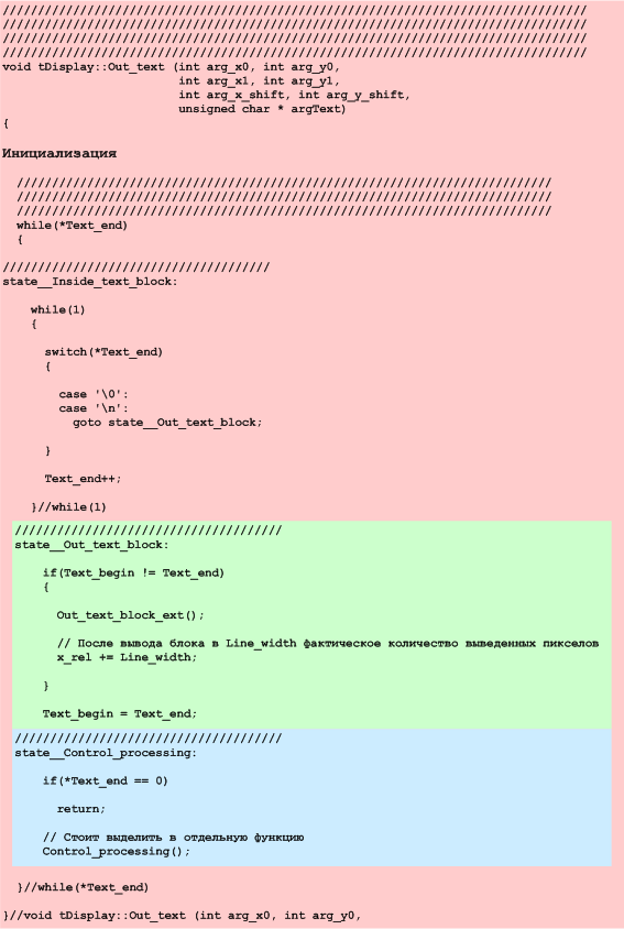
, . goto, — . — . .
goto __;
, . {}, (!). . , , goto. . , .
– , , Stall. , 7, , . , 6. , :
typedef uint (*paState)( void * argState, uint Input); #define mGoto(argState,argOut){\ State = (paState*)argState;\ return(argOut);\ } #define mStall_code ( (uword)(-1) ) #define mStall(){\ return(mStall_code);\ } // uint Engine(paState *State, uint Input = mStep) { return(State(State, Input)); } API - .
– , .
.
paState *Display_state; void tDisplay::Out_text (int arg_x0, int arg_y0, int arg_x1, int arg_y1, int arg_x_shift, int arg_y_shift, unsigned char * argText, TMemo * argDebug) { // Display_state = (paState*) state__Inside_text_block; // while(Engine (Display_state, 0) != mStall_code); return; }//void tDisplay::Out_text (int arg_x0, int arg_y0, //////////////////////////////////////////////////////////////////////////// //////////////////////////////////////////////////////////////////////////// //////////////////////////////////////////////////////////////////////////// uint state__Inside_text_block(paState * State, uint Input) { if(Input == mForce_Out_text_block) mGoto(state__Out_text_block, 0); while(1) { switch(*Text_end) { case '\0': case '\n': mGoto(state__Out_text_block, 0); } Text_end++; } }// uint state__Inside_text_block(paState * State, uint Input) //////////////////////////////////////////////////////////////////////////// //////////////////////////////////////////////////////////////////////////// //////////////////////////////////////////////////////////////////////////// uint state__Out_text_block(paState * State, uint Input) { if(Text != Text_end) { // . Out_text_block(); // Execute_script Line_width x_rel += Line_width; } // Text = Text_end; mGoto(state__Control_processing, 0); }// uint state__Out_text_block(paState * State, uint Input) //////////////////////////////////////////////////////////////////////////// ////////////////////////////////////////////////////////////////////////// //////////////////////////////////////////////////////////////////////////// uint state__Control_processing(paState * State, uint Input) { if(*Text_begin == 0) { mStall(); } // esc mGoto(state__Control_processing, 0); } , « ». , , , . . . Out_text , , .
API . 4, . 4.
uint State_1 (paState * State, uint Input) { {, , }; switch (Input) { /////////// case 0: { , }; mGoto(State_2,2); /////////// case 1: { , }; mGoto(State_3,3); /////////// case 2: { , }; mGoto(State_6,6); /////////// case mStep: // . return (0); }; API , .
. , , .
- static, . , - . . , , . .
.
. , , , , , . , a,b,c, 1 , , 0 .
bacab. . 12

12. bacab.
, , .
uint FSM[States_amount][Alphabet_size]; , . , 0 _ – 1. – . 0, « », , , , , 0, 1,2, … 0xff..ff. 1, 0.
, .
uint FSM[States_amount][Alphabet_size]; uint Engine(uint Input) { static uint State = 0; State = FSM[State][Index_for(Input)]; if(State == (uint)(-1)) { State = 0; return 1; } else return 0; } // while(!terminate) { if(Engine(Stream++)) goto Found; }; Stopped: // , Found: // } . . .
. – , .
Source: https://habr.com/ru/post/332664/
All Articles